Lavry AD11 User manual

LavryBlack Series
Model AD11 Stereo
Analog to Digital Converter
With
Microphone Preamplifier

Lavry Engineering, Inc.
P.O. Box 4602
Rolling Bay, WA 98061
http://lavryengineering.com
email: [email protected]
May 25, 2011
Rev 1.1

AD11 Table of Contents
Table of Contents
Subject Page
Quickstart Guide- Introduction: Line and Microphone Inputs 1
Quickstart Guide- Setting Example 2
Quickstart Guide- Diagram 1, AD11 Modes- Setting & Operation 3
Quickstart Guide- Diagram 1 Sections, Setting Controls 4
Quickstart Guide- Diagram 1 Section 2, Setting Status Display 4
Quickstart Guide- Diagram 1 Section 2, Level Display Meters 6
Quickstart Guide- Diagram 1 Section 3, GAIN Controls- Line/Mic 6
Quickstart Guide- USB Connection 6
Operation- Features and Connection 7
Operation- USB Operation 8
Operation- A. Front Panel Displays 9
Operation- B. Setting Mode- General Information 9
Operation- B. Setting Mode- Diagram 2 & Sample Frequency 10
Operation- B. Setting Mode- External Clock & Output Format 11
Operation- B. Setting Mode- +48V Phantom, Soft Saturation 12
Operation- B. Setting Mode- Meter Peak Hold 12
Operation- C. Setting & Operating Mode- GAIN Control section 13
Operation- D. Operating Mode- General Information 13
Specifications 15
Limited Warranty 16

AD11 Table of Contents

AD11 Quickstart Guide
1
Quickstart Guide- Introduction
Please Note: Because the AD11 uses the same XLR inputs for Line and Microphone level, it
is possible that Phantom power could be present on the input(s) if the user does not
exercise care in checking the phantom power settings and gain settings. In the vast majority
of cases, damage is very unlikely. Furthermore, because there are extensive safety features
to prevent this, it is unlikely to occur in normal usage; however:
- It is advisable to have phantom power enabled on the AD11 only when using condenser
microphones.
To familiarize yourself with the operation of the front panel controls of the AD11, it is
advisable to perform the Setting example procedure on page 2 before changing settings or
making any connections other than AC power. But first, here are some basics:
-When AC power is applied to the AD11, the unit initializes itself. First, a single LED “scans”
each row of the front panel meters, then both rows. The unit then enters a special version of
Setting Mode to display the settings and allow changes to the phantom settings for the left
and right channel’s +48V Phantom power.
-The unit then returns to Operating Mode.
For more details, please see the section titled “phantom (+48V Phantom Power for
Condenser Microphones)” in the Operation section of the manual on page 12.
All switches on the AD11 are spring-loaded three position toggles that automatically return
to the center (no function) position. They are: (forward-back), Exit-Set, and Up-Down.
The front panel LEVEL meters change modes; in Operating mode they serve as output level
meters and the numbers above the display indicate the peak level in dB’s below “0dB full
scale digital” (0dBFS). In Setting mode the legend below the display applies, and the bottom
row of LED’s (labeled “right”) indicate the status of most settings. However, for individual
channel settings the top row indicates the left channel setting, or for external clock
operation; “lock” to an external sync source. This also means that the cursor may move
vertically between the top and bottom row of LED’s to access the left and right channel
settings, in addition to moving left or right. For this reason, the direction of the cursor’s
movement will be referred to as “forward and back.” Please see Diagram 2 on page 10 for
more detailed information.
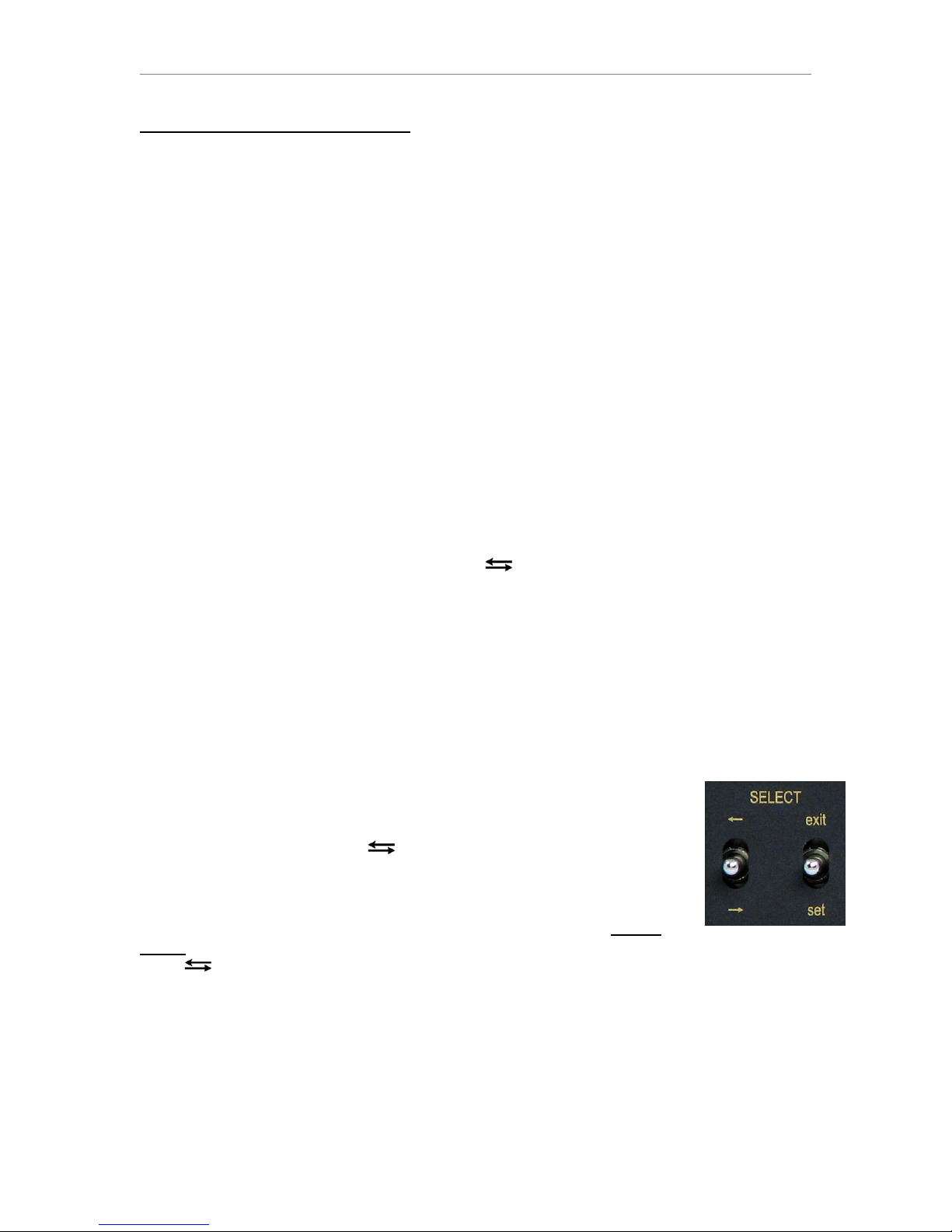
The two switches under the SELECT legend are used to change basic
settings.
- In Operating mode, click the (forward-back) switch down to enter
Setting mode. A flashing LED appears as a “cursor” in the “LEVEL”
display to indicate which setting can be changed.
-The AD11 is now in Setting mode and the display under the LEVEL
legend has changed modes from level meter to displaying the setting
status.
- The switch now moves the cursor forward or back as indicated by the arrows. Clicking
the switch down is “forward” and up is “back.”
- The right switch toggles the setting at the cursor position “On” or “Off” when the switch is
clicked down in the “set” direction. For single selections, repeated clicks in the set direction
will toggle the function “On” or “Off”with each click.
- Some settings require at least one selection to be “On” at all times (Sample Frequency &
Output Format). Once any of these settings is “On,”clicking setrepeatedly has no effect.
- Click the right switch up towards “exit” to exit the Setting mode.
Please see the Setting Example (next page).

AD11 Quickstart Guide
2
Quickstart Guide- Setting Example
This procedure assumes settings have not been changed from the factory defaults, which are:
44.1 kHz Sample Frequency (SF), spdif output format “on,”meter peak hold “on.”
1) Turn the AD11 power “on” and wait for the initialization to complete (meters stop moving
sequentially, setting status finishes being displayed, and display reverts to Meter mode).
2) Enter Setting mode by clicking the switch in the down direction.
The default Setting mode display looks like this (where symbolizes a rapidly flashing cursor):
3) A rapidly flashing cursor appears at the first position on the left (44.1) indicating it is “On.”
4) Click the switch down three times and a slowly flashing cursor appears at “96”(slow = Off).
The LED above 44.1 will illuminate constantly to indicate it is “On.”
5) Click the right (“exit-set”) switch down towards “set” and the cursor will begin flashing rapidly to
indicate that 96 (kHz) is “On.” The LED above “44.1” will go dark (44.1 is now “Off”).
6) Click the switch down three times to position the flashing cursor above the aes legend. The
LED above 96 will stop flashing and stay illuminated.
7) Click the right switch down towards “set” and the cursor will change from flashing slowly to flashing
rapidly to indicate that aes (digital output format) is now selected. Because the aes and spdif
settings are also interlocked, the spdif LED will also go dark.
8) Click the switch down three times until the cursor appears in the left (upper) row of LED’s
above the phantom legend. Please note how the cursor goes to the right (lower) row of LED’s
before moving to the left row. This is because there are individual settings for left and right
channel.
9) Click the right switch down towards set; the cursor will change from flashing slowly to flashing
rapidly to indicate the phantom (+48V power) is now “enabled” for the left channel only.
10) Click the switch down three times until the cursor appears above the hold legend. Click the
right switch towards set and the cursor will change from flashing rapidly to flashing slowly to
indicate that the peak hold function has been turned “off.”
The display should look like this (where symbolizes a slowly flashing cursor):
96kHz SF, AES output format, phantom power enabled left channel, meter peak hold “off”
Hint: To double-check if a setting is correct, use the switch to move the cursor away from the
setting you just changed to see if its LED indicator is “On” or “Off”(instead of flashing).
11.) Click the right switch up towards “exit” to exit the Setting mode. The settings have been stored in
memory and the AD11 is now in Operating mode.
12.) Now that you are familiar with the Setting mode, you can re-enter setting mode and configure the
AD11 for the settings you normally use. It is advisable to disable phantom power unless you plan
to use a condenser microphone with the AD11 the next time power is applied. The default
settings can be used safely for initial operation.
13.) Please see the CONNECTIONS section of the manual before using the AD11.

AD11 Quickstart Guide
3
Quickstart Guide- Settings and Operation
The AD11 front panel has three sections: (Diagram 1)
When AC power is applied to the AD11, the unit initializes itself. First, a single LED “scans”
each row of the front panel meters, then both rows. The unit then enters a special version of
Setting Mode to display the settings and allow changes to the phantom settings for the left
and right channel’s +48V Phantom power. The unit then returns to Operating Mode. For
more details, please see the section titled “phantom (+48V Phantom Power for Condenser
Microphones)” in the Operation section of the manual on page 12.
- Please use caution when changing settings. Although the AD11 changes its digital
outputs “gracefully;” it is not possible to predict how a device the AD11 is feeding
will react. For this reason; it is advisable to lower your monitor speaker volume to
avoid possible speaker damage prior to changing any settings.
AD11 MODES
The AD11 has two modes- the Operating Mode and the Setting Mode.
- In Operating mode, the front panel displays the level of the digital output signal in the
meters below the LEVEL legend (as shown on Page 7). The legend above the window
applies in this mode (-42 through 0) to indicate dB level below 0dB full scale digital level
(0dBFS). The GAIN display indicates the setting of the left or right channel when the
up/down switch for that channel is actuated, and for approximately 10 seconds afterwards.
The GAIN display then reverts to displaying “LE.” A quick “click” of either channel’s up/down
switch will display the stored setting for that channel without changing it. Please see
“Diagram 1, Section 3 Gain Controls”(page 6) for details on the behavior of the GAIN
control; including when switching between Line and Mic range. The GAIN control is always
active in both Operating and Setting modes; but is most likely to be used in Operating mode.
- In Setting mode (as illustrated above in Diagram 1), status of the settings is displayed as
well as the position of the cursor in the LEVEL display section. The legend below the
window applies in this mode (44.1, 48, wc, sat, etc). The position of the cursor is denoted by
the flashing LED. For settings at the cursor position, a rapidly flashing cursor means the
setting is “On” and a slowly flashing cursor means the setting is “Off.” At all other positions, if
the LED is illuminated the setting is “On,” and if the LED is dark the setting is “Off.”
- If the function has a left and right setting, the left setting is on the upper row (“left channel
meter” in Operating mode) and the right channel setting is on the lower row (“right channel
meter” in Operating mode).
- When an external clock setting is selected, the LED in the upper row directly above the
type of sync will indicate “lock” to the external signal. The two types of sync are “wc” for
Word Clock or “dig-a” for AES or SPDIF sync. If the AD11 is not “locked,” or there is no
signal present on the sync input, the LED in the upper row above wc or dig-a remains dark.

AD11 Quickstart Guide
4
- Exiting Setting Mode causes the settings to be stored in non-volatile memory. This means
the AD11 will retain the settings even if the AC power is turned “off.” Any time the GAIN
display reverts to the “LE” symbol, the Gain settings are also stored.
Diagram 1, Section 1- Setting Controls
The two switches under the SELECT legend on the left side of panel control the Setting
mode of the AD11. The first switch labeled with the symbols has two functions:
- Clicking the switch down in the Operating mode causes the AD11 to enter Setting mode. A
flashing cursor and indicators for settings that are “on” will appear in the LEVEL display
window. The legend under the window apply in this mode (44.1, 48, wc, etc.).
- While in Setting mode, clicking the switch down moves the cursor forward to the next
position and clicking the switch up moves the cursor one step back to the previous position.
- For convenience, the position of the cursor is retained when exiting Setting mode. The
cursor will appear at the same position when Setting mode is re-entered to allow easy
access to the same setting. The exception is when the unit is first powered; in this case the
cursor always appears at 44.1 (the first position).
The second switch is labeled “exit” and “set”and when in Setting mode:
- Clicking the switch down (set) toggles the function On or Off. For single selections, the
function is toggled On or Off every time the switch is “clicked” in the set direction.
- In the case of selecting a sample frequency (SF); the SF at the cursor position is enabled
and all other SF’s are disabled the first time the switch is clicked in the set direction.
Subsequent set “clicks” have no further effect.
- In the case of selecting digital output format (aes or spdif), the setting at the cursor
position is enabled and the other one is disabled the first time the switch is clicked in the set
direction. Subsequent set “clicks” have no further effect.
- Clicking the switch up (exit) immediately exits the Setting mode.
After exiting the Setting mode, clicking the switch in either direction has no effect on
settings. If the meter Peak Hold function is enabled, a set click clears the held value.
Diagram 1, Section 2- Settings Status Display (only in Setting mode)
In Setting mode, the LED’s above each label indicate the status of each setting. The cursor
position affects the way an LED indicates the status.
- At the cursor position, a rapidly flashing LED indicates “on” and a slowly flashing cursor
indicates “off.”
- At all other positions, a steadily illuminated LED indicates “on,” and an LED that is not
illuminated indicates “off.”
- Please note that in the following Setting mode function descriptions, the distinction
between whether or not the LED is at the cursor position may be omitted for clarity.
- Sample Frequency selection. This consists of the 44.1, 48, 88.2, and 96 labels and the
LED’s above them. Only one sample frequency (SF) can be selected at any time.
- If the cursor is positioned at the selected SF, the LED flashes rapidly.
- If the cursor is positioned at an SF that is not selected, the LED flashes slowly.
- When the cursor is at a different position than the selected SF, the LED for the selected SF
is constantly illuminated while the LED for the cursor flashes slowly. Clicking the set switch
will enable the SF at the cursor position and disable the previously selected SF (the
constantly illuminated LED will go dark and the cursor will flash rapidly).
- Once an SF is selected and the cursor is still at that position, subsequent set clicks have
no effect (one SF setting will always be selected).

AD11 Quickstart Guide
5
- External Word Clock. This setting enables synchronization to an external Word Clock
signal at the Sample Frequency set in the SF section (above). The LED in the “left channel”
row” above wc indicates “Lock” to an external Word Clock signal. Please see Diagram 2 on
page 10 for more details- the wc Lock indicator is labeled “a” in Diagram 2.
- If the external wc function is “On” as indicated by the LED, the AD11 will lock to TTL level
sample-period Word Clock signals applied to the “clock in” BNC connector on the rear
panel. The Sample Frequency (SF) of the Word Clock signal must match the AD11’s SF.
- If the wc setting is “off,” the AD11 will not lock to external Word Clock inputs.
Like other functions in the Setting mode, if the cursor is positioned at the wc LED, it will
flash rapidly to indicate that the function is “on.” Clicking the set switch once will disable
external WC functions and this will be indicated by a slowly flashing LED. When the cursor is
at another position, the LED is “off” (not illuminated) when the WC function is “off,” and the
LED is “on” when the function is “on.”
- The wc and dig-a functions are interlocked so that only one can be enabled at any time.
However; they both can be “Off.”
- External AES/SPDIF Sync- The setting designated “dig-a”(digital audio) enables
synchronization to an external AES or SPDIF signal at the Sample Frequency set in the
AD11’s SF section (above). The LED in the left row above dig-a indicates “Lock” to the
external AES or SPDIF signal. This LED is labeled “b” in Diagram 2.
- If the external dig-a function is “On” as indicated by the LED, the AD11 will lock to either
an AES or SPDIF digital audio signal applied to the “clock in” BNC connector on the rear
panel.
- If the dig-a setting is “off,” the AD11 will not lock to external AES or SPDIF sync inputs.
- Use of a digital audio signal that contains “muted audio” (“digital black”) is recommended
as an external sync signal to minimize jitter effects. AES sync is preferable to SPDIF sync.
- aes and spdif. These settings determine the configuration of the digital output format. The
digital audio signal from both the XLR and RCA digital outputs will contain the same digital
code format, as determined by these settings. The output format must be either AES or
“SPDIF” (IEC 60958 type II), and the setting function is interlocked so that one of the two
settings is always active.
- phantom. This function is controlled separately for each channel, and automatically
becomes inactive for gain settings of 12dB or less. The +48V phantom power function is
enabled on the left channel input when the left channel LED is on, and is enabled for the
right channel input when the right channel LED is on (for gain settings from 20 to 65dB).
Please Note: Phantom power turn “on” is ramped to minimize the possibility of
damage to ribbon microphones. However, caution is still advised when using ribbon
microphones with the AD11, especially vintage ribbon microphones.
-sat. The AD11 features Lavry’s exclusive digital tape saturation emulation (“Soft
Saturation”) which can be enabled and disable separately for each channel. This function
provides peak level control without attack and release times, and automatically adds 3 dB’s
of gain to the digital output for signals below “-3dBFS.”
- When this function is enabled, signals below “-3” on the AD11’s meters are completely un-
altered (linear), and signal peaks above this level are progressively “rounded-off” in a
manner similar to analog tape saturation.
- Internally, signals that would normally reach “0dBFS” are reduced to -3dBFS, thus allowing
the sat function to raise the average signal level by 3 dB’s (for signals below the “saturation
threshold”). This also causes the peak digital output level to be restored to “0dBFS.” As a
result, it is still possible to “clip” the output signal if this input signal level is exceeded.

AD11 Quickstart Guide
6
In other words, the same analog input level will result in digital “clipping;” but the average
output level of typical music program will be 3dB’s louder.
- The left row LED indicates the status of the left channel sat setting, and the right row LED
indicates the status of the right channel sat setting.
- hold. This setting enables and disables the LEVEL meters’ peak hold function. In
Operating mode when hold is enabled, a single LED representing the highest peak level
stays illuminated on each channel until the exit/set switch is clicked in the set direction.
Diagram 1, Section 2- LEVEL DISPLAY METERS (Operating mode)
This section displays the digital level of the output signal of the AD11 in decibels referenced
to “Zero dB Full Scale”digital level (all bits “On”) which will be referred to as “0dBFS.” The
numbers above the display apply in Operating mode (-42, -36, …, 0) and represent the peak
signal level in dB’s below 0dBFS. Just to the left of the display, the legends left and right
indicate which input channel the meters display.
Diagram 1, Section 3- GAIN CONTROLS (Setting and Operating Mode)
This section contains the GAIN display and separate “up/down” switches for the left and
right channels.
- The up/down switches always control the gain in both Operating and Setting modes.
- The display can show the gain setting for either channel. The gain for each channel is
displayed when the up/down switch for that channel is activated, and for approximately ten
seconds afterwards. The GAIN display then reverts to “LE” to indicate that the GAIN settings
have been stored in non-volatile memory.
- Because the same GAIN controls are used for both Line level and Microphone inputs,
there are two different GAIN ranges. The range from 0 to 12dB of gain is for line level inputs,
and the range from 20 to 65dB is for microphones or other balanced low-level, low
impedance sources. The GAIN display will STOP changing and flash before the GAIN is
changed from 12db to 20dB, or from 20dB to12dB to indicate the change in operating
modes. It is necessary to release the GAIN toggle switch, wait for the display to stop
flashing, and then press it again to transition from one range to the other. Please see the
Operating section of the manual for more details. For clarity, the condition “within the Line or
Mic range” may be omitted (below).
- If “LE” appears in the GAIN display and the up/down switch is “clicked” once, the GAIN
setting for that channel is displayed without change to the setting. If the display has not
reverted to “LE” and the same switch is clicked again, or held (either up or down), the gain
setting will change.
- If the numerical GAIN setting is displayed and the switch for the other channel is clicked
once, the setting for the other channel is displayed without change.
- If the numerical Gain setting is displayed, and the switch for that channel is clicked once,
the gain changes by one dB. There is an “acceleration” function, so when the switch is held,
the gain setting changes slowly at first, and then more rapidly the longer the switch is held.
- The GAIN display shows “LE” at other times to indicate that the settings have been stored
in memory. Again, to simply check the Gain setting for each channel, click that channel’s
up/down switch once. The setting will be displayed without change from the stored value if
“LE” is displayed, or the other channel’s numerical gain setting was being displayed.
USB Connection- Please see “USB Operation” in the Operation section of the manual (on
page 8) for more details on computer audio settings. The AD11 appears as a Core Audio
input device in Apple OSX and a WDM input device in Windows OS. ASIO4ALL can be
used with PC’s with ASIO compliant recording software.

AD11 Operation
7
MODEL AD11
The LavryBlack AD11 features:
-Built in Microphone preamps with phantom power
-Accepts +4 or -10 line level inputs balanced or unbalanced (MicPre’s are relay bypassed)
-Front panel adjustable gain for each channel
-0 to 12 dB of gain for line level inputs in precise 1 dB steps
-20 to 65 dB of gain for low impedance balanced microphone inputs in 1 dB steps
-Recording at 44.1, 48, 88.2 or 96 kHz with 24 bit word length
-Super-stable internal clock
-External clocking via Word Clock or AES/SPDIF sync
-BNC Word Clock output for synchronizing other gear to the AD11
-Digital output format selectable between AES/EBU and SPDIF (IEC 60958 type II)
-Peak hold selectable on large wide range LED meters
-Soft Saturation for “hotter” level and peak level control without time constants
-Optional Rack Mount Kit (can be used to mount any combination of two LavryBlack units)
CONNECTIONS
Connect analog audio INPUTS from your source using any of the following:
- Professional line level “+4dBu” balanced or unbalanced sources to the XLR inputs
- Consumer line level “-10dBV” balanced (TRS) or unbalanced (TS) to ¼” inputs
- Low impedance balanced sources (typically microphones) to the XLR inputs for gains >12dBs.
Phantom power is selectable individually for each channel via the front panel.
Stereo digital audio outputs are in the form of XLR, RCA, and USB:
- The XLR and RCA digital audio output connectors can transmit either AES/EBU professional format
or IEC 60958 type II consumer format (“SPDIF”).
- If more than one digital audio output is needed, a simple XLR to RCA adapter can be used to feed
most coaxial SPDIF inputs from the XLR output, and similarly, a simple RCA to XLR adapter or
adapter cable can be used to feed most AES inputs from the RCA output.
- Connect an external TTL level Word Clock, AES sync, or SPDIF sync to the clock in BNC
connector for external clock operation. The input has 75 Ohm termination.
- Connect the BNC clock out to another device’s Word Clock input to synchronize it to the AD11
operating on Internal Clock. The receiving device must have 75 Ohm termination.

AD11 Operation
8
- The USB output can be used to connect to a Windows®PC or Apple®computer that supports USB
2.0. There are no drivers to install; but ASIO4ALL can be installed on Windows PC’s for use with
ASIO compliant software. Please see the next section for details on USB operation.
Once the inputs and outputs have been connected:
- Connect the AC power cord to the AD11’s back panel power entry receptacle.
- Connect the AD11 and other devices to an AC power source. The AD11 will automatically adjust to
AC power inputs in the range of 90-264 VAC- no need to change settings!
USB Operation
The AD11 has a USB output compatible with the USB 2.0 standard. It is not necessary to install any
drivers with Windows®OS or Apple®OS for basic operation.
For ASIO operation, ASIO4ALL is available as a free download and can be used to make the AD11
operate as an ASIO input device. Please note that the operation varies when using ASIO4ALL and
some of the Windows settings may be bypassed. For example: the recording software’s sample rate
settings over-ride the SOUND control panel settings, the level control does not function, and there is
no level indicated on the “meter” next to the “Microphone 2-Lavry ADC” in the Recording tab when the
ASIO application (recording software) is opened. Also, if the SOUND control panel is open at the
same time as the recording application, the input signal may be unavailable to the recording software.
With the OS started normally and the AD11 power “On,” connect the USB cable from the AD11 to a
USB port on the computer. Although the AD11 should now be capable of inputting digital audio to an
application, it is a good idea to change a few settings for “bit-accurate” operation.
Windows ® XP:
Open the SOUND control panel, and in the Sound and Audio Device Properties dialog, select the
Audio tab. In the SOUND RECORDING section, select the Lavry ADC as the Default Device from the
drop-down list.
Due to the nature of the USB interface, for highest quality it is advised that you set the AD11 to the
same sample frequency as the recording software.
Windows ® Vista/Seven-
Due to the nature of the USB interface, for highest quality it is advised that you set the AD11 and the
setting in the SOUND/Recording Device/”Microphone Properties”/Advanced tab Settings to the same
sample frequency as the recording software.
In the SOUND control panel Recording tab, the AD11 will appear as a “Microphone.” Either click on
the “Lavry ADC microphone” and then on the Properties button in the lower right, or just double-click
on the “Lavry ADC microphone” to open the Microphone Properties dialog. Under the Microphone
Properties Advanced tab, choose the desired sample frequency for the “Default Format.” The level
control will need to be set to “3” (percent) or -0.4dB to avoid clipping. The settings for Exclusive Mode
may also affect operation with audio software- check them if you have problems.
Apple®OSX-
Due to the nature of the USB interface, for highest quality it is advised that you set the AD11 and the
setting in the Audio MIDI Setup/Audio Devices/Lavry ADC- Input Settings to the same sample
frequency as the recording software. Please be certain that your audio software is open first, as this
can affect whether or not the setting dialog appears in the right pane of the Audio Devices dialog.
- Select “Utilities”from the Finder “GO” menu. For easier access in the future, you may want to drag
the “Audio MIDI Setup” to the Dock. Open the “Audio MIDI Setup” dialog. Choose AUDIO DEVICES.
If the Lavry AD11 is connected, it should appear in the left pane of the Audio Devices dialog as “Lavry
ADC, 2 In/0 Out.” Click on it to select it. If a small black microphone symbol is not preset on the right
side of the Lavry ADC section, at the bottom of the left pane, click on the down arrow next to the gear

AD11 Operation
9
symbol, and select “Use this device for sound input.” In the right pane, under “Input,” select the
desired sample frequency from the dropdown list under FORMAT.
- The Lavry ADC is now available for use in an “Aggregate device.” Click on the Aggregate device if it
already exists, and in the right pane confirm that the current “Lavry ADC” has a check-box next to it. If
the AD11 was unplugged, or the AC power was turned “off;” the USB connection will be re-set. This
can result in two “Lavry ADC’s” appearing in the list in the right pane- the original one (grey- now
disabled) and the “new” one. You must un-check the old one and check the box next to the new one
for the AD11 to function as the input in the aggregate device! The “old” Lavry ADC will disappear
when the box is un-checked.
- You can add the Built-In Output to the aggregate device for playback. If you are using an external
DA converter such as the LavryBlack DA11, be certain to set the Output settings of the Built-In
(digital) Output to the proper sample frequency and “24 bit” for highest quality.
For more information on USB operation, including application–specific recommendations; please
check under the SUPPORT tab of the Lavry Engineering website: www.lavryengineering.com
OPERATION:
When AC power is applied, the AD11 initializes itself. First, a single LED “scans” each row of the front
panel meters, then both rows. The unit then enters a special version of Setting Mode to display the
settings and allow changes to the phantom settings for the left and right channel’s +48V Phantom
power. The unit then returns to Operating Mode. For more details, please see “phantom (+48V
Phantom Power for Condenser Microphones)”in the Operation section of the manual on page 12.
A. FRONT PANEL DISPLAYS
The AD11 has two modes- Operating Mode and Setting Mode.
In the center of the front panel, the LEVEL display has two modes:
1.) In OPERATING mode, two rows of LED’s serve as peak digital level meters for the left and right
channels. The legend above the display (-42, -36, -30,…, 0) indicate the level in decibels relative to
full scale digital or “0dBFS;” which corresponds to “digital clipping” level or “all bits = 1.” The top LED
“0” thus acts as a “clipping” indicator. The meters also have a Peak Hold function, which can be reset
and enabled or disabled via the front panel SELECT switches.
2.) In SETTING mode the status of all of the programmable settings are displayed. The legend for the
indicators in Setting mode is below the display (44.1, 48, …, sat, hold).
- Most of the settings use only the lower row of LED’s (the meter “right” channel); but some also use
the upper row of LED’s (meter “left” channel). These are: wc, dig-a, phantom, & sat.
wc and dig-a are external clock modes. The LED immediately above each of these labels (in
the lower “right”row) is the setting status display. The LED’s in the top row (“left”) are the
LOCK indicators for each type of sync (wc or dig-a). Only one LOCK indicator can be
illuminated at any time, and will only illuminate when the AD11 is successfully locked to the
external sync. Please see Section B “wc & dig-a” on page 11 for more details.
phantom and sat functions are selectable on each channels; for these settings the upper
LED (“left”) indicates the status of the left channel setting and the lower LED (“right”)
indicates the right channel setting.
On the right side of the front panel, the GAIN display has two modes: left channel and right channel. -
- This display does not change between Setting and Operating mode.
- The display always shows the Gain setting of the channel that was last adjusted.
- The display shows the setting for approximately ten seconds after the adjustment, and then reverts
to “LE” to indicate the gain setting has been stored in non-volatile memory.
- If the display shows “LE” and either channel’s up/down switch is clicked once, the gain setting for
that channel is displayed without change from the stored value.
- If the GAIN display shows one channel’s numerical Gain setting and the other channel’s up/down
switch is clicked once, the gain setting for the new channel is displayed without change from the
stored value.

AD11 Operation
10
For more details on the GAIN controls, see Operation manual section “C. GAIN SETTING.”
B. SETTING MODE
- Please use caution when changing settings- phantom power settings as well as “digital”
settings. This applies to changes between Line and MicPre range; but not to changes of Gain
within Line or Mic range. Gain changes within a range can be made at any time. Although the
AD11 changes its digital outputs “gracefully;” it is not possible to predict how a device the
AD11 is feeding will react. For these reasons; it is advisable to lower your monitor speaker
volume to avoid possible speaker damage prior to changing the relevant settings.
Diagram 2 illustrates the AD11 front panel display in SETTING mode. The numbers indicate the
sequence in which the cursor moves with each click in the downward direction of the switch.
Please note that the phantom and sat functions have individual left and right channel settings.
SETTING MODE STATUS DISPLAY Diagram 2
To enter the Setting mode, click the switch under the SELECT legend once either up or down.
The LEVEL display will change from meter mode to indicate the status of the programmable settings.
To exit the Setting mode, click the right SELECT switch up towards “exit.” The LEVEL display will
revert to the Operating mode; indicating the peak digital output level and that the programmable
settings are stored in non-volatile memory. This means the settings will be retained if the power is
turned “Off” and restored when the power is turned back “On.”
- The first time Setting mode is entered after power is applied, the left-most LED (44.1) will begin
flashing. If other functions are enabled, the LED’s above their legend will be illuminated.
- At all other times, when Setting mode is exited the position of the cursor is retained; so upon re-
entering Setting mode it will appear at the same position.
The LED at the cursor position indicates the status of the function differently than other positions-
- At positions other than the cursor position, if the LED is illuminated (“On”), the function is
enabled (“On”). If the LED is “Off,” the function is “Off.”
- At the cursor position, if the LED is flashing at a fast rate, the function is “On.” If the LED is flashing
slowly, the function is “Off.”
Please note that in the following function descriptions, the distinction between whether or not
the status LED corresponds to the cursor position is omitted for clarity.
- For “single”functions such as wc, dig-a, phantom, sat, or hold; each time the right SELECT
switch is clicked in the set direction, the function at the cursor toggles between On and Off.
-The wc and dig-a settings are interlocked; if one is enabled, selecting the other disables the first.
- The sample frequency (SF) selection and output format are interlocked electronically, so selecting a
new setting de-selects the previous one. For example, if 44.1 is selected, and you position the cursor
above the 96 legend and click set; the 96 kHz SF will be selected and the 44.1 SF will be deselected.
Similarly, selecting the spdif output format will de-selected the aes format. - At least one SF and one
output format setting will be selected at all times.
44.1, 48, 88.2, 96 (kHz)
These indicate the four possible sample frequencies at which the AD11 can operate, on internal or
external clock. The indicators are numbered 1, 2, 3, & 4 in Diagram 2.

AD11 Operation
11
The Sample Frequencies (SF) setting controls the digital audio and Word Clock outputs of the AD11.
When operating on external clock, it is also necessary to set the SF of the AD11 to match the SF of
the external clock source.
- To change the desired SF, enter the Setting mode by clicking the switch once, and then click it
either up or down to move the cursor to the position above the legend for the desired SF.
- With the cursor above the desired SF legend, click the right SELECT switch down in the set
direction once to change the output SF. Without moving the cursor, clicking the set switch again will
have no effect because one SF must be selected at all times
- wc & dig-a (for External Clock Operation)
These two settings are used to synchronized the AD11 to an external Word Clock (wc) or AES/SPDIF
clock source (dig-a for “digital audio signal”). The status indicators are numbered 5 & 6 in Diagram 2.
The external clock signal (Word Clock or AES/SPDIF clock) must be connected to the “clock in” BNC
connector on the rear panel of the AD11 and the SF of the external clock must match the SF setting
of the AD11 for the proper operation. As a safety precaution, in External Clock operation a miss-
match in SF will cause the AD11 digital output to “mute” and the front panel meters to indicate “no
output signal” in Operating mode.
- In addition to the status indicators that show whether an external clock function is enabled, there are
“LOCK” indicators for each format of external clock. They are located in the “left” (upper) row,
immediately above each status indicator:
- Word Clock “LOCK” is labeled “a” in Diagram 2
- AES/SPDIF “LOCK” is labeled “b” in Diagram 2
When the AD11 is set to the Sample Frequency of the incoming external clock signal and it can
successfully lock to the external clock signal, the LOCK indicator illuminates. If the LOCK indicator
does not illuminate, check the SF settings of the AD11 and external clock source, the external clock
settings (either the wc or dig-a LED must also be illuminated ), and cabling for possible problems.
- If the AD11 is not “locked” to the incoming external clock, it does not operate properly; even when
one of the external clock settings is selected (wc or dig-a is “On” with no “Lock” indication). Operating
the AD11 in this manner can result in recordings with “clicks,” “pops” or “drop-outs”recorded along
with the music program, or at the incorrect sample rate.
- Although the AD11 will “lock” to an SPDIF sync source, it is recommended that AES sync is used if
possible because the low voltage of the SPDIF signal makes it less reliable for synchronization.
- aes & spdif (Output Format)
The “SPDIF” digital audio format is now the IEC 60958 type II Consumer format. For simplicity, the
“SPDIF” designation will be used both in this manual and on the front and rear panels of the AD11.
- To change the Output Format, enter Setting mode by clicking the switch once, and then click it
either up or down to move the cursor to the position above the legend for the desired Output Format.
- With the cursor above the desired Output Format legend, click the right SELECT switch down once
in the set direction to change the Output Format. Clicking the set switch again will have no effect
because one Output Format must be selected at all times.
In addition to the digital audio and “embedded clock,” the digital code contained in the AES and
SPDIF data streams contain other “informational bits” or “flags.” The digital audio code and clock
signal are the same in both formats; but the informational bits are quite different.
As a result of these similarities and differences, most digital audio equipment can accept either input
format using simple adapters or adapter cables. The informational bits are either ignored, generate
only status warnings if a miss-match occurs, or in some cases require a manual setting change to
allow “normal” operation when a miss-match occurs.

AD11 Operation
12
However, some equipment will only operate properly if the correct format is presented to the inputs
(typically consumer oriented equipment due to copyright concerns). For this reason, the AD11 has
settings for the output format.
These settings are numbered 7& 8 in Diagram 2, and like the SF settings, one must be “On”
(selected) at all times.
Please Note: These settings affect BOTH the XLR and RCA outputs in the same manner! This
means that the same format will be output from both the XLR and RCA outputs.
In most cases, a simple adapter or adapter cable can be used to convert the outputs to the other type
of connection. For example, an adapter can be used to convert the RCA output to an XLR to feed a
second AES input. In this case the output format would typically be set to “aes.”
In the other case, a simple adapter can be used to convert the XLR output to RCA to feed two SPDIF
inputs. In this case, the output format would typically be set to “spdif” because the consumer format
is more likely to be required by the equipment receiving the AD11’s output.
If you are feeding both an AES and SPDIF input, the spdif setting will allow the RCA input device to
operate “normally.” The AES input device is likely to accept the signal. In some cases, a change to
the AES input device’s settings may be required to allow the audio to pass through normally.
phantom (+48V Phantom Power for Condenser Microphones)-
There is a Phantom Power setting for each channel. The left channel phantom power status indicator
is number 10, and the right channel indicator is number 9 in Diagram 2.
- Immediately after AC power is applied to the AD11, the unit goes through an initialization sequence.
First a single LED “scans” each channel of the meter, then both channels. Next, the AD11 enters a
special version of the Setting mode to allow the user to check and change the settings of the
Phantom Power, if desired. The cursor moves automatically through each setting until it reaches the
phantom setting for the right channel, where it pauses for ~8 seconds to allow changes to the right
channel’s setting. It then moves to the left channel and pauses for ~8 seconds to allow changes to
the left channel setting. Regardless of whether the settings are changed or not, the sequence then
completes itself and the AD11 reverts to Operating mode. This insures that the user always has an
opportunity to be certain the phantom power is set properly before the AD11 can be used.
- It is advisable to not enable the phantom power setting until after a condenser microphone is
plugged into a channel of the AD11, and to disable the phantom power before un-plugging the mic to
minimize the possibility that +48V will be present on the input when a line level source is connected.
- This function is controlled separately for each channel, and automatically becomes inactive for gain
settings of 12dB or less; even when the phantom setting is enabled for that channel and the LED is
illuminated.
- The +48V phantom power function is enabled on the left channel input when the left channel LED is
on, and is enabled for the right channel input when the right channel LED is on.
Please Note: Phantom power turn “on” is ramped to minimize the possibility of damage to ribbon
microphones. However, caution is still advised when using ribbon microphones with the AD11;
especially with vintage ribbon microphones.
Sat (Soft Saturation Mode)-
- The sat function can be enabled individually for the left and right channels.
- The left channel setting is number 12, and the right channel setting is number 11 in Diagram 2.
The AD11 features the Lavry exclusive Soft Saturation mode- a digital emulation of analog tape
saturation. The advantage of this mode is that it allows dynamic range control (increased average
level) with no degradation due to attack and release times employed in compression and limiting.
This means that the Soft Saturation can be used either before or after compression or limiting without
undesirable side effects due to differences in time constants between the two processes.

AD11 Operation
13
- When this function is enabled, signals below “-3” on the AD11’s meter are completely un-altered
(linear), and signal peaks above this level are progressively “rounded-off” in a manner similar to
analog tape saturation.
- Internally, signals that would normally reach “0dBFS” are reduced to -3dBFS, thus allowing the
AD11 to raise the average signal level by 3 dB’s (for signals below the “saturation threshold”). This
also results in the peak digital output level being restored to “0dBFS.” As a result, it is still possible to
“clip” the output signal if this input signal level is exceeded. In other words, the same analog input
level will result in digital “clipping;” but the average level is 3dB’s louder for typical audio program.
hold (Meter Peak Hold Function)-
When enabled, the highest input signal level as displayed on the AD11’s front panel meters is “held”
until it is manually reset by clicking the right SELECT switch in the set direction. The indication is a
single LED in the meter staying illuminated while the signal level varies below it. Enabling or disabling
as well as resetting this function is common to both channels.
C. GAIN SETTING
This section consists of the left and right “up/down” toggle switches and the GAIN display located
between them on the right side of the AD11 front panel. GAIN setting is always active in both Setting
and Operating modes, and changes can be made at any time within Line or Microphone range. It is
recommended that the monitor volume be lowered when changing between Line and MicPre range to
avoid possible speaker damage.
There are separate Microphone Preamplifier and Line level input circuits, and the AD11 employs
relays to switch between these input circuits. There is no compromise to the performance of the AD11
in either mode as a result. The same can be said of the “+4 /-10” level switching of the line level
inputs- employing fixed gain to raise the level of the “-10” ¼” inputs before the adjustable gain results
in excellent signal to noise performance at all line input Gain settings.
- The adjustable Gain range for Line level inputs is: 0 to 12 dB in one dB steps.
- The adjustable Gain range for Microphone inputs is: 20 to 65 dB in one dB steps.
Both GAIN up/down switches function in a similar way:
- Because the same GAIN controls are used for both Line level and Microphone inputs, there are two
different GAIN ranges. The range from 0 to 12dB is for line level inputs, and the range from 20 to
65dB is for microphones or other balanced low-level, low impedance sources.
- When the up/down switch is held in either position or “clicked” in single steps, the GAIN display will
stop changing before the GAIN is changed from 12db to 20dB, or from 20dB to12dB. The display
flashes for ~5 seconds to indicate that the operating mode will change if the gain continues to change
in the same direction. To change ranges, it is necessary to release the GAIN toggle switch, wait for
the display to stop flashing, and then press it again within ~3 seconds to transition from one range to
the other. To change the gain within the same range, press the up/down switch in the opposite
direction at any time.
- If the GAIN display is “LE” and either switch is “clicked” once, the gain setting for that channel is
displayed without change from the last (stored) setting. Similarly, if one channel’s Gain setting is
displayed and the other channel’s up/down switch is clicked once, the new channel’s Gain setting is
displayed without change.
- Once the numerical gain setting is displayed, if the switch is clicked again, the gain will increase or
decrease by one dB. Holding the switch will result in the gain changing continuously within the Line or
Microphone range. There is an “acceleration” function so the change in gain increases in speed the
longer the switch is held.
D. OPERATING MODE- General Information
The LEVEL meters will display the peak digital level of the output of the AD11. Any changes to the
level of the analog input source or the gain of the AD11 will be reflected in the AD11’s digital output
level, and thus the AD11’s LEVEL meters. The meters are very accurate, and take into account every

AD11 Operation
14
output sample. There is no “attack time;” so the peak level displayed will always accurately indicate
the maximum peak level for signals as short as one sample period.
The “0” LED is “digital clipping level” or “0dBFS” (zero dB full-scale digital level). This would
correspond to “Over” or “Clipping” indication on other types of digital meters. It is recommended that
you set the input level so that the peak level occasionally reaches a level between “-3” and
“-1;” but does not reach “0.” If the analog input does exceed the level which corresponds to “0dBFS,”
it wil be “clipped” in a clean manner with minimal overshoot or distortion. In theory, a signal could just
reach “0” and not be clipped; but in practice this is very unlikely. Like every other segment on the
AD11’s meters, the “0” segment will display the correct level for signals as short as a single sample.
If you wish to employ clipping as part of your recording process, please be certain that the analog
input signal does not exceed +24dBu for balanced XLR inputs, +18dBu for unbalanced XLR inputs, or
+12dBu for balanced or unbalanced ¼” inputs. One simple way to help ensure this is to set the
AD11’s Gain setting to a value higher than “0.” The additional internal gain will insure that the clipping
does not occur at the analog input stage of the AD11.
For 1/4” inputs- TRS (tip-ring-sleeve for balanced signals) or TS (tip-sleeve for unbalanced signals),
12 dB of additional fixed gain is automatically added to the adjustable gain. This allows a total of 24
dB of adjustable gain for line level inputs (taking into account a change of input connection from XLR
to ¼” plug). The ¼” inputs are not recommended for microphone connections.
The phantom power is automatically disabled individually on each channel for gain settings lower
than 20dB. Because the phantom power is selectable on each channel, it is possible to use one
channel of the AD11 for line level inputs and the other channel for a condenser microphone input at
the same time.
As long as the AD11 is operated in the Line level range, there is no possibility of the phantom power
being applied to a Line output feeding the AD11. The Microphone preamplifier is optimized for
balance signals, so connection of the AD11 input to a source other than a balanced low-impedance
source while operating the Gain in the Microphone range will result in degraded performance, and is
therefore not recommended. For example: do not use unbalanced high impedance microphones.
As part of operation of the “safety interlocks” in the phantom power system; it is possible that the
phantom power could be disabled for a short time under a very specific set of circumstances. This
would be:
1.) Phantom power is enabled on one channel and disabled on the other channel.
2.) Phantom power is enabled for the channel on which it was previously disabled.
3.) Phantom power will turn Off on the first channel, and BOTH channels will “ramp-on.”
This is normally only likely to occur during the set-up phase of operation; so as long as the user
exercises caution and follows the recommended practical of reducing the monitor volume when
changing settings, there should be no operational problems as a result.
When operating the AD11 on “external clock;” please be certain that the “Lock” lamp is illuminated
before exiting Setting mode, or if there appears to be an issue with synchronization. Because the
AD11 defaults to internal clock when external clock is not present; it is possible that the receiving
device may still accept the incoming digital audio signal. In some cases, a lack of synchronization can
result in subtle “clicks” being mixed with the music signal which can be difficult to hear (compared to
more obvious drop-outs or loud “pops” that can also occur with no “sync”).
When using the AD11 as the Clock Master (AD11 operating on Internal Clock), the Word Clock Out
connection MUST have one 75 Ohm termination. Most Word Clock inputs are either terminated, have
a termination switch, or have an internal jumper setting for this function. For simple systems with only
one receiving device, this means that the input must either be terminated internally, or a 75 Ohm BNC
terminator must be placed on a BNC “T” that is plugged into the receiving device’s Word Clock input.
If the Word Clock output of the AD11 is “chained” using BNC “T” connectors on the clock inputs of
multiple slave devices, the termination must be “Off” on all devices except the last device in the chain.
There should be only one 75 Ohm termination located at the end of the chain opposite the AD11.

AD11 Specifications
15
All three digital outputs are available at all times, so multiple recording or monitoring devices can be
connected to the AD11. Please note: there will be a difference in the (short) “delay” between when
computer software receives the USB input signal and when a non-computer device receives an AES
or SPDIF signal. In most cases, a non-computer device that accepts an AES or SPDIF signal will
appear to receive it almost instantaneously; while a computer will have a more significant delay
because of the buffering needed for the USB interface and RAM buffering required to stream the
digital audio into and out of the computer/software, as well as RAM buffering needed for any
processing by plug-ins. This is also true of computers receiving the digital audio signal via an AES or
SPIDF digital audio interface (PCI soundcard, FireWire, or USB).
This is due to the nature of computer audio, and is not unique to the AD11, which has a conversion
delay similar to most other contemporary AD converters. The AD11’s conversion delay is related to
the Sample Frequency (SF), and is shorter for higher SF’s. The total delay will vary with buffer
settings and the type of interface used (USB, or for AES/SPDIF inputs; a soundcard or USB/Firewire).
It is strongly recommended that the user tests the delay when using multiple types of converters in
multi-channel systems by recording some form of transient signal and measuring the difference in
relative position in the recording software. If some form of “delay compensation” is not available in the
recording software and the difference is musically significant, the user can manually offset the
position of the recorded track. “Musically significant” can be a matter of opinion; but generally
speaking a difference of 1-2 milliseconds between different instruments or vocals is not significant
because this is equal to an “acoustic delay”caused by a difference in the distance between the mic
and source of 1-2 feet. Short delays are much more critical for “correlated” sounds such as a stereo
recording of one instrument with two microphones. For this reason, it is recommended that the same
converter unit be used to record both channels of a stereo source.
The AD11 should be placed or mounted in a manner that allows airflow around the sides and top of
the unit. Although the AD11 does not generate a large amount of heat, operating it with insufficient
ventilation or in a high ambient temperature condition could cause the heat to build up internally,
which could lead to premature failure of the electronic components.
SPECIFICATIONS:
GAIN Control Precision- Gain 0-12dB:
Integral linearity (deviation from straight line) –better than 0.1dB
Differential linearity (step size) –better than 0.08dB
AD dynamic range > 110dB A-weighted 0-12dB gain
AD distortion THD+N Better than .001% input: 1kHz, -3dBFS 0dB gain
Microphone Gain range: 20-65 dB 1dB steps
MicPre+AD: Dynamic range referenced to: 0dBFS digital level un-weighed 20-20k
20dB >108dB
40dB >106dB
60dB >90dB
MicPre Distortion: THD+N >.001% Input +4dBu 20dB gain = 0dBFS
Maximum Input level to achieve “0dB Full Scale” digital level (Analog levels + 0.25 dB):
XLR Balanced input:
With gain set to 0 dB +24dBu
With gain set to 12 dB +12dBu
With Gain set to 20 dB +4dBu (Only for low impedance balanced sources- typically microphones)

AD11 Specifications
16
XLR Unbalanced input:
With gain set to 6 dB +18dBu
With gain set to 12 dB +12dBu
¼” input Balanced or Unbalanced:
With gain set to 0 dB +11dBu (+8.8dBV)
With gain set to 12 dB - 1dBu ( -3.2dBV)
Input connections Line Level:
XLR - Balanced analog: Pin 2 non-inverting, Pin 3 Inverting. Pin 1 shield
- Unbalanced analog: Pin 2 non-inverting, Pin 3 signal return, Pin 1 shield
¼” - Balanced analog TRS: Tip non-inverting, Ring inverting, Sleeve shield
- Unbalanced analog TS: Tip non-inverting, Sleeve signal return and shield
Input connections for Low Impedance Balanced Microphone (uses same XLR inputs as Line Level):
Transformer-free electronically balanced Pin 2 “+” XLR inputs.
Phantom Power- +48 volts Phantom power for condenser microphones, can be enabled or disabled
for each input channel individually using front panel setting. Automatically disabled for Gain settings
less than 20dB.
External Clock Input: BNC- Accepts either Word Clock or AES/SPDIF sync. Fixed internal 75 Ohm
termination.
External Clock Output: BNC- Sample period “TTL” level Word Clock signal at the output SF. The
connection must have one 75 Ohm termination at the receiver.
Digital Output Connections:
XLR- Connect to AES inputs using standard 110 ohm XLR to XLR cables. Connect to coaxial SPDIF
inputs using XLR to RCA adapter or adapter cable. Output format set by front panel setting to either
AES or “SPDIF” (IEC 60958 type II Consumer format). Output is always 24 bit Wordlength.
RCA- Connect to SPDIF/RCA inputs using standard 75 ohm RCA to RCA cables. Connect to XLR
inputs using RCA to XLR adapter or adapter cable. Output format set by front panel setting to either
AES or “SPDIF” (IEC 60958 type II Consumer format). Output is always 24 bit Wordlength.
USB- Connects to computer using standard USB cable. Requires USB 2.0 or above.
AC Power:
Voltage 90-264 VAC, Frequency 40-63Hz,
Typical Current usage: 0.1A
Fuse Rating 2.5A “Time Delay” *
*Subject to change! Please always check the rating on the fuse and the one printed next to the fuse
holder on the power supply PC board before replacement. Replace the fuse ONLY with a fuse of the
same rating. If you have any questions, contact: techsupport@lavryengineering.com
Please Note: The AD11 automatically adjusts to AC power inputs in the range of 90 to 264 Volts AC
and line frequencies between 47 and 63 Hertz. There are no settings to change.
Dimensions and Weight:
8”w x 1.75”h x 10.75” d (including front panel switches and rear panel connectors) < 5lbs, 6lbs in box
Optional Rack Mount Kit: An optional Rack Mount Kit is available which can be used to mount any
combination of two LavryBlack units in a 1U 19” rack space. Please note that this kit cannot be used
to rack mount a single LavryBlack unit.
Table of contents
Other Lavry Media Converter manuals

Lavry
Lavry DA11 User manual

Lavry
Lavry DA10 User manual

Lavry
Lavry M AD-824 User manual

Lavry
Lavry DA10 User manual

Lavry
Lavry LavryBlack Series User manual

Lavry
Lavry DA2002 User manual

Lavry
Lavry AD122-96 MX User manual

Lavry
Lavry DA2002 User manual

Lavry
Lavry M AD-824 User manual

Lavry
Lavry AD122-96 Mark III User manual