Lazer Safe PCSS-F Series User manual

PCSS-F SERIES
Technical Manual
Additions
LS-CS-M-023
27 Action Road, Malaga WA 6090, Australia
PO Box 2368, Malaga WA 6944, Australia

PCSS-F Additions Technical Manual LS-CS-M-023
Page ii
Original Language Version: 1.02 Released: 03/12/2013
D
Do
oc
cu
um
me
en
nt
t
S
St
ta
at
tu
us
s
Document Reference Code:
LS-CS-M-023
Version:
1.02
Released:
03/12/2013
D
Do
oc
cu
um
me
en
nt
t
R
Re
ev
vi
is
si
io
on
n
H
Hi
is
st
to
or
ry
y
Date
Manual
Version
Software
Version
Summary of Change
01/01/2008
0.01
n/a
Initial release of addendum.
14/01/2008
0.02
n/a
Updated Option Compatibility Table to match latest kernel release.
17/01/2008
0.03
n/a
Changed communications protocol to ser4_a8.
21/01/2008
0.04
n/a
Corrections to document.
31/01/2008
0.05
n/a
Addition of error reset and changes to document.
06/02/2008
0.06
n/a
Added ser4_a9.
16/05/2008
0.07
n/a
Added down enable 17 and emergency stop 7 options for E Series
Trumpf Machines.
28/05/2008
0.08
FB 1.03.00
Back gauge and switch monitoring added to emergency stop option
7.
30/05/2008
0.09
n/a
Change to down enable 16 timing diagram and enabled valve monitor
2 for all hardware.
05/08/2008
0.10
n/a
Added details for emergency stop 6 –ON switch monitor.
26/09/2008
0.11
FB1.05.12
Correction to wiring in Figure 4-20 and 4-21.
Removed block laser limit switches Section 4.3.2.2
Added Error Reset Option 5 –No station indicators
Changed Down Enable Option 17 –Added Y06/Y07
19/11/2008
0.12
FB1.10.01
Added operations specifications, Section 6.
Added CNC brake activation for E-Stop option 7.
18/10/2010
0.13
FB1.17.10
Added robot gate switch operation for E-Stop option 6.
Added movement monitoring details.
Added down switch option 6.
23/06/2011
1.00
FB1.18.00
Release
30/06/2011
1.01
Additional page for Declaration of Conformity
03/12/2013
1.02
FB1.26.00
General document review
Removed Specifications section 7 as contained PCSS-F Technical
Manual
Removed Declaration of Conformity section 8 as contained PCSS-F
Technical Manual
Removed Option Compatibility section 4.1
Updated section 3 detailing the serial communications interface

LS-CS-M-023 PCSS-F Additions Technical Manual
Page iii
Original Language Version: 1.02 Released: 03/12/2013
C
Co
op
py
yr
ri
ig
gh
ht
t
I
In
nf
fo
or
rm
ma
at
ti
io
on
n
"Lazer Safe", "PCSS" and "Press Control Safety System" are trademarks of Lazer Safe Pty Ltd.
ISaGRAF is a registered trademark of ICS Triplex ISaGRAF Inc.
Microsoft and Windows are either registered trademarks or trademarks of Microsoft Corporation in the U.S.A. and / or other
countries.
The content of this manual is supplied for informational use only, is subject to change without notice and should not be construed
as a commitment by Lazer Safe Pty Ltd. Lazer Safe Pty Ltd assumes no responsibility or liability for any errors, inaccuracies or
omissions that may appear within this publication.
Copyright in this documentation is owned by Lazer Safe Pty Ltd. No part of this document may be reproduced or copied in any
form or by any means (graphic, electronic, or mechanical including photocopying, recording, taping, or information storage and
retrieval systems) without the written permission of Lazer Safe Pty Ltd.
Lazer Safe's copyright in this document is protected by Australian copyright laws (including the Copyright Act 1948
(Commonwealth)) and by international copyright treaties.
© 2008-2013 Lazer Safe Pty Ltd. All rights reserved.

PCSS-F Additions Technical Manual LS-CS-M-023
Page iv
Original Language Version: 1.02 Released: 03/12/2013
T
Ta
ab
bl
le
e
o
of
f
C
Co
on
nt
te
en
nt
ts
s
1 About This Manual ........................................................................................ 1-1
1.1 Document Objectives ......................................................................................................... 1-1
1.2 Guide to Notes, Cautions and Warnings............................................................................... 1-1
1.3 Obtaining Technical Assistance ........................................................................................... 1-1
2 FIO04 Input / Output Module ...................................................................... 2-1
2.1 CN1 Connections ............................................................................................................... 2-1
2.2 CN2 Connections ............................................................................................................... 2-1
2.3 CN3 Connections ............................................................................................................... 2-1
2.4 CN4 Connections ............................................................................................................... 2-1
2.5 CN5 Connections ............................................................................................................... 2-2
2.6 CN6 Connections ............................................................................................................... 2-2
2.7 CN7 Connections ............................................................................................................... 2-2
2.8 CN8 Connections ............................................................................................................... 2-2
2.9 CN9 Connections ............................................................................................................... 2-2
2.10 CN10 Connections .............................................................................................................. 2-2
2.11 I/O Module Specifications ................................................................................................... 2-3
3 CNC Press Controller Communications Interface ........................................ 3-1
3.1 Serial Communications Interface Option (ser4_a9) ............................................................... 3-1
4 PCSS Safety Function Options ...................................................................... 4-5
4.1 Down Enable Safety Function Options ................................................................................. 4-5
4.1.1 Down Enable Option 16 ................................................................................................. 4-5
4.1.2 Down Enable Option 17 ................................................................................................. 4-7
4.2 Emergency Stop Function Options ..................................................................................... 4-11
4.2.1 Emergency Stop Option 6 ............................................................................................ 4-11
4.2.2 Emergency Stop Option 7 ............................................................................................ 4-17
4.3 Error Reset Function Options ............................................................................................ 4-23
4.3.1 Error Reset Option 4 .................................................................................................... 4-23
4.3.2 Error Reset Option 5 .................................................................................................... 4-24
4.3.3 Error Reset Option 6 .................................................................................................... 4-25
4.4 Valve Monitoring Function Options .................................................................................... 4-27
4.4.1 Valve Monitoring Option 12 ........................................................................................ 4-27
4.5 Down Switch Function Options ......................................................................................... 4-28
4.5.1 Down Switch Option 5 - Dual Operator Foot Control Only ......................................... 4-28
4.5.2 Down Switch Option 6 - Four Operator Foot Control Only ......................................... 4-30
5 Auxiliary Connections .................................................................................. 5-1
5.1 Special Mode Operation Selection ....................................................................................... 5-1
6 Kernel Operation .......................................................................................... 6-2
6.1 Movement Monitoring ........................................................................................................ 6-2
6.2 Special Tools ..................................................................................................................... 6-2
LS-CS-M-023 PCSS-F Additions Technical Manual
Page 1-1
Original Language Version: 1.02 Released: 03/12/2013
1
1
A
Ab
bo
ou
ut
t
T
Th
hi
is
s
M
Ma
an
nu
ua
al
l
This section contains information about this manual. It contains the following sections:
•Document Objectives
•Technical Competence Requirements
•Prerequisites
•Document Organisation
•Related Documentation
•Guides to Notes, Cautions and Warnings
•Obtaining Technical Assistance
1
1.
.1
1
D
Do
oc
cu
um
me
en
nt
t
O
Ob
bj
je
ec
ct
ti
iv
ve
es
s
The PCSS-F Additions Technical Manual provides specific information on the hardware used
by Trumpf.
1
1.
.2
2
G
Gu
ui
id
de
e
t
to
o
N
No
ot
te
es
s,
,
C
Ca
au
ut
ti
io
on
ns
s
a
an
nd
d
W
Wa
ar
rn
ni
in
ng
gs
s
Note:
This symbol indicates helpful information that helps you make better use of your
Lazer Safe product.
Caution:
This symbol alerts you to situations that could result in equipment damage.
Warning:
This symbol indicates danger. You are in a situation that could cause bodily injury.
Before you work on any equipment, be aware of the hazards involved with electrical
circuitry and be familiar with standard practices for preventing accidents. To see
translations of the warnings that appear in this publication, refer to the translated
safety warnings that accompanied this device.
1
1.
.3
3
O
Ob
bt
ta
ai
in
ni
in
ng
g
T
Te
ec
ch
hn
ni
ic
ca
al
l
A
As
ss
si
is
st
ta
an
nc
ce
e
For technical support email customerservice@lazersafe.com.au detailing your specific
requirement.

LS-CS-M-023 PCSS-F Additions Technical Manual
Page 2-1
Original Language Version: 1.02 Released: 03/12/2013
2
2
F
FI
IO
O0
04
4
I
In
np
pu
ut
t
/
/
O
Ou
ut
tp
pu
ut
t
M
Mo
od
du
ul
le
e
2
2.
.1
1
C
CN
N1
1
C
Co
on
nn
ne
ec
ct
ti
io
on
ns
s
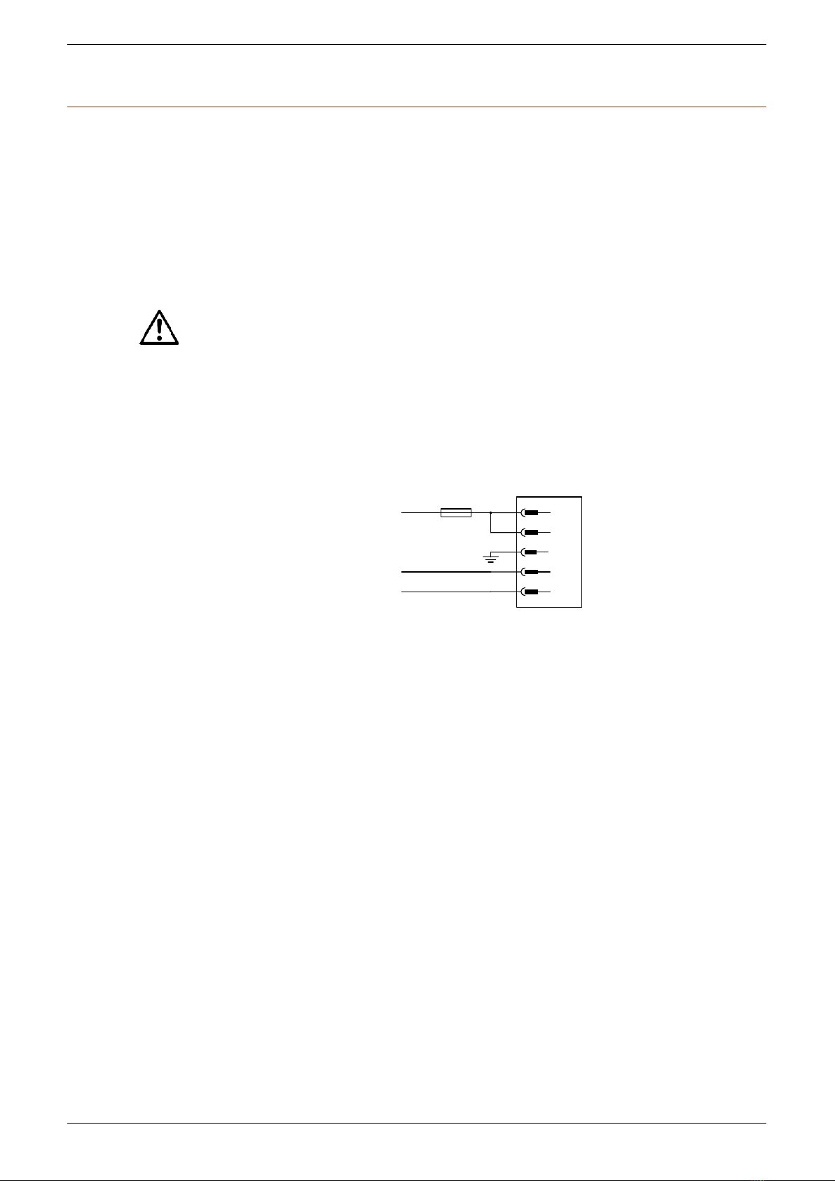
CN1 provides a power supply connection on the I/O module via a 5-way removable terminal
block, which is used for all inputs and outputs. A 24 VDC output is derived from this input
power supply connection and provided on the terminals for energising each of the standard
inputs. Each of these 24 VDC outputs has an on-board 5 Amp fuse. Should this current be
exceeded and the fuse triggered, the fuse can be reset by removing the power to the I/O
module and then re-applying.
The power supply input connection allows for 15 A maximum current for the I/O module.
Caution:
To ensure that the power supply chosen has the required current capability and the
maximum current for these inputs is not exceeded, it is important to give careful
consideration to the amount of current to be drawn by the outputs and supply
voltages from the I/O module.
A power supply LED indicator displaying the status of the power connection is located adjacent
to CN1. Connections are shown in Figure 2-1 below.
24VDC
24VDC
PE
0VDC
FIO04 –CN1
1
2
3
4
0VDC
5
24 VDC Supply
0 VDC Supply
0 VDC Supply
15A
Figure 2-1: PCSS-F Series I/O Module Power Connections
Power Supply Specifications
Input points
2
Input voltage
24 VDC ± 10%
Input current
15 A total
2
2.
.2
2
C
CN
N2
2
C
Co
on
nn
ne
ec
ct
ti
io
on
ns
s
CN2 has connections for outputs to control the solenoid valves on the press brake via a 7way
removable terminal block. These outputs are a combination of three dual outputs (Y00 to Y02)
and one standard outputs (Y03).
2
2.
.3
3
C
CN
N3
3
C
Co
on
nn
ne
ec
ct
ti
io
on
ns
s
CN3 houses connections for an Emergency Stop contactor with feedback via an 8-way
removable terminal block. A single dual output (Y04) and pulsed input combination (X00 / P00)
is available for these connections.
2
2.
.4
4
C
CN
N4
4
C
Co
on
nn
ne
ec
ct
ti
io
on
ns
s
Foot switches, up and down and error reset switch connections are available on CN4 via a 14-
way removable terminal block. The connections consist of two pulsed input combinations (X01
to X02 / P01 to P02) and seven standard inputs (X03 to X09). A 24 VDC connection is also
provided for energising when switched to the standard input.

PCSS-F Additions Technical Manual LS-CS-M-023
Page 2-2
Original Language Version: 1.02 Released: 03/12/2013
2
2.
.5
5
C
CN
N5
5
C
Co
on
nn
ne
ec
ct
ti
io
on
ns
s
Connections on CN5 are provided for Door and Emergency Stop switches on the press brake
via an 8-way removable terminal block. Three pulsed input combinations (X10 to X13 / P10 to
P13) are available for these connections. A 24 VDC connection is also available for energising
when switched to the standard input.
2
2.
.6
6
C
CN
N6
6
C
Co
on
nn
ne
ec
ct
ti
io
on
ns
s
CN6 houses connections for the level switches via a 12-way removable terminal block. Three
sets of pulsed inputs (X14 to X16 / P14 to P16) and three standard inputs (X17 to X19) are
available for connection. CN6 also contains a 24 VDC connection for energising when
switched to the standard input.
2
2.
.7
7
C
CN
N7
7
C
Co
on
nn
ne
ec
ct
ti
io
on
ns
s
Valve monitor input connections are available on CN7 via a 15-way removable terminal block.
These connections consist of a single pulsed input (X20 / P20) and eleven standard inputs
(X21 to X31). A 24 VDC connection is also provided for energising when switched to the
standard input.
2
2.
.8
8
C
CN
N8
8
C
Co
on
nn
ne
ec
ct
ti
io
on
ns
s
CN8 houses the connections that are required for the special user mode via a 4-way
removable terminal block. These connections consist of a single pulsed input (X32 / P32) and
one standard input (X33). A 24 VDC connection is also provided for energising when switched
to the standard input.
2
2.
.9
9
C
CN
N9
9
C
Co
on
nn
ne
ec
ct
ti
io
on
ns
s
CN9 houses the connections that are required for hand button control (Normally Closed
Contacts) via a 10-way removable terminal block. These connections consist of four pulsed
input (X34 to X37 / P34 to P37). A 24 VDC connection is also provided for energising when
switched to the standard input.
2
2.
.1
10
0
C
CN
N1
10
0
C
Co
on
nn
ne
ec
ct
ti
io
on
ns
s
CN10 houses the connections that are required for hand button control (Normally Open
Contacts) via a 9-way removable terminal block. These connections consist of four standard
inputs (X38 to X41) and two standard outputs (Y08 and Y09). A 24 VDC connection is also
provided for energising when switched to the standard input.

LS-CS-M-023 PCSS-F Additions Technical Manual
Page 2-3
Original Language Version: 1.02 Released: 03/12/2013
2
2.
.1
11
1
I
I/
/O
O
M
Mo
od
du
ul
le
e
S
Sp
pe
ec
ci
if
fi
ic
ca
at
ti
io
on
ns
s
Standard Input Specifications
Input voltage
24 VDC ± 10%
Input current
15 mA
Voltage on
14 VDC minimum
Voltage off
12 VDC maximum
Delay on
0.02 ms
Delay off
0.02 ms
Isolation
Opto-coupler
On display
Red LED
Output supply voltage
24 VDC ± 10%
Max supply current
5 A
Pulsed Input Specifications
Inputs
Input voltage
24 VDC ± 10%
Input current
15 mA
Voltage on
14 VDC minimum
Voltage off
12 VDC maximum
Delay on
0.02 ms
Delay off
0.02 ms
Isolation
Opto-coupler
On display
Red LED
Pulsed Outputs
Switching voltage
24 VDC ± 10%
Max switching current
1.6 A
Leakage current
0 mA
Isolation
Opto-coupler
On display
Red LED
Dual Output Specifications
Switching voltage
24 VDC ± 10%
Max switching current
10 A Peak, 4.5 A Continuous
Leakage current
0 mA
Delay on
0.11 ms max
Delay off
0.16 ms max
Isolation
Opto-coupler
On display
Red LED
Standard Output Specifications
Switching voltage
24 VDC ± 10%
Max switching current
6 A Peak, 1.6 A Continuous
Leakage current
0 mA
Delay on
0.11 ms max
Delay off
0.16 ms max
Isolation
Opto-coupler
On display
Red LED


LS-CS-M-023 PCSS-F Additions Technical Manual
Page 3-1
Original Language Version: 1.02 Released: 03/12/2013
3
3
C
CN
NC
C
P
Pr
re
es
ss
s
C
Co
on
nt
tr
ro
ol
ll
le
er
r
C
Co
om
mm
mu
un
ni
ic
ca
at
ti
io
on
ns
s
I
In
nt
te
er
rf
fa
ac
ce
e
3
3.
.1
1
S
Se
er
ri
ia
al
l
C
Co
om
mm
mu
un
ni
ic
ca
at
ti
io
on
ns
s
I
In
nt
te
er
rf
fa
ac
ce
e
O
Op
pt
ti
io
on
n
(
(s
se
er
r4
4_
_a
a9
9)
)
ISaGRAF driver
Driver name
ser4__a9
Driver description
Characteristics as shown below
Channel #
Description
0
Protocol options (4 = LzsBus2)
1
Baud rate option (0 = 9600; 1 = 19200; 2 = 38400; 3 = 57600; 4 =
76800; 5 = 115200bps)
2
Number of data bits (5, 6, 7 or 8)
3
Parity option (0 = None; 1 = Odd; 2 = Even)
4
Number of stop bits (1 or 2)
5
Hardware flow control (0 = Disabled; 1 = Enabled)
6
Non-zero: Reset all counts in ComErr board
Table 3-1: Analogue communication parameter outputs (ComParam)
Channel #
Description
0
Low level overrun error count
1
Low level framing error count
2
Low level parity error count
3
Invalid packet header count
4
Reserved
5
Checksum or CRC error count
6
Reserved
7
Reserved
8
Receive software buffer full error count
9
Receive synchronisation error count
Table 3-2: Analogue communications error count inputs (ComErr)

PCSS-F Additions Technical Manual LS-CS-M-023
Page 3-2
Original Language Version: 1.02 Released: 03/12/2013
Channel #
Units
Description
0
microns
Reference Y1
1
microns
Reference Y2
2
microns
Material thickness
3
microns
Die 01 height
4
microns
Die 02 height
5
microns
Punch 01 height
6
microns
Punch 02 height
7
microns
Tool reference
8
microns
CNC Mute position
9
microns
Upstand height
10
microns
Height of crowning
11
N/A
Reserved
12
microns
Decompression end height
Table 3-3: Analogue inputs received from the CNC (An_in)
Channel #
Units
Description
0
microns
Mute position calculated by PCSS
1
N/A
Condition code from PCSS
Table 3-4: Analogue outputs sent by the PCSS (An_out)
Channel #
Description
0
Normal Mode
1
Tray Mode
2
Stop at Mute Mode
3
Reserved
4
Tool 2
5
Reserved
6
Controller (CNC) Not Referenced
7
Reserved
8
Robot Mode
9
Mode 2 foot - 2 foot
10
Mode 1 foot –1 foot
11
Mode 2 hand –1 foot
12
Mode 2 hand –2 hand
13
Mode 4 hand –2 foot
14
Mode 4 hand –4 hand
15
Power Up Parameters
16-31
Reserved
Table 3-5: PCSS operation parameters from the CNC (OperMode)
Note:
The highlighted fields above are used by the PCSS kernel software directly from the
serial communications so these should not be changed or modified.
LS-CS-M-023 PCSS-F Additions Technical Manual
Page 3-3
Original Language Version: 1.02 Released: 03/12/2013
Channel #
Description
0
CNC OK
1
CNC TDC
2
CNC Mute
3
CNC Axis in Position
4
CNC Moving Up
5
Spare
6
CNC 2 Station
7
CNC Hydraulics On
8
Spare
9
Spare
10
Foot Station 1
11
Foot Station 2
12
Foot Station 3
13
Foot Station 4
14
CNC Referenced
15
CNC Decompression
16
CNC Hydraulic Start
17-23
Spare
Table 3-6: CNC Status (CNC_ST)
Note:
The highlighted fields above are used by the PCSS kernel software directly from the
serial communications so these should not be changed or modified.
Channel #
Description
0-2
Spare
3
Down high speed (down enable option 16 only)
4
Down low speed (down enable option 16 only)
5-14
Spare
15
Condition changed
16-23
Spare
Table 3-7: PCSS Status to the CNC (PCSS_ST)
Note:
The highlighted fields above are used by the PCSS kernel software directly from the
serial communications so these should not be changed or modified.
Channel #
Description
0-31
Spare
Table 3-8: Generic Analog inputs (gA_in)
Channel #
Description
0-31
Spare
Table 3-9: Generic Analog outputs (gA_out)

PCSS-F Additions Technical Manual LS-CS-M-023
Page 3-4
Original Language Version: 1.02 Released: 03/12/2013
Channel #
Description
0-127
Spare
Table 3-10: Generic Digital inputs (gD_in)
Channel #
Description
0-127
Spare
Table 3-11: Generic Digital outputs (gD_out)

LS-CS-M-023 PCSS-F Additions Technical Manual
Page 4-5
Original Language Version: 1.02 Released: 03/12/2013
4
4
P
PC
CS
SS
S
S
Sa
af
fe
et
ty
y
F
Fu
un
nc
ct
ti
io
on
n
O
Op
pt
ti
io
on
ns
s
4
4.
.1
1
D
Do
ow
wn
n
E
En
na
ab
bl
le
e
S
Sa
af
fe
et
ty
y
F
Fu
un
nc
ct
ti
io
on
n
O
Op
pt
ti
io
on
ns
s
These options enable and control movement of the pressing beam when initiated by the
operator of the press brake. The down enable function option to be selected will depend on the
solenoid valve control strategy needed, which is based primarily on the hydraulic configuration
of the press brake on which the PCSS is being installed.
It is therefore important to review the hydraulic configuration and schematic for the machine
and determine the down enable function option that is required. Selecting the appropriate
down enable option should be based on the solenoid valve outputs that need to be controlled
and the control strategy for each of these outputs.
I/O channel 9 of the ANO I/O board for the Kernel Software Interface allows the down enable
option required to be selected. Entering the appropriate value for the Down Enable Option
Selection Variable as detailed in each of the options described below will initialise the desired
down enable option when the PCSS software is started.
Note:
Lazer Safe recommends varistor protection is fitted across all valves installed on the
press brake when connected to the PCSS. Whilst resistor/capacitor and diode
protection solutions are available, varistor protection provides superior reaction time
and suppression capabilities to generated valve voltages and transients compared to
other protection solutions. The varistor also provides protection for valves with
integrated electronics as well as reducing EMI/RFI.
Resistor/capacitor protection modules can also interfere with the hardware checks
that are performed by the PCSS on the outputs on each machine cycle causing
incorrect failure conditions to be reported.
The use of diode type protection modules can also have an effect on the stopping
performance of the press brake. This may lead to increased stopping distances or
times compared to the use of Varistor protection.
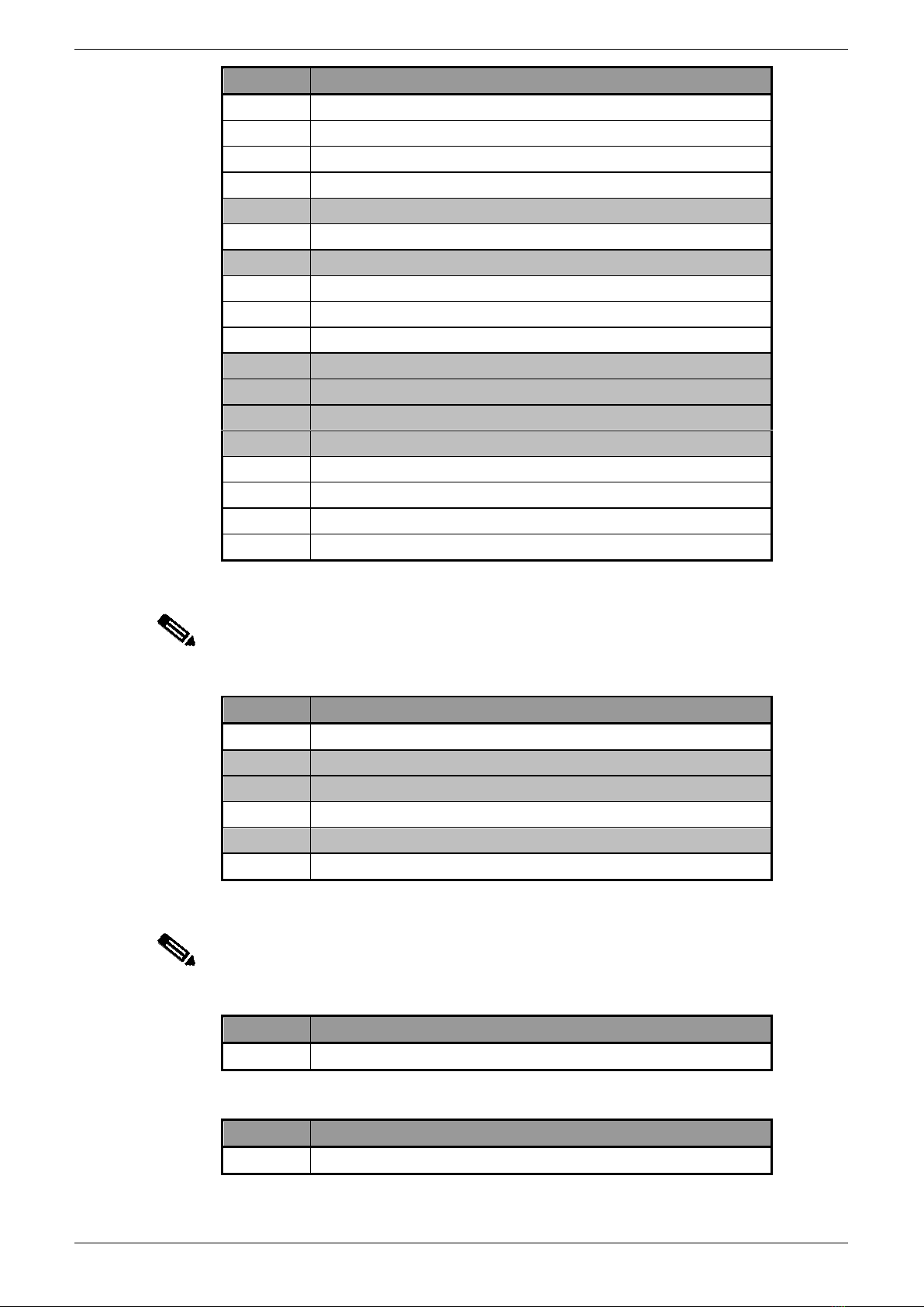
4.1.1 Down Enable Option 16
Solenoids –High Speed
Solenoids –Prefill
Solenoids –Proportional Enable
Y00H
Y00L
Y01H
Y01L
Y02H
FIO04 –CN2
1
2
3
4
5
Y02L
6
Y03
7
Figure 4-1: Down Enable Option 16 (CN2 - FIO04 Connections)
This down enable option provides outputs for control of the following solenoid valves on the
press brake:
•High Speed Solenoid;
•Low Speed Solenoid and;
•Proportional Solenoids Enable.

PCSS-F Additions Technical Manual LS-CS-M-023
Page 4-6
Original Language Version: 1.02 Released: 03/12/2013
The down enable condition from the down enable option is not physically connected to an
output but is one of the conditions that must be met before down movement is allowed by the
PCSS. This condition used from the down enable option indicates that the down switch has
been pressed and that down movement of the pressing beam can occur due to the required
safety conditions being met.
The down low speed condition is enabled when slow speed operation is required, but as with
the down enable condition, it is not physically connected to an output. This condition is used to
indicate that slow speed down movement is enabled. Any of the following variables being set,
will cause a latched condition to be set which is not reset until the TDC input to the Kernel
Software interface is set:
•Pressing speed;
•Crawl speed;
•CNC mute has been reached;
•CNC controller has not yet been referenced;
•Pressing of the material has begun; or
•High speed disable distance before mute position has been reached.
When this latched condition and the down enable condition are both set, then the down low
speed condition will be enabled or set.
The outputs used on the PCSS for the solenoid valves on the press brake provided by this
option are detailed below with the connections shown in Figure 4-1 for the FIO04 module. The
operation of these solenoid valve outputs during up and down movement of the pressing beam
is shown in Figure 4-2.
The high speed solenoid output is connected to a safety output on the PCSS and allows the
control of the high speed solenoid valves on the press brake. If the down enable condition has
been met but the down low speed condition has not been enabled, the high speed solenoid
output will be switched on and the pressing beam can move down at high speed. This output
will be switched off when down low speed is required.
The down low speed condition is enabled when slow speed operation is required, but as with
the down enable condition, it is not physically connected to an output. This condition is used to
indicate that slow speed down movement is enabled. Any of the following variables being set,
will cause a latched condition to be set which is not reset until the TDC input to the Kernel
Software interface is set:
•Pressing speed;
•Crawl speed;
•CNC mute has been reached;
•CNC controller has not yet been referenced;
•Pressing of the material has begun; or
•High speed disable distance before mute position has been reached.
When this latched condition and the down enable condition are both set, then the down low
speed condition will be enabled or set.
The proportional pressure output from the down enable option is set once the hydraulic pump
is running and if:
•The down enable condition is set; or
•The decompression command has been received from the CNC press controller; or
•The up command has been received from the CNC press controller after decompression.

LS-CS-M-023 PCSS-F Additions Technical Manual
Page 4-7
Original Language Version: 1.02 Released: 03/12/2013
It is also possible to have an additional delay when the proportional pressure output is switched
off from the PCSS by using a variable connected to I/O channel 23 of the ANO board for the
Kernel Software Interface.
The proportional enable output is used to enable the proportional solenoid on the press brake
and is connected to a standard output. Once the pump is running, this output remains on when
the down enable is on and is disabled if the CNC press controller has initiated the up command
after decompression.
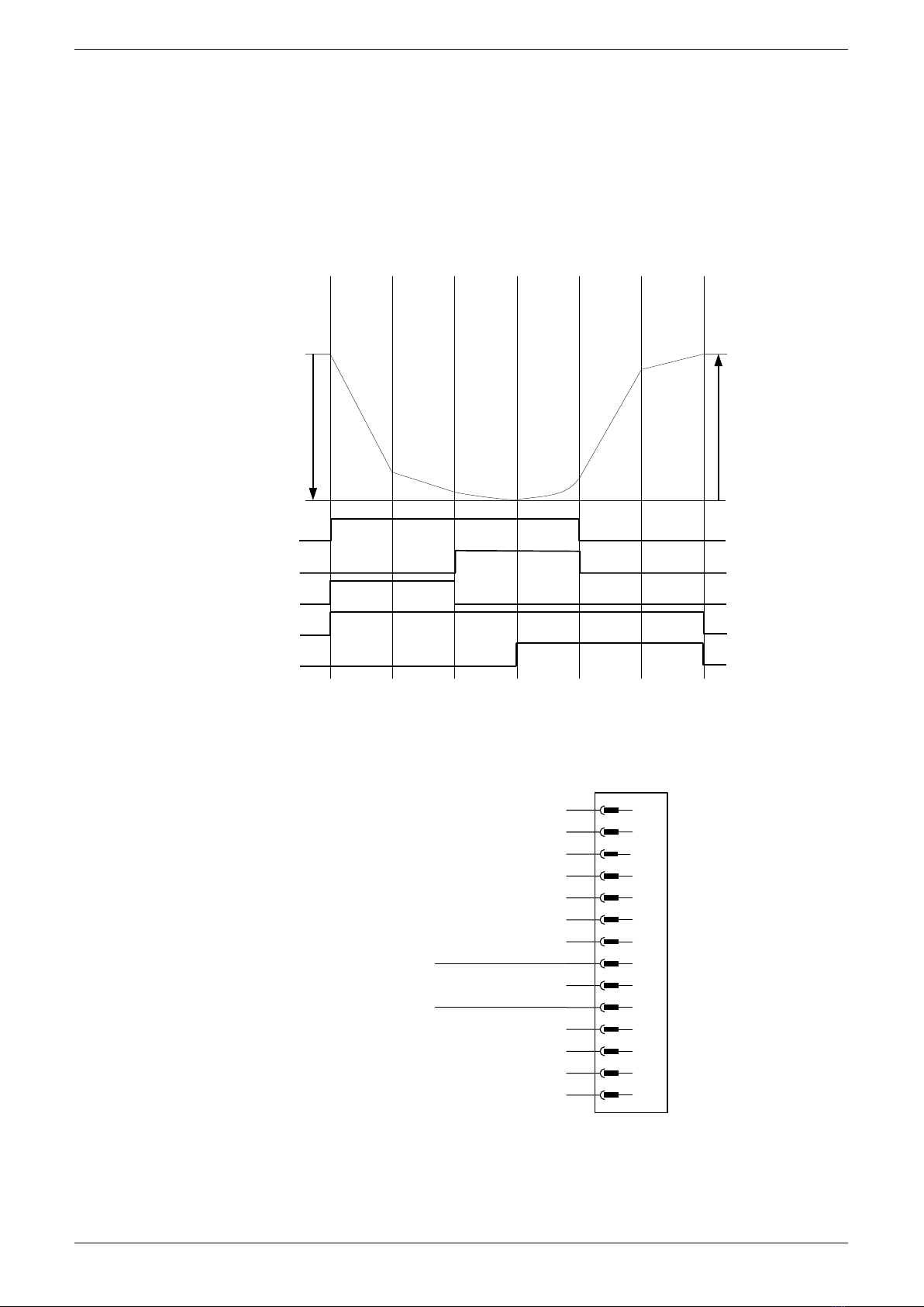
1
0
1
0
1
0
1
0
TDC
BDC
RAPID SPEED
DOWN
TDC
BDC
DOWN ENABLE
DOWN LOW SPEED
FIO04 – Y01
DOWN HIGH SPEED
FIO04 – Y00
PROPORTIONAL ENABLE
FIO04 – Y03
DECELERATION
RAMP
PRESSING
DECOMPRESSION
RAPID SPEED
UP
SLOW STOP
POSITION
Figure 4-2: Down Enable Option 16 Output Operation
4.1.1.1 Option Selection
To select down enable option 16 during the PCSS configuration, set the initial value for Down
Enable Option Selection Variable to 16 as described the PCSS F Series Technical Manual.
This will ensure that this option and all required outputs are initialised when the PCSS software
is started.
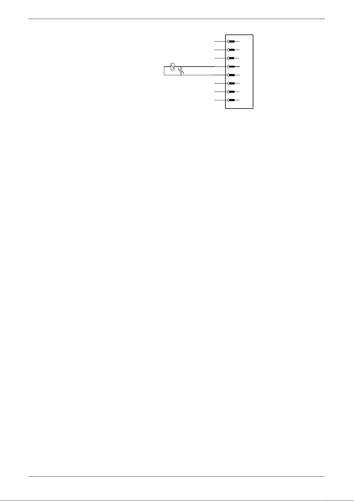
4.1.2 Down Enable Option 17
Brake Set Y1-2
Quickstop
Y00H
Y00L
Y01H
Y01L
Y02H
FIO04 –CN2
1
2
3
4
5
Y02L
6
Y03
7
Brake Set Y1-1
Brake Set Y2-1
Figure 4-3: Down Enable Option 17 (CN2 - FIO04 Connections)
PCSS-F Additions Technical Manual LS-CS-M-023
Page 4-8
Original Language Version: 1.02 Released: 03/12/2013
Brake Set Y2-2
X00
X01
X02
Y04H
Y04L
FIO04 –CN3
1
2
3
4
5
Y05
6
P00
7
24VDC
8
Figure 4-4: Down Enable Option 17 (CN3 - FIO04 Connections)
This down enable option provides outputs for control of the following devices on the press
brake:
•Mechanical Brakes and;
•Electric Motor Quick Stop.
The down enable condition from the down enable option is not physically connected to an
output but is one of the conditions that must be met before down movement is allowed by the
PCSS. This condition used from the down enable option indicates that the down switch has
been pressed and that down movement of the pressing beam can occur due to the required
safety conditions being met.
The up enable condition is also controlled by this down enable option and although not
physically connected to an output, is one of the conditions that must be met before up
movement is allowed by the PCSS. This condition indicates that up movement of the pressing
beam can occur due to the required conditions being met.
The down low speed condition is enabled when slow speed operation is required, but as with
the down enable condition, it is not physically connected to an output. This condition is used to
indicate that slow speed down movement is enabled. Any of the following variables being set,
will cause a latched condition to be set which is not reset until the TDC input to the Kernel
Software interface is set:
•Pressing speed;
•Crawl speed;
•CNC mute has been reached;
•CNC controller has not yet been referenced;
•Pressing of the material has begun; or
•High speed disable distance before mute position has been reached.
When this latched condition and the down enable condition are both set, then the down low
speed condition will be enabled or set.
The down high speed condition is enabled when high speed operation is required, but as with
the down enable condition, it is not physically connected to an output. This condition is used to
indicate that high speed down movement is enabled. The following conditions must be satisfied
for high speed down movement:
•Moving Down;
•Down Enable active and;
•Down Low Speed is disabled.
LS-CS-M-023 PCSS-F Additions Technical Manual
Page 4-9
Original Language Version: 1.02 Released: 03/12/2013
The quick stop condition is enabled during up and down movement during normal operation
or when the static brake tests are performed on the machine. When the beam is moving
down and the dynamic brakes tests are active the quick stop condition is disabled for
determining the stopping performance of the mechanical brakes during down movement.
The outputs used on the PCSS for the mechanical brakes are shown in Figure 4-3 and
Figure 4-4 for the FIO04 module. The operation of the mechanical brakes occurs during
emergency braking and stopping of the machine in conjunction with the quick stop output.
1
0
1
0
1
0
1
0
1
0
TDC
BDC
RAPID SPEED
DOWN
TDC
BDC
DOWN ENABLE
DOWN LOW SPEED
DOWN HIGH SPEED
DECELERATION
RAMP
PRESSING
DECOMPRESSION
RAPID SPEED
UP
SLOW STOP
POSITION
QUICKSTOP
UP ENABLE
Figure 4-5: Down Enable Option 17 Output Operation
4.1.2.1 Down Low and High Speed Outputs
X03
X04
X05
X06
X07
FIO04 –CN4
1
2
3
4
5
X08
6
X09
7
Y06
8
0VDC
9
Y07
0VDC
P03
10
11
12
P04
13
24VDC
14
Down Low Speed
Down High Speed
Figure 4-6: Down Enable Option 17 (CN4 - FIO04 Output Connections)
When the Down Enable Option Selection Variable is set to 17 on the PCSS, with FIO04
hardware installed, the Y06 output is configured as the kernel down low speed, k_lsd and the
Y07 output is configured as the kernel down high speed, k_hsd.

PCSS-F Additions Technical Manual LS-CS-M-023
Page 4-10
Original Language Version: 1.02 Released: 03/12/2013
4.1.2.2 Option Selection
To select down enable option 17 during the PCSS configuration, set the initial value for Down
Enable Option Selection Variable to 17 as described the PCSS F Series Technical Manual.
This will ensure that this option and all required outputs are initialised when the PCSS software
is started.
Table of contents
Popular Safety Equipment manuals by other brands

Micro Detectors
Micro Detectors LS2 Series Installation and operation manual

Petzl
Petzl TIKKA manual

Merlino
Merlino RED-RL Series user manual

BUCKINGHAM MFG
BUCKINGHAM MFG BuckSqueeze 483 Series Instructions & warnings

Kapriol
Kapriol 32560 Instruction and Information Manual

Climbing Technology
Climbing Technology ORBITER F instruction manual


Westward
Westward 2MZU5 Operating instructions and parts manual

Guardian
Guardian G-SAL instruction manual

Singing rock
Singing rock FOOTER II quick start guide

SICK
SICK safeRS operating instructions

EUCHNER
EUCHNER LCA 2 Series operating instructions

Campbell
Campbell Advisor Guide Pedestrian Signal user manual