Merlino RED-RL Series User manual

USER MANUAL
Designed and produced in accordance with EEC directives
MISU-RED-RL-UK 1.0 - Revision 1.0 of 27 March 2017
MERLINO elettronica s.a.s. di Meroni N.
Via Como, 33/A - 20851 Lissone - MB
E-mail: [email protected]
Web-site: www.merlinoelettronica.it
ITALIA-UE Tel & Fax ++39-039-2450296
Partita I.V.A. e Codice Fiscale 03398650964
Pag. 1
MISU-RED-RL-UK-1.0
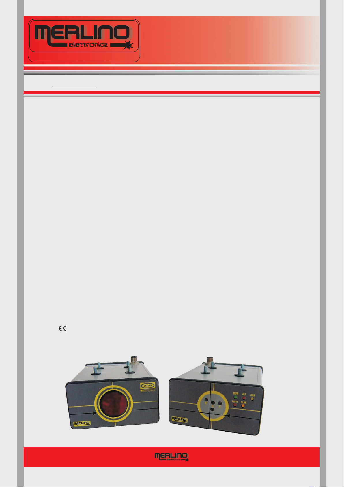
“RED-RL”
SERIES
ACTIVE OPTOELECTRONIC
PROTECTIVE DEVICE “AOPD”
AT LASER EMISSION
PREFACE
This manual provides the user and/or installer with the information required for correct use
of the "RED-RL" device in the application for which it was designed, and in safety and risk-
prevention.
The manual must be kept carefully in such a way as to be immediately available should it be
required.
Contact the manufacturer for clarification, explanations or additional copies or updates of
the manual itself.
The manufacturer reserves the right to vary products and the manual without being
obliged to update previous products and manuals.
2006/42
CONTENTS
2
Pag. 2
DESIGN AND MANUFACTURE
OF ELECTRONIC EQUIPMENT
MERLINO elettronica s.a.s. di Meroni N.
Via Como, 33/A - 20851 Lissone - MB
E-mail: [email protected]
Web-site: www.merlinoelettronica.it
PAG.1
PAG.2
PAG.3
PAG.4
PAG.5
PAG.6
PAG.7
PAG.8
PAG.9
PAG.10
PAG.11
PAG.12
PAG.13
PAG.14
PAG.15
PAG.16
TX RX
1. Preface ......................................................................................
2. Contents ...................................................................................
3. Warranty - Attendance - Supplied material .........................
4. Legend - Verifying the protected area..................................
5. Introduction - Installation......................................................
6. Chosen of the Device - Precautions ....................................
7. Available functions ..................................................................
8. Light indicators and setting controls - RX ............................
9. Rating plate - Indications.......................................................
10. Determining the safe distance ...............................................
11. Technical characteristics ........................................................
12. Electrical connections - TX .....................................................
12.1 Electrical connections - RX ....................................................
13. Mechanical data .......................................................................
14. Maintenance and controls - Spare parts ..............................
15. declaration of conformity ..................................................
MISU-RED-RL-UK-1.0
WARRANTY - ATTENDANCE - MATERIAL SUPPLIED AS STANDARD
3
1)
2)
3)
4)
5)
MERLINO elettronica s.a.s. di Meroni N.
Via Como, 33/A - 20851 Lissone - MB
E-mail: [email protected]
Web-site: www.merlinoelettronica.it
The warranty
ATTENDANCE
MATERIALSUPPLIEDASSTANDARD
is valid for a period of 12 months from the consignment date and expires at the
end of this period, irrespective of whether the appliance has in fact been used. The guarantee
covers all parts of the device if the materials or assembly of said parts are shown to be faulty and
in respect of the following conditions:
The warranty covers replacement of all those parts shown to be of faulty manufacture
under normal conditions of use.
The warranty is not valid unless accompanied by a copy of the invoice proving purchase.
The warranty is not valid in the following cases:
a - if the device has been tampered with in any way;
b - use of the device in ways not conforming to the instructions and warnings
given in this manual;
c - damage caused by an unsuitable working environment or phenomena not
dependent on normal operation (e.g. an unsuitable mains voltage and/or
frequency values);
d - repairs carried out by persons or technical assistance centres not authorised
by the manufacturer.
The resulting costs and risks associated with transport, packing and labour are the
responsibility of the purchaser.
The replacement of the device and/or extension of the period of guarantee validity
following a fault are excluded.
Compensation will not be paid for damages occurring as a result of the device being
inoperative while repairs are carried out.
Where not explicitly specified, reference should be made to 85/374/EEC on the
responsibility for faulty products as incorporated in Italian Decree D.P.R. 224 of 1998.
The servicing, meant like informative support of answer to any type of relating clarification the
device in object, and the repairs are supplied directly from the manufacturer.
The "RED-RL" optoelectronic active laser light curtain, consists of the following elements sup-
plied suitably packed:
- Transmitter (TX) complete with M12 - 5 pole output connector with 5 m long cable
- Receiver (RX) complete with M12 - 8 pole output connector with 5 m long cable
- Copy of the present manual including the “ DECLARATION OF CONFORMITY”
- Cylindrical Test Piece to verify the integrity of the declared detection capability
Pag. 3
DESIGN AND MANUFACTURE
OF ELECTRONIC EQUIPMENT
MERLINO elettronica s.a.s. di Meroni N.
Via Como, 33/A - 20851 Lissone - MB
E-mail: [email protected]
Web-site: www.merlinoelettronica.it
MISU-RED-RL-UK-1.0

4LEGEND - NORMATIVE REFERENCES - VERIFICATIONS
MERLINO elettronica s.a.s. di Meroni N.
Via Como, 33/A - 20851 Lissone - MB
Web-site: www.merlinoelettronica.it
VERIFYING THE PROTECTED AREA
This should be performed using a cylindrical Test Piece with a diameter corresponding to the
detection capability of the device concerned. This must be intercepted anywhere within the
protected area, causing the green LED to light-off and the red LED to light-on.
The Output Signal Switching Devices (OSSDs) should also open, disabling operation of the
machine. A Test Piece, suitable for the device in use, should always be available near the work
station, to allow the every day verification.
RUN ALT
=
=Elettro Sensitive Protective Equipment
Output Signal Switching Device
= Trans
)
= R
= state of temporary neutralization of the protecting action of the
device
= state of temporary neutralization of a part of the protecting
action of the device
=
= zone inside of which the specific test piece is intercepted from
the device
= minimal dimension of the test cylinder that is anywhere
intercepted from the device within the survey zone
=
= state in which the Output Signal Switching Devices OSSDs are
open
= state in which the Output Signal Switching Devices are closed
=
=650 nm
name of the device covered by this manual
mitter (section of the “RED-RL” light guard emitting
LASER radiation with a wavelength of
eceiver (section of the "RED-RL" light guard acting as a
sensor and command and control device and incorporating the
two OSSDs).
component monitoring the contacts efficiency of devices
connected externally to the outputs of the light guard ( xternal
evice onitor).
E
D M
the maximum time that elapses between the occlusion of the
laser bundle and the switching OFF of the utput ignal
witching evices OSSDs
O S
S D
RED4RL
ESPE
OSSD
TX
RX
MUTING
BLANKING
PROTECTED AREA
DETECTION CAPABILITY
RESPONSE TIME
ON STATE
OFF STATE
NORMATIVE REFERENCES
UNI-EN 12622
The intangible Barrier with Laser emission has been designed and manufactured
following the indications supplied from ESPE Elettro Sensitive Protective
Equipment” and AOPD Active Opto Electronic Protective Devices” normes,
and is classifiable as ESPE of TYPE 2 or TYPE 4. The device is also in compliance with the
paragraph 5.3.2. - f) and 5.3.12 of the norm “Hydraulic Press Brakes”. The visible
and modulated Laser light source, emitted from the Transmitter (TX) section, having an intensity
so much limited (approximately 1mW) is classified as safety CLASS 2 as the .
“RED-RL”
“
“
CEI-EN 61496-1
CEI-EN 61496-2
IEC EN 60825
Pag. 4
DESIGN AND MANUFACTURE
OF ELECTRONIC EQUIPMENT
MERLINO elettronica s.a.s. di Meroni N.
Via Como, 33/A - 20851 Lissone - MB
E-mail: [email protected]
Web-site: www.merlinoelettronica.it
EDM
MISU-RED-RL-UK-1.0

5INTRODUCTION - INSTALLATION
MERLINO elettronica s.a.s. di Meroni N.
Via Como, 33/A - 20851 Lissone - MB
Web-site: www.merlinoelettronica.it
The safety device “RED-RL” is an intangible Barrier with a visible light laser emission that in
coupling to the machine control system supplies protection from accidents to the operator uses
in it of the same one. It is composed by a Transmitter (TX) and a Receiver (RX) . The Control
Logic of the Receiver drives the two outputs to the active state ON when all the sensing elements
are illuminated from the red light laser emitted from the Transmitter, while the outputs are drived
to the inactive state OFF in the event in which the intrusion of any opaque element inside of the
survey area it prevents that just one of the sensing elements can be illuminated from the laser
light beam. The function of the device is therefore that to inhibit to the command elements of the
machine the consent to the operation in the moment in which there are not the safety conditions
to operate. Any improper use of the device must be thought thus prohibited cause the
consequent loss of any form of explicit and implicit warranty, like every responsibility from the
manufacturer for eventual damages and accidents that could be taken place.
In order that the laser guard “RED-RL” can work in the more appropriate way it is fundamental that
it is correctly installed, tested and used as it follows.
INSTALLATION
units
The "RED-RL" device has been designed and manufactured with the aim of eliminating or
reducing as far as possible all risks for the user. However, could result in
unforeseen conditions with some degree of danger which cannot be completely eliminated.
Installation, testing and maintenance of the "RED-RL” device must be performed exclusively by
qualified personnel following the instructions in this manual faithfully and meticulously.
Ensure the two units, Transmitter (TX) and Receiver (RX), are perfectly parallel, and fixed, using
the supplied means, at the working distance specified when ordering and reported on the rating
plate under the heading "Working Distance". Keep the Receiver out of direct sunlight. The
equipment is turned on by powering the transmitter TX and receiver RX according to the
information given on the rating plate. After about one second the device should be ready for
operation.
The meaning of the light indicators is described and illustrated in detail in paragraph 8
". After turning power to the two units on, and aligning them
correctly, make sure that the green indicator on the Receiver is on. The red indicator,
on the RX, lights on in the presence of an obstacle inside the protected area or if the units are not
perfectly aligned. To prolong the connections, use shielded cable to avoid any kind of
interference. If there are shiny reflectant surfaces near the light curtain, they should ideally be
coated with matt black paint to reduce the risk of undesirable reflections.
At the end of the installation, also verify correct operation of the devise using the test piece to
ensure it is intercepted at all points of the area to be protected. The minimum diameter of the test
piece unequivocally intercepted at all points of the protected area is known as the Maximum
Detection Capability (from CEI-EN 61496 standard) of the light curtain. For example, for the
“RED-RL” series this is greater or equal to14 mm.
improper use
"Light
indicators and setting controls - RX
From the frontal head of TX section a visible light laser beam has to come out and has
to illuminate the frontal head of RX section with references for the correct alignment in
correspondence of the four light incoming holes to the sensors (Pag.9 - Fig.9). Eventually
improve the alignment of the two sections in the event the laser beam did not have to perfectly
illuminate the zone of the references.
RUN ALT
Pag. 5
DESIGN AND MANUFACTURE
OF ELECTRONIC EQUIPMENT
MERLINO elettronica s.a.s. di Meroni N.
Via Como, 33/A - 20851 Lissone - MB
E-mail: [email protected]
Web-site: www.merlinoelettronica.it
MISU-RED-RL-UK-1.0

6CHOSEN OF THE DEVICE - PRECAUTIONS
MERLINO elettronica s.a.s. di Meroni N.
Via Como, 33/A - 20851 Lissone - MB
Web-site: www.merlinoelettronica.it
RED2-RL - RED4-RL
The choice between the two models must be made on the basis of the risk category attributed to
the machine, assessed in accordance with European standard . The
model is suitable for all applications with maximum accident risk, both in terms of the
frequency with which the operator is exposed to said risk and the gravity of the danger (machines
listed in annex IV of Directive 2006/42/EEC). The model is suitable for all other applica-
tions where the severity and frequency of exposure to the risk of accident is less.
To prevent shift of the laser light guard and consequently also of the protected area, it must be
fixed solidly and precisely respecting the instructions given in paragraph 13 "Mechanical Data".
so as
Connection cables must be arranged so as to avoid accidental contact with, for
example, abrasive, hot or sharp objects which could cause dangerous damage to the cables
themselves. In the event of damage to the connection cables, do not use the device and
disconnect immediately from the power supply. Avoid the connection cables coming into
contact with water or damp surfaces. In addition, prevent access to the danger zone with other
fixed material barriers where this is not possible by the use of electro sensitive protective devices.
The and housings are electrically connected to the ground of the internal circuit, thus to
the conductor of the connector. Contact between the housing and the chassis of the
machine (unless free of potential) must therefore be avoided. Failure to observe this precaution
could lead to damage of the units. This danger is totally avoided if the sensor units are correctly
fixed using special supports in electrically insulating material. Connection of other equipment to
the power source used to power the "RED-RL" device is not recommended. This could generate
electrical disturbance, jeopardising correct operation of the various parts of the device itself. If
liquid or foreign bodies of any kind penetrate into the device, stop using it immediately and
disconnect it from the power supply. The “RED-RL” device has been designed and produced in
such a way that the housing does not have to be opened for the device to be used. Given the
particular function of the device itself, removal of the heads of the aluminium housings of the
transmitter TX and receiver RX is prohibited. No attempt should be made to repair them. Always
contact the manufacturer only.
UNI/EN/ISO 13849-1
RED4-RL
RED2-RL
MECHANICALWARNINGS
ELECTRICALWARNINGS
TX RX
GND
It
has to be adopted every precaution in order to reduce at the minimum the vibrations of the
machine, protect the device and its supports with mechanical shelters to avoid direct
collisions.
Verify that the available power supply source corresponds to that operating one of the device in
use that must be verified from the data plate of both sections Transmitter (TX) and Receiver (RX).
The presence of a visible light laser emission, even if of low power as established by the enforced
european norms, could cause the use of the device dangerous. The protection of the person eye
from accidental flash turns out however assured, also without particular precautions, by the own
reactions defense like as an example the palpebral glare. It is however advised to avoid itself to
frontally fix or to direct the visible light laser source emitted from the Transmitter (TX).
OPTICALWARNINGS
Pag. 6
DESIGN AND MANUFACTURE
OF ELECTRONIC EQUIPMENT
MERLINO elettronica s.a.s. di Meroni N.
Via Como, 33/A - 20851 Lissone - MB
E-mail: [email protected]
Web-site: www.merlinoelettronica.it
MISU-RED-RL-UK-1.0

7AVAILABLE FUNCTIONS
MERLINO elettronica s.a.s. di Meroni N.
Via Como, 33/A - 20851 Lissone - MB
Web-site: www.merlinoelettronica.it
STARTRESTARTINTRLOCK
EXTERNAL DEVICE MONITOR
MUTING
RED-RL safety devices can be easily setted, without making any internal modifications, to switch
from the automatic restart to the manual restart operation with start-restart interlock by a remote
push-button (Pag.13 - Fig.15/16).
In automatic restart operation the Receiver control logic, without consents from the outside, auto-
matically drives the two output signal switching devices to the active ON state every time that the
laser beam emitted from the Transmitter catches up the four sensing elements of the Receiver af-
ter that the same one has been interrupted from an obstacle. Instead, in the event in which the de-
vice comes setted for manual restart operation, every time that the laser light beam comes inter-
rupted is necessary to supply, for example by a push-button or a safety-pedal, an external input si-
gnal on the respective dedicated YELLOW color conductor (see paragraph 12.1 “Electrical con-
nections - RX”) that it qualifies the control logic of the Receiver to bring back to the active ON sta-
te the output signal switching devices after a switching OFF of the same ones as a result of an in-
terruption of the laser light beam.
An External Device Monitor (EDM) control loop circuit allows, the safety RED-RL guard, to control
the state of the correct operation of the devices (eg. relé, contactors, etc) externally connected to
the two outputs as a load, thus extending the safety level up to the machine primary control
elements. To such scope the Receiver, of the laser guard, is provided of the YELLOW color input
conductor who make head to the inside EDM circuit.
Between this conductor and ground, “0V” of power supply, has to be in series connected the
normally open switches of the external output load devices thus from being able to test their own
efficiency as a consequence of every actuation (passage from ON to the OFF state) of the barrier
for the interruption of the laser beam. In the event in which such function it does not used, it is
necessary to connect the conductor YELLOW to the ground “0V” of power supply.
For the “RED4-RL” Laser guard model, the “Neutralization” or “Muting” function is also
previded, that is the possibility of being able to suspend in temporary way its own
protecting function. That it means that when the two dedicated inputs are simultaneously
activated (within a maximum time of 0,8 second) putting separately in short-circuit the
PINK and GRAY conductors to the “0V” of power supply (RED conductor and Shield), the
Laser Guard surveillance action comes temporarely neutralized, allowing that the Laser
beam can be darkened without that the output signal switching devices (OSSDs) switch
to the inactive OFF state. A red color blinking signaler, situated on the top head of the “RX”
section (Pag.8), shows the activation of the Muting function. In the event of the two
dedicated muting inputs are not simultaneously activated, or however with a time delay
more than 0,8 second, the RED4RL switches into the block state opening the output
signal switching devices (OSSDs) and signaling it as the “D” case of the diagnostic table of
Pag 8.
. Adopt a visual and/or acoustic to indicate in
unequivocal way the inactivity state of the Barrier to activated Muting.
Make attention using this function as it could generate potentially dangerous
situations additional external signaler
Pag. 7
DESIGN AND MANUFACTURE
OF ELECTRONIC EQUIPMENT
MERLINO elettronica s.a.s. di Meroni N.
Via Como, 33/A - 20851 Lissone - MB
E-mail: [email protected]
Web-site: www.merlinoelettronica.it
MISU-RED-RL-UK-1.0
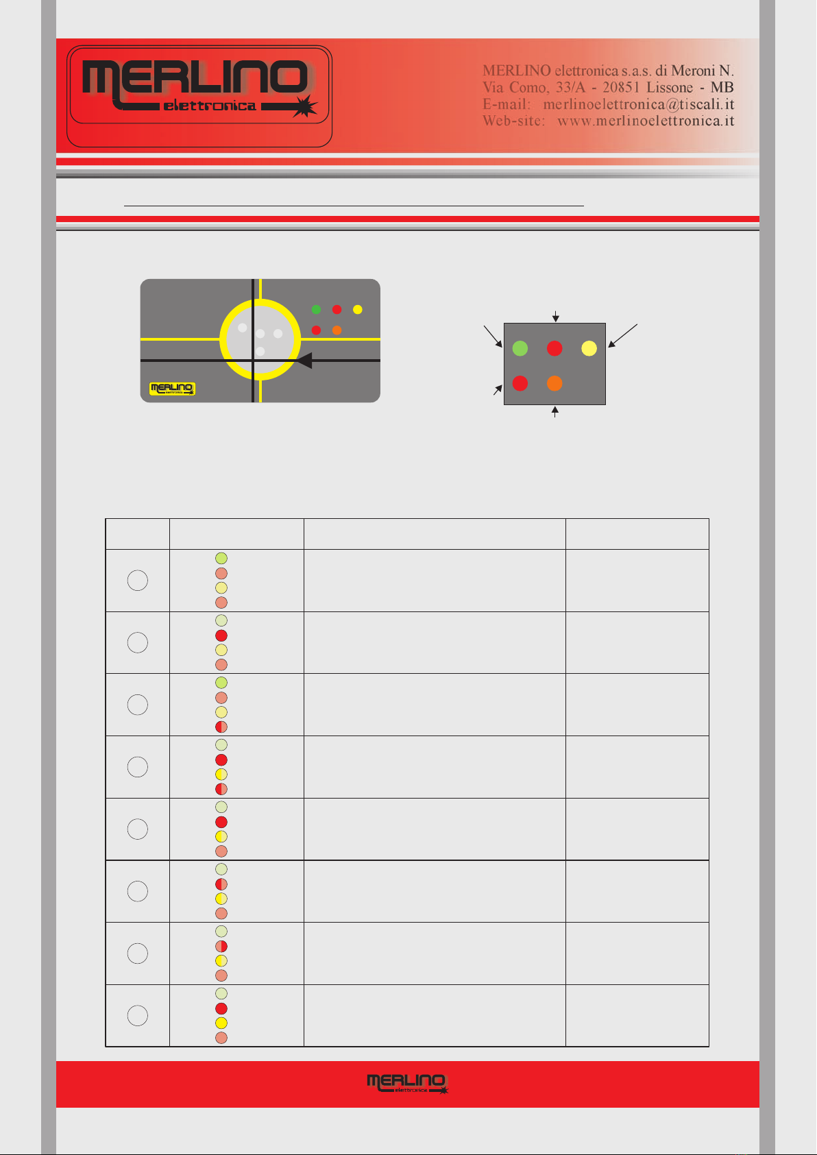
LIGHT INDICATORS and SETTING CONTROLS - RX
8
RX - FRONT PANEL
orange colored setting indicator of the operation mode with
"Blanking", then with the exclusion of two sensors "Front" (F)
and "Rear" (R). It lights by disconnecting from the "0V" of the
power supply the green colored wire.
Fig.1
MUTE BLNK
RUN BLKALT
Fig.2
MERLINO elettronica s.a.s. di Meroni N.
Via Como, 33/A - 20851 Lissone - MB
Web-site: www.merlinoelettronica.it
CF
R
MUTE BLNK
RUN BLKALT
BLNK
Pag. 8
DESIGN AND MANUFACTURE
OF ELECTRONIC EQUIPMENT
MERLINO elettronica s.a.s. di Meroni N.
Via Como, 33/A - 20851 Lissone - MB
E-mail: [email protected]
Web-site: www.merlinoelettronica.it
TROUBLESHOOTING
CHECK AND
SOLUTION
A
Disparity between the
inside driving channels
Block briefly
the protective curtain,
if persist send to factory
Load sinking current connected
to the OSSD1 or OSSD2 higher than 0,7A,
OSSD1 or OSSD2 short-circuited to GND
(RED4-RL model only)
FAST
SIMULTANEOUS
BLINKING
B
C
{
DEVICE STATUS
OSSD1 or OSSD2 connected to the +24Vcc
or OSSD1 short-circuited with OSSD2
(RED4-RL model only)
OSSD1 or OSSD2 connected to the +24V
during power-on
(RED4-RL model only)
D
LEDs STATUSCASE
BLINKING
ON
OFF
BLK
ALT
RUN
OFF
MUTE
E
F
G
H
OFF
OFF
ON
BLK
ALT
RUN
OFF
MUTE
OFF
ON
OFF
BLK
ALT
RUN
OFF
MUTE
OFF
OFF
ON
BLK
ALT
RUN
BLINKING
MUTE
BLINKING
ON
OFF
BLK
ALT
RUN
BLINKING
MUTE
ON
ON
OFF
BLK
ALT
RUN
OFF
MUTE
OFF
BLK
ALT
RUN
OFF
MUTE
OFF
BLK
ALT
RUN
OFF
MUTE
Optical alignment O.K.,
no obstacles
No failures
SLOW
ALTERNATE
BLINKING
{
No optical alignment
or obstacles presence
Possible internal fault
Improve the alignment,
remove probable obstacles.
If persist send to factory
MUTING activated, protective action
temporarely neutralized
(RED4-RL model only)
Warning,
possible unsafe
situation
Disparity state between the
inputs, or inputs activated
with obstacles presence
MUTING Check MUTING sources,
remove probable obstacles.
If persist send to factory
Switch-off power supply,
remove the factor,
switch-on power supply
Check if the
are in the ON state
OSSDs
Remove the factor
and block briefly the
protective curtain
Remove the factor
and block briefly the
protective curtain
Indicates exclusion
of some sensors of
the laser-guard
Indicates aligned
with
no
laser-guard
obstacles
Indicates misaligned
laser-guard or
obstacles presence Indicates
for failure
lockout
state laser-guard
Indicates neutralization
of the all sensors of the
laser-guard (MUTING)
MISU-RED-RL-UK-1.0

RATING PLATE - INDICATIONS
M12 - 5 poles male plug M12 - 5 poli spina maschio
If the function TEST is not used short circuit the conductors 4-5
Se la funzione TEST non viene utilizzata cortocircuitare i conduttori 4-5
1)
2)
3) /Blu
4) /Nero
Brown
White
Blue
Black
/Marrone
/Bianco
=
= Ref.
= GND
= Test
+ 24V 5) /GrigioGrey = Test
1 2
3
4
5
TX RED-RL
RX RED2-RL
RX RED4-RL
9
Fig.4
Fig.5
Fig.6
Fig.3
LASER RADIATION - AVOID
Class2 - P=1mW / 650nm=
DIRECT EYE EXPOSURE
Fig.7
Fig.8
Fig.9
TX RED-RL
TX RED-RL
RX RED-RL
MERLINO elettronica s.a.s. di Meroni N.
Via Como, 33/A - 20851 Lissone - MB
Web-site: www.merlinoelettronica.it
www.merlinoelettronica.it
Serial number
Numero di serie
Detection capab.
Capacità di rilev.
Model
Modello
1703025
Safety category
Categoria di sic.
Protected height
Altezza protetta
TYPE 4
12 mm
Supply voltage
Tensione aliment.
24V +/- 10%
Working range
Gamma esercizio 1 - 6 m
Response time
Tempo di risposta
Working distance
Distanza esercizio 3600 mm
10 ms
Power consumption
Assorbimento 40 70 mA÷
Working temp.
Temp. esercizio
Protection degree
Grado protezione
0..+55°C
IP 54
14 mm
RED4-RL
Power consumption
Progressive Num.
Month: March
Year: 2017
Protected height
{
Working range
Working temperature
Protection degree
Safety category
Working distance
Response time
Supply voltage
Device model
Detection capability
Section
Company Logo
Marking
{
{
12
3
4
5
6
7
8
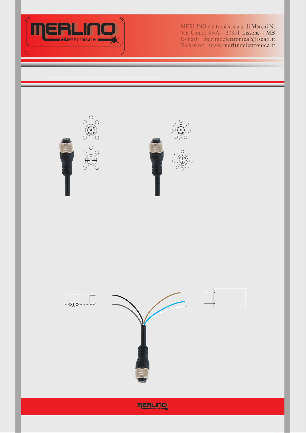
M12 - 8 poles male plug -M12 - 8 poli spina maschio
1) /Bianco
2)
3) /Verde
4) /Giallo
White
Green
Yellow
Brown/Marrone
= OUT1
= OUT2
= BLANKING R/F
= EDM/STR-RSTR
5) /Grigio
6) /Rosa
7) /Blu
8) /Rosso
Grey
Pink
Blue
Red
= Mute1
= Mute2
= + 24V
= GND
Connect Shield to GND - Collegare lo Schermo a GND
If the functions E.D.M. and START/RESTART are not used connect the conductor 4 to GND
Se le funzioni E.D.M. e START/RESTART non vengono utilizzate collegare il conduttore 4 a GND
12
3
4
5
6
7
8
M12 - 8 poles male plug -M12 - 8 poli spina maschio
1) /Bianco
2)
3) /Verde
4) /Giallo
White
Green
Yellow
Brown/Marrone
= SW1
= SW2
= BLANKING R/F
= EDM/STR-RSTR
5) /Grigio
6) /Rosa
7) /Blu
8) /Rosso
Grey
Pink
Blue
Red
= SW1
= SW2
= + 24V
= GND
Connect Shield to GND - Collegare lo Schermo a GND
If the functions E.D.M. and START/RESTART are not used connect the conductor 4 to GND
Se le funzioni E.D.M. e START/RESTART non vengono utilizzate collegare il conduttore 4 a GND
CF
R
CF
R
Pag. 9
DESIGN AND MANUFACTURE
OF ELECTRONIC EQUIPMENT
MERLINO elettronica s.a.s. di Meroni N.
Via Como, 33/A - 20851 Lissone - MB
E-mail: [email protected]
Web-site: www.merlinoelettronica.it
On both Transmitter (TX) and Receiver (RX) there is a label showing all the technical data
typical of the device according to the Machinery Directive 2006/42/EEC Annex l° § 1.7.3
concerning safety components.
Following with reference to a specific model of active optoelectronic protective device with
visible light laser emission called “RED-RL” there is an example of rating plate
units
A second label, located on the aluminium housing, shows on how to carry out electrical
connections useful for a correct use of the device. It identified all the conductors with reference
to their colouring and to the corresponding function.
Label located on the
housing of the “TX”
section. The output
connector for the
electric connections
is a standard type
M 1 2 - 5 p o l e
Label located on the
housing of the “RX”
Type 2 section. The
output connector for
electric connections
is a standard type
M12 - 8pole
Label located on the
housing of the “RX”
Type 4 section. The
output connector for
electric connections
is a standard type
M12 - 8pole
Label located on the
housing of the "TX"
section. It shows the
features of the light
emitted and alert the
user not to look directly
the outgoing Laser beam
Label located on the
frontal head of the
“TX” section. It shows
the references for a
correct optic alignment
and the hole of the
outgoing Laser beam
Label located on the
frontal head of the
“RX” section. It shows
the references for a
correct optic alignment
and the four ingoing
holes to the sensors
Laser spot for a
perfect alignment
RX
2017Anno:
MISU-RED-RL-UK-1.0
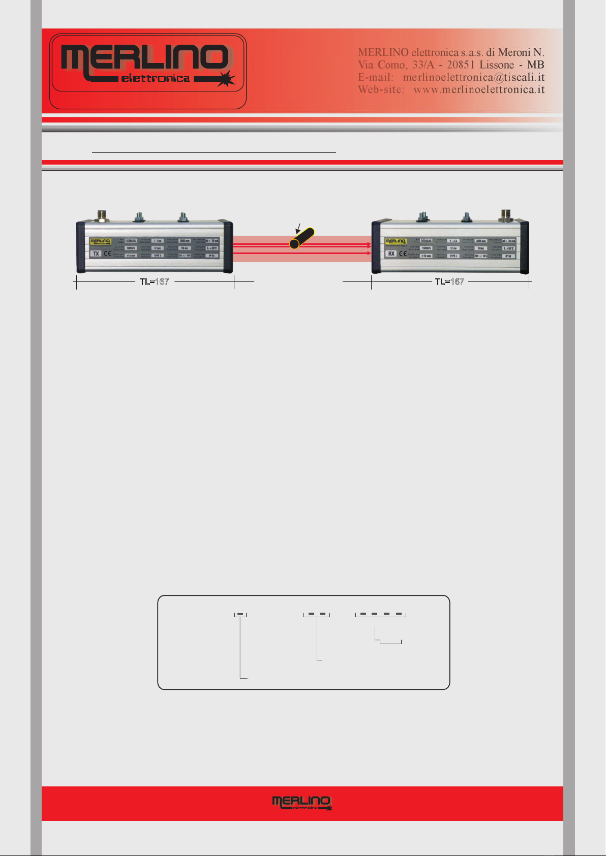
DETERMINING THE SAFE DISTANCE
10
Fig.11
Fig.10 TX
TL=167
RED-RL
TL=167
RX
Test Piece to check the integrity
of the detection capability
WD = up to 6m
MERLINO elettronica s.a.s. di Meroni N.
Via Como, 33/A - 20851 Lissone - MB
Web-site: www.merlinoelettronica.it
Pag. 10
DESIGN AND MANUFACTURE
OF ELECTRONIC EQUIPMENT
MERLINO elettronica s.a.s. di Meroni N.
Via Como, 33/A - 20851 Lissone - MB
E-mail: [email protected]
Web-site: www.merlinoelettronica.it
To ensure the device fulfils its accident prevention functions correctly, it must be installed at a
safe distance from the point actually dangerous for the operator of the machine in such a way as
to stop the dangerous movement before that point is actually reached.
The procedure for calculating this distance is established in the harmonised European standard
which gives a number of formulas using parameters dependent on various
factors discussed below (for more detail see the standard itself).
For information only, a number of examples to calculate the installation distance from the danger
point for vertically-installed light curtains with a detection capability of no more than 40 mm are
given below:
is the safe distance to be respected when installing the device
is a constant establishing the speed at which the operator approaches the danger point,
established at 2 meters per second
is the time in milliseconds deriving from the sum of the time t1 taken by the machine to stop
its dangerous movement after an ALT command and the time t2 taken by the light curtain to
open the OSSDs after an obstacle has been introduced into the protected area.
is the detection capability of the light curtain in millimetres
UNI EN13857,
-
-
(if S>500mm then reduce K=1,6 mt/sec)
-
-
S
K
T
d
where T = t1 + t2 while C = 8 x (d - 14)S=KxT+C
All models of the "RED-RL" active optoelectronic at Laser emission are calibrated during fac-
tory testing according to the specified by the customer in the last part of the
order code. Should it be necessary to modify this distance at a later date, you should contact
the manufacturer who will modify the calibration for the new working distance. Alternatively,
contact the factory telephonically for instructions on how to proceed.
working distance
REFERENCE CODE FOR ORDERING
SAFETY CATEGORY ( )2 OR 4
WORKING DISTANCE
(mm)
HIGH RANGE (HR)
RED -RL / /
MISU-RED-RL-UK-1.0
11 TECHNICAL CHARACTERISTICS
MERLINO elettronica s.a.s. di Meroni N.
Via Como, 33/A - 20851 Lissone - MB
Web-site: www.merlinoelettronica.it
Pag. 11
DESIGN AND MANUFACTURE
OF ELECTRONIC EQUIPMENT
MERLINO elettronica s.a.s. di Meroni N.
Via Como, 33/A - 20851 Lissone - MB
E-mail: [email protected]
Web-site: www.merlinoelettronica.it
PROTECTED HEIGHT (PH) 12mm
DETECTION CAPABILITY (DC) >14mm
WORKING RANGE
RESPONSE TIME 8msec
TX INDICATOR
OSSDs TYPES
PROTECTION FEATURES POLARITY INVERSION
SUPPLY VOLTAGE 24Vdc 10% 12Vdc on request±
CURRENT CONSUMPTION TX 70mA RX 50mA
WORKING TEMPERATURE 0 to + 50°C
UMIDITY 25 85%÷
FASTENING MEANS 4 x M5 THREADED STUDS
PROTECTION DEGREE IP54
1 6 meters÷
RX INDICATOR RED LASER BEAM = ACTIVE EMISSION
RED=ALARMGREEN=ALERT YELLOW=BLOCK
ORANGE=BLANKING F/R
TOTAL LENGHT (TL) TX=167mm - RX=167mm
2 VOLTAGE SWITCHES 0,7A@ 40Vdc/acFREE
EMISSION RED LASER = 650 nm / P=1mW
OUTPUT CONNECTION
5 METERS CABLE LENGHT M12 CONNECTOR TX = 5 POLE - RX = 8 POLE
HOUSING ANODIZED ALUMINIUM - CROSS SECTION 53 x 103 mm
AVAILABLE FUNCTIONS E D MXTERNAL EVICE ONITOR - START/RESTART INTERLOCK - BLANKING
PROTECTED HEIGHT (PH) 12mm
DETECTION CAPABILITY (DC) >14mm
WORKING RANGE
RESPONSE TIME 8msec
TX INDICATOR
OSSDs TYPES
PROTECTION FEATURES POLARITY INVERSION - OUTPUT SHORT CIRCUIT - CURRENT THRESHOLD
SUPPLY VOLTAGE 24Vdc 10% 12Vdc on request±
CURRENT CONSUMPTION TX 70mA RX 50mA
WORKING TEMPERATURE 0 to + 50°C
UMIDITY 25 85%÷
FASTENING MEANS 4 x M5 THREADED STUDS
PROTECTION DEGREE IP54
1 6 meters÷
RX INDICATOR RED LASER BEAM = ACTIVE EMISSION
RED=ALARMGREEN=ALERT YELLOW=BLOCK
BLK. RED= MUTING ORANGE=BLANKING F/R
TOTAL LENGHT (TH) TX=167mm - RX=167mm
2 PNP OPEN COLLECTORS 0,7A@ 40Vdc/ac
MAX. LOAD CAPACITY 0,1 uF
EMISSION RED LASER = 650 nm / P=1mW
OUTPUT CONNECTION
5 METERS CABLE LENGHT M12 CONNECTOR TX = 5 POLE - RX = 8 POLE
HOUSING ANODIZED ALUMINIUM - CROSS SECTION 53 x 103 mm
AVAILABLE FUNCTIONS
E D MXTERNAL EVICE ONITOR - START/RESTART INTERLOCK - MUTING - BLANKING
RED2-RL
TYPE2 - SIL1 - SILCL1 - PLc
NUMBER OF BEAMS 4
RED4-RL
TIPO4 - SIL3 - SILCL3 - PLe
MISU-RED-RL-UK-1.0
ELECTRICAL CONNECTIONS - TX
12
3
2
1POWER SUPPLY
24Vdc +/- 10%
BROWN
BLUE
BLACK
WHITE
GREY
5
4
TEST INPUT
NORMALLY CLOSED
CONTACT
Jumper
If the function TEST is not used, short
circuit the conductors 4-5 and connect
them to the “0V” of power supply blue (3) 5m standard
cable length
TX RED-RL
5 conductors cable
5 CONDUCTORS M12
FEMALE CONNECTOR
Fig.14
+24V
0V
RXTX
5
12
34
12
3
4
5
6
7
8
1
2
3
4
5
6
7
8
1) Brown
2) White
3) Blue
4) Black
5) Grey
= + 24V
=
= GND
= Test
= Test
GND
1) White
2) Brown
3) Green
4) Yellow
5) Grey
6) Pink
7) Blue
8) Red
Shield
= OSSD1................. SW1
= OSSD2 SW1
= BLANKING
= EDM/STR-RSTR
= MUTE1 SW2
= MUTE2 SW2
= + 24V
= GND
................
.................
.................
= GND
RED2-RL
1 2
3
5
4
Male plug
Female socket Female socket
Male plug
If the function TEST is not used, short
circuit the conductors 4-5 and connect
them to the “0V” of power supply blue (3)
If the functions E.D.M. and START-RESTART
are not used , connect the conductor
yellow (4) to the “0V” of the power supply
red/shield (8)
Fig.12 Fig.13
MERLINO elettronica s.a.s. di Meroni N.
Via Como, 33/A - 20851 Lissone - MB
Web-site: www.merlinoelettronica.it
Pag. 12
DESIGN AND MANUFACTURE
OF ELECTRONIC EQUIPMENT
MERLINO elettronica s.a.s. di Meroni N.
Via Como, 33/A - 20851 Lissone - MB
E-mail: [email protected]
Web-site: www.merlinoelettronica.it
5 CONDUCTORS M12
FEMALE CONNECTOR
8 CONDUCTORS M12
FEMALE CONNECTOR
MISU-RED-RL-UK-1.0

RX RED4-RL
8 conductors shielded cable
5
6
BROWN
WHITE
PINK
YELLOW
GREY
GREEN
D1
2
1
3
4
D2
E D Mxternal evice onitor
K2
I =max 0,7A
K1
OSSD1
MUTE1
Control devices of the function.
:when activated, temporarely, they
neutralize the light-curtain protective action.
MUTING
WARNING
OSSD2
MUTE2
5m standard
cable length
8 CONDUCTORS M12
FEMALE CONNECTOR
F1F2
Fig.16
P.N. : the E.D.M. function works
only if loads K1, K2, … Kn are
with forced interlocked contacts
operation. E.D.M. must be used to
reach the safety caegory declared.
I =max 0,7A
INTERLOCK
PUSH-BUTTON
START/RESTART
F1=F2= fuses of a higher value
than the current sinking
into the load (suggested)
D1=D2= rectifier diodes to suppress
“spikes” generated by t he an
inductive load that reduced
life of the output switches of
the light-curtain (recommended)
+24V POWER SUPPLY
24Vdc +/- 10%
SCR
SCR = extra-voltages discharger to
suppress possible high energy
discharge (recommended)
NC SWITCH
K1
NC SWITCH
K2
NC SWITCH
Kn
0V
BLUE
SHIELD
RED
7
8
{
RX RED2-RL
D1
D2
K1
K2
8 conductors shielded cable
5
6
BROWN
WHITE
PINK
YELLOW
GREY
GREEN
2
1
SW1
SW2
SW1
SW2
Imax = 0,7A
Imax = 0,7A
Vmax = 40Vdc/ac
Vmax = 40Vdc/ac
5m standard
cable length
F1
F2
F1=F2= fuses of a higher value
than the current sinking
into the load (suggested)
Fig.15
D1=D2= rectifier diodes to suppress
“spike” generated by the an
inductive load that reduced
life of the output switches of
the light-curtain (recommended)
8 CONDUCTORS M12
FEMALE CONNECTOR
SCR = extra-voltages discharger to
suppress possible high energy
discharge (recommended)
3
4
E D Mxternal evice onitor
If the functions E.D.M. and START-RESTART
are not used, connect the conductor
(4) to the “0V” of power supply
yellow
red/shield (8)
INTERLOCK
PUSH-BUTTON
START/RESTART
NC SWITCH
K1
NC SWITCH
K2
NC SWITCH
Kn
+24V POWER SUPPLY
24Vdc +/- 10%
SCR
0V
P.N. : the E.D.M. function works
only if loads K1, K2, … Kn are
with forced interlocked contacts
operation. E.D.M. must be used to
reach the safety caegory declared.
7
8
BLUE
RED
SHIELD
{
ELECTRICAL CONNECTIONS - RX
12.1
MUTING :
MERLINO elettronica s.a.s. di Meroni N.
Via Como, 33/A - 20851 Lissone - MB
Web-site: www.merlinoelettronica.it
Pag. 13
DESIGN AND MANUFACTURE
OF ELECTRONIC EQUIPMENT
MERLINO elettronica s.a.s. di Meroni N.
Via Como, 33/A - 20851 Lissone - MB
E-mail: [email protected]
Web-site: www.merlinoelettronica.it
For the Laser guard model, the “Neutralization” or “Muting” function is also previded, that is the possibility of being able to suspend in temporary way
its own protecting function. That it means that when the two dedicated inputs are simultaneously activated (within a maximum time of 0,8 second) putting
separately in short-circuit the PINK and GRAY conductors to the “0V” of power supply (RED conductor and Shield), the Laser Guard surveillance action comes
temporarely neutralized, allowing that the Laser beam can be darkened without that the output signal switching devices (OSSDs) switch to the inactive OFF state. A
red color blinking signaler, situated on the top head of the “RX” section (Pag.8), shows the activation of the Muting function. In the event of the two dedicated muting
inputs are not simultaneously activated, or however with a time delay more than 0,8 second, the RED4-RL switches into the block state opening the output signal
switching devices (OSSDs) and signaling it as the “D” case of the diagnostic table of Pag 8. Make attention using this function as it could generate potentially
dangerous situations. Adopt a visual and/or acoustic additional external signaler to indicate in unequivocal way the inactivity state of the Barrier to activated Muting.
“RED4-RL”
: disconnect the
green cable (3) from the
"0V" of the power supply (8)
to exclude Front and Rear
sensors of the device
BLANKING
BLANKING
BLANKING: disconnect the
green cable (3) from the
"0V" of the power supply (8)
to exclude Front and Rear
sensors of the device
BLANKING
EDM/STR-RSTR
EDM/STR-RSTR
If the functions E.D.M. and START-RESTART
are not used, connect the conductor
(4) to the “0V” of power supply
yellow
red/shield (8)
MISU-RED-RL-UK-1.0

MECHANICAL DATA
13
INTER-AXIS FIXING HOLES
Fig.17
RED-RL - TX
RED-RL - RX
Fig.18
Fig.19
MERLINO elettronica s.a.s. di Meroni N.
Via Como, 33/A - 20851 Lissone - MB
Web-site: www.merlinoelettronica.it
167
56
56
53
53
30
51
30
5066
30
20
167
51 50 66 20
50
4 x M5
45
4 x M5
45
50
Pag. 14
DESIGN AND MANUFACTURE
OF ELECTRONIC EQUIPMENT
MERLINO elettronica s.a.s. di Meroni N.
Via Como, 33/A - 20851 Lissone - MB
E-mail: [email protected]
Web-site: www.merlinoelettronica.it
MISU-RED-RL-UK-1.0
MAINTENANCE AND CONTROLS
14
MERLINO elettronica s.a.s. di Meroni N.
Via Como, 33/A - 20851 Lissone - MB
Web-site: www.merlinoelettronica.it
Pag. 15
DESIGN AND MANUFACTURE
OF ELECTRONIC EQUIPMENT
MERLINO elettronica s.a.s. di Meroni N.
Via Como, 33/A - 20851 Lissone - MB
E-mail: [email protected]
Web-site: www.merlinoelettronica.it
The Transmitter and Receiver units do not require particular maintenance. However, the frontal
heads of the two sections protective of the optics, with the holes for exit and entrance of the laser
light beam, should be cleaned daily to remove large quantities of dust.
Avoid rubbing the screens with abrasive cloths as rubbing causes static electricity and attracts
dust. To clean, use alcohol. Avoid plastic solvents.
When the device is used for the first time, to guarantee safe conditions, the correct setting of the
functions must be controlled. When using the device for the first time, operation of the device in
the particular application must first be verified. This must be done by specialist personnel. Acci-
dent prevention legislation specifies that this control should be performed daily.
Before beginning any form of work, it is good practice to verify that:
with the machine stationary and power to the laser guard on (no obstacle in the protected
area), the green indicator is lit.
with the machine stationary and power to the on in the presence of an obsta
cle in the protected area, the red indicator is lit.
moving parts are not accessible to personnel. Any extraordinary maintenance must
therefore be carried out under the strict supervision of the safety manager. All accesses
not pro tected by electro sensitive protective devices must be equipped with fixed material
barriers or other.
A sheet indicating the daily checks must be compiled by the operator of the machine and must
be clearly visible near the workstation.
DAILYCONTROLSANDPERIODICALTESTS
RUN
ALT laser guard
with the machine running, introduction of the test piece at any point in the protected area
switches the green indicator to the red indicator, shutting down the machine within the
specified time.
The "RED-RL" active optoelectronic visible light laser emission intangible guard consists of the
following elements, provided on request as spare parts:
M12 - 5 poles output connector for TX with 5 m long cable...................
M12 - 8 poles output connector for RX with 5 m long cable................
Manual with duplicate of the “ DECLARATION OF CONFORMITY
ALT
MATERIALSUPPLIEDASSPAREPARTS
a)
b)
d)
c)
- ...... CON-M12-5P-5M
- ......... CON-M12-8P-5M
- ”........... MISU-RED
- Cylinder for testing the integrity of the detection capability ........................... TEST-PIECE
Description Code
MISU-RED-RL-UK-1.0
This manual suits for next models
2
Table of contents
Other Merlino Safety Equipment manuals


