FingerTec i-Neighbour Siren Kit Assembly instructions

Siren Kit
Installer Guide
(SK-911)

2
Siren Kit
Get the i-Neighbour Siren Kit to enhance your residential secu-
rity system fuss-free! The Siren Kit has a Raspberry Pi controller, an
I/O board, and a power supply encased in a compact casing
for an easy installation at the guardhouse. The Siren Kit connects
effortlessly to your i-Neighbour residential management system
account at all times through an active Internet connection and
it is designed to link to LED display panel and alarm siren with
strobe light that are weatherproof and suitable for outdoor en-
vironment.
In any episode where a resident pushes the Panic Button from
the i-Neighbour app during emergencies, the i-Neighbour Siren
Kit will display the resident’s unit number on the LED panel, and
set off the siren to alert the on-duty security officers for rescue.
Simple, effective and affordable, i-Neighbour Siren Kit is an ex-
tra security you need to strenghten your security during emer-
gencies.
Extra Security for Emergency
(SK-911)

3
UNDERSTANDING THE SK-911 SIREN KIT
UNDERSTANDING THE TECHNICAL SPECIFICATIONS
HARDWARE •Surfacenishing
• Dimension, mm
POWER • Power input
SUPPLY • Backup power
SIREN KIT I/O • Input
• Output
RASPBERRY PI • Processor
CONTROLLER • WiFi
• Bluetooth
• USB
• GPIO
• HDMI
• Power input
• Supported Accessories
Acrylonitrile Butadiene Styrene (ABS)
212 x 49 x 114
AC 110 ~ 240V (Universal Input)
UPS or 12VDC rechargeable battery
4 x Digital Input
12VDC 1A strobe sight, 12VDC 3A siren,
5A Dry contact free relay
1.2 GHz 64bit Broadcom BCM2837, 1GB RAM
BCM43438 - Single-Chip IEEE 802.
11 b/g/n MAC/Baseband/Radio
BCM43438 - Bluetooth Low Energy
4x USB 2.0
40 pin
Full size HD output
5.1 VDC 2.5A
Alarm Siren and Strobe Light
Ampliesalertduringemergencies.
HDMI Output
Provides the option to display the residents’ addresses on other
devices such as computer monitor instead of LED panel.
Action Buttons
Allows 3-button pack for security guard to trigger and to stop the
siren kit manually, as well as acknowledge the receipt of emer-
gency report.
Resident presses
panic button from
i-Neighbour
mobile app
i-Neighbour
Cloud Base
VMS System Wireless router
connects to active
Internet connection
AC110/240V
Power Input
i-Neighbour
Alarm Siren &
Strobe Light
Action Buttons
i-Neighbour LED Display Panel

4
12
7 8
9
10
654
3
UNDERSTANDING THE DESIGN
Power supply/power input module
1Connect this point to a AC 110 ~ 240V power source in order to
generate a 12VDC 3A power output.
2By default, the -V and +V cables are connected to the inner parts
of the I/O board. .
Note: Please do not remove or change these cables
Power output/alarm module
3Connect these cables to a 12VDC 3A (maximum output ampere)
alarm siren. Alarm siren will be triggered when residents push the
Panic Button in i-Neighbour App. Skip this step if you will not be using
the alarm siren.
Note: If you are using an alarm device that contains both siren and strobe
light, connect it to port (1) – Siren.
4Ignore these ports as they are meant for manufacturer use only.

5
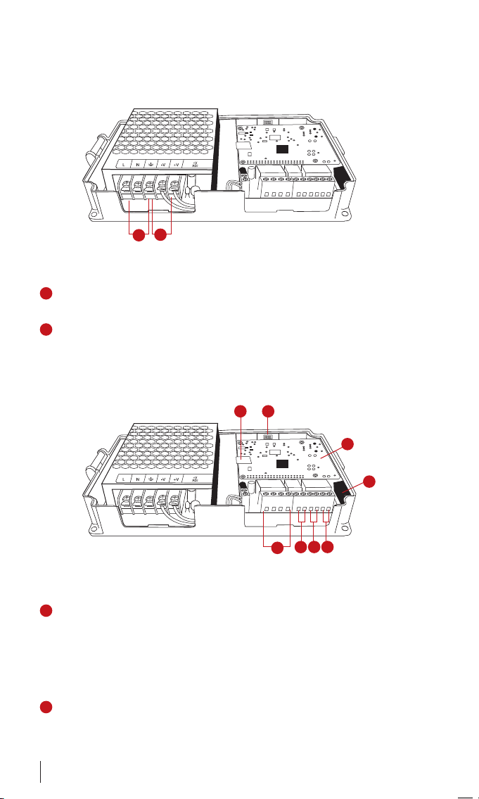
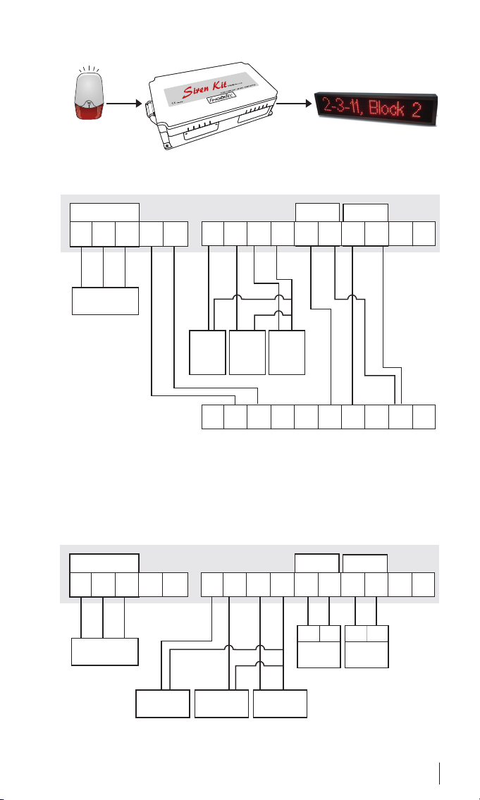
5These four ports are connected to three different buttons which
control the SK-911 Siren Kit
• Acknowledge Alarm Button
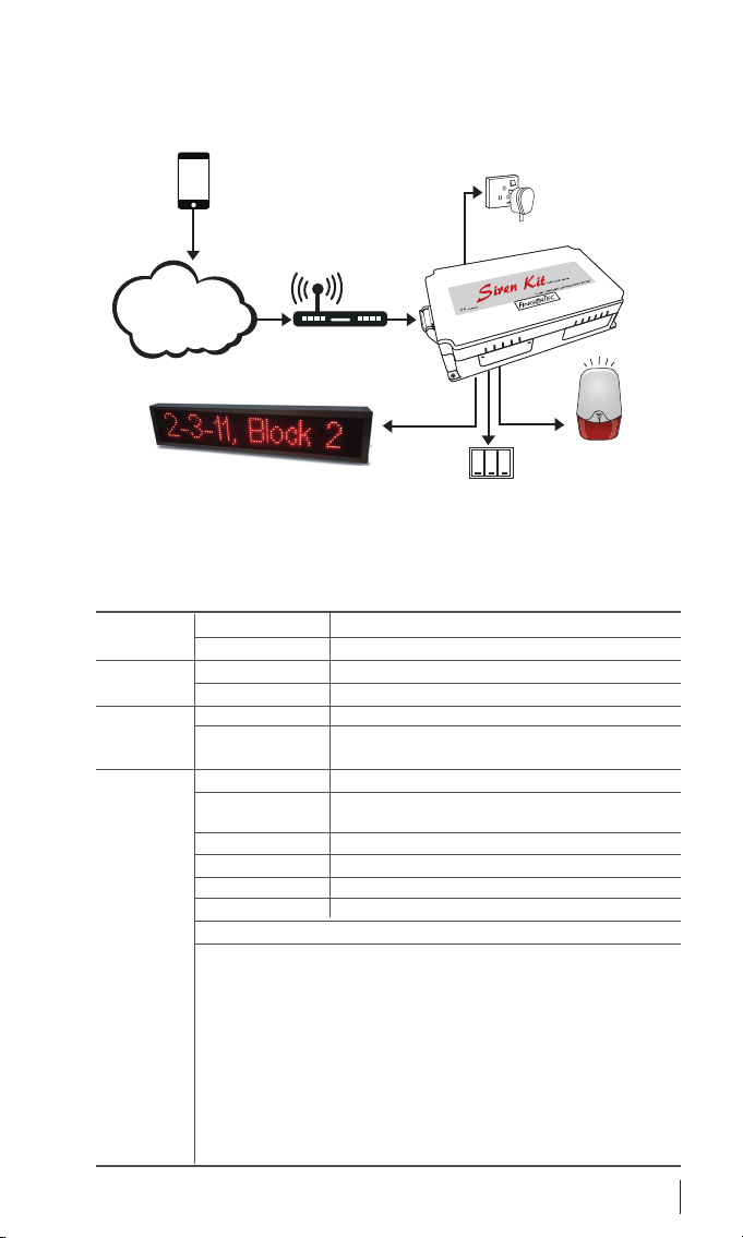
When a resident triggers the Panic Button through i-Neighbour
Mobile App, the SK-911 will activate the siren and strobe light
in addition to instantly displaying the unit no. of the resident on
the LED display panel. Another push on this button will stop the
siren and strobe light. However, the unit no. will still be displayed
on the LED display panel until the Panic Button S.O.S request has
been cancelled
• Panic Alarm Button
During emergency at the guard house, the security guard can
also push this button to trigger the siren alarm and strobe light. To
cancel, press Stop Alarm Button.
• Stop Alarm Button
Press to turn off the alarm siren and strobe light that were acti-
vated by Panic Alarm Button
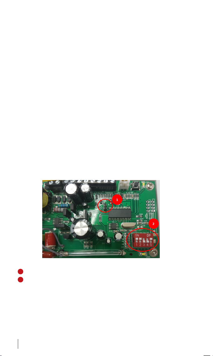
6This is an SD card lot to slot in the pre-programmed card from i-
Neighbour. The Raspberry PI controller executes commands based
on contents of this card. Caution: Do not remove or edit the con-
tents of this SD card to prevent permanent system failure.
7This is an SD card slot for the pre-programmed card provided by i-
Neighbour. The Raspberry PI controller executes commands based
on the contents within this card. Caution: Do not remove or edit
the contents of this SD card to prevent permanent system failure.
8This is a HDMI output for connecting to a computer LCD during the
initial setup of SK-911 or troubleshooting process.
9These are the USB input ports to plug in keyboard, mouse and USB
flash disk for initial setup of SK-911 or troubleshooting and repair
purposes. Caution: Do not plug in any USB flash disk or cables into
these ports that could cause permanent system failure.
10 This is a customized serial port designed for the external LED display
panel to transmit data for display only and not to power up the LED
panel.

6
DETAILS OF WIRING
The i-Neighbour Siren Kit SK-911 has to be connected to a power
source with AC 110 ~ 240V. The integrated switching power supply will
automatically convert the input power to DC12V 5A to be distributed
to the system.
To avoid from damaging the SK-911, we recommend installer to do
the wiring for siren, strobe light, LED display panel, buttons and HDMI-
output devices (computer LCD, if necessary) before making any con-
nections to the AC power.
It is strongly recommended to power up the entire system once you
have done all the steps
Caution: Do not attempt to modify or repair any components in the SK-911 or the
warranty will be voided immediately.
WIRING DIAGRAM
To connect to i-Neighbour SS-911
Step 1 • Configure the i-Neighbour SS-911.
1Remove the connector from jumper.
2Set the DIP switch as shown in picture.

7
L N G -V +V IN1 IN2 IN3 0V + - + - COM NO
Siren Strobe
AC110 - 240V
power input
Power Input
L N G -V +V IN1 IN2 IN3 0V + - + - COM NO
Siren Strobe
AC110 - 240V
power input
Power Input
Acknowledge
alarm button
Panic alarm
button
Stop alarm
button
+ -+ -
DC 12V 1A
Strobe light
DC 12V 3A
Siren unit
i-Neighbour LED Display Panel
i-Neighbour
Alarm Siren &
Strobe Light
+ GND 12V+ GND S- S+ L+ L- GND
Acknowl-
edge
alarm
button
Panic
alarm
button
Stop
alarm
button
From i-Neighbour SS-922
To connect to conventional siren or strobe light

8
SYSTEM CONFIGURATION
Step 1 • Connect SK-911 to the Internet
You will need to connect the following items to the HDMI output and
USB ports located at the SK-911 for the initial setup:
1. Keyboard (USB port)
2. Mouse (USB port)
3. Computer LCD screen (HDMI output)
At the start up screen, connect the SK-911 to the nearby network with
Internet accessibility.
Follow the steps below:
The Disconnection icon will appears on the lower right corner. Click on
the Disconnection icon to connect.
SelectSSID(WiID)andllinthepasswordtoconnect.Tousemobile
data network, click on the GSM tab and select a Network Carrier.

9
The connection status icon will appears at the lower right corner indi-
cating that a connection has been established.
Step 2 • Configure the display of SK-911
Clickonthesettingsiconandll
in the default password (123456)
to start conguring. You can
change the password in the Pro-
letablater,followingtheinstruc-
tions below.
At the Settings tab, you can set:
• Brightness of LED display
• Text scrolling speed
• Display during standby mode,
which can be a message or
date & time.
AttheProletab,youcan:
• Find the serial number of
i-Neighbour SK-911. You will
need this serial number to add
the siren kit into i-Neighbour
system, which will be ex-
plained in Step 3.
• Change the password of the
siren kit. Default password is
123456.
Finally, remove the keyboard,
mouse and computer LCD from
SK-911.

10
Step 3 • Activate the SK-911 through an i-Neighbour account
By using a computer, tablet or smartphone,
visit https://www.i-neighbour.com/ login to the system admin’s account
and follow the steps below in order to add the SK-911 into your i-Neigh-
bour account:
1. Go to Settings > Siren Kit
2. Click Add
3. Insert a name for the SK-911 and its serial number. Refer to the SK-
911 box for the serial number.
4. Done! The SK-911 is now added into your account. Please make
sure that the SK-911 is connected to the Internet at ALL TIMES in
order for it to operate properly.
Repeat the steps above to install more than one SK-911 in your neigh-
bourhood.

© 2017 Timetec Computing Sdn Bhd. All rights reserved • 082017
This manual suits for next models
1
Table of contents
Other FingerTec Safety Equipment manuals