Micro Detectors LS2 Series User manual
M.D. Micro Detectors
Strada S. Caterina, 235
41122 Modena Italy
Tel. +39 059 420411
Fax +39 059 2539 3
www.microdetectors.com
LS2 SERIES
SAFETY LIGHT CURTAIN TYPE 2
LANGUAGE
Installation and Operation Manual
ENGLISH
M.D. Micro Detectors CAT8ELS1250901 1/34

M.D. Micro Detectors
Strada S. Caterina, 235
41122 Modena Italy
Tel. +39 059 420411
Fax +39 059 2539 3
www.microdetectors.com
LS2 SERIES
SAFETY LIGHT CURTAIN TYPE 2
LANGUAGE
Installation and Operation Manual
ENGLISH
M.D. Micro Detectors CAT8ELS1250901 2/34
CONTENTS
1.0 ABOUT THIS DOCUMENT ............................................................................................................. 3
1.1 Function of this document ................................................................................................................ 3
1.2 Symbols used in this document ......................................................................................................... 3
2.0 WITH REFERENCE TO SAFETY ....................................................................................................... 4
2.1 Skilled personnel ............................................................................................................................... 4
2.2 Fields of use of the device ................................................................................................................. 4
2.3 General safety instructions and measures of protection .................................................................. 5
2.4 Disposal.............................................................................................................................................. 5
3.0 DESCRIPTION OF THE PRODUCT ................................................................................................... 5
3.1 rief description ................................................................................................................................ 5
3.2 Coding system.................................................................................................................................... 6
3.3 Availability of models with IP65 + IP67 protection ........................................................................... 7
3.4 Availability of models with IP69K protection .................................................................................... 7
3.5 Possibility of interconnection of the available models ..................................................................... 8
4.0 INSTRUCTIONS FOR POSITIONING THE SAFETY LIGHT CURTAINS .................................................. 9
4.1 Respecting the safety distance .......................................................................................................... 9
4.2 How to calculate the safety distance S in conformity with EN ISO 13855 and EN ISO 13857 ........ 10
5.0 MINIMUM DISTANCE FROM REFLECTING SURFACES .................................................................. 13
5.1 How to calculate the minimum distance from reflective surfaces ................................................. 13
6.0 COMMISSIONING ...................................................................................................................... 14
6.1 Mechanical mounting ...................................................................................................................... 14
6.2 Alignment ........................................................................................................................................ 14
6.3 Electrical installation. ...................................................................................................................... 15
7.0 TECHNICAL SPECIFICATIONS. ..................................................................................................... 19
.0 PANEL AND DIAGNOSTICS INDICATIONS .................................................................................... 20
8.1 Symbols used to indicate the LED indicators modes ....................................................................... 20
8.2 Indications of the panels ................................................................................................................. 20
8.3 Interpretation of error codes .......................................................................................................... 21
9.0 LISTS OF AVAILABLE MODELS AND MAIN CHARACTERISTICS ....................................................... 22
10.0 MECHANICAL DIMENSIONS, BARRIERS AND STANDARD ACCESSORIES ....................................... 29
10.1 IP67 models ..................................................................................................................................... 29
10.2 IP69K models ................................................................................................................................... 31
11.0 LIST OF ACCESSORIES APPLICABLE TO THIS PRODUCT ................................................................. 32
12.0 CONTENT OF THE PACKAGE ....................................................................................................... 32
13.0 CHECKING THE SYSTEM ............................................................................................................. 33
13.1 Purpose of the checks...................................................................................................................... 33
13.2 Checks prior to commissioning ........................................................................................................ 33
13.3 Regularity of the checks by qualified personnel ............................................................................. 33
13.4 Regular checks on the effectiveness of the protection device........................................................ 33
14.0 CE DECLARATION OF CONFORMITY............................................................................................ 33
15.0 GUARANTEE .............................................................................................................................. 34
M.D. Micro Detectors
Strada S. Caterina, 235
41122 Modena Italy
Tel. +39 059 420411
Fax +39 059 2539 3
www.microdetectors.com
LS2 SERIES
SAFETY LIGHT CURTAIN TYPE 2
LANGUAGE
Installation and Operation Manual
ENGLISH
M.D. Micro Detectors CAT8ELS1250901 3/34
1.0 ABOUT THIS DOCUMENT
Please read t is document carefully before mounting, starting, using and servicing LS2 safety lig t curtains; it contains
detailed instructions t at must be followed wit care.
In addition, pay special attention to C apter 2 “With reference to safety”.
THIS DOCUMENT IS NOT IN ITS ORIGINAL LANGUAGE
1.1 Function of this document
T is document provides t e tec nical personnel of t e manufacturer of a mac ine or t e manager of t e mac ine wit
t e necessary instructions for safe mounting, electrical connection, starting and normal operation and maintenance of LS2
safety lig t curtains.
T e design and use of safety devices t at utilize LS2 safety lig t curtains require specific knowledge, but t is is not
entirely provided in t is document.
T e prescriptions of aut orities and of t e law must also be fundamentally respected for t e installation and during
normal operation of LS2 safety lig t curtains.
1.2 Symbols used in this document
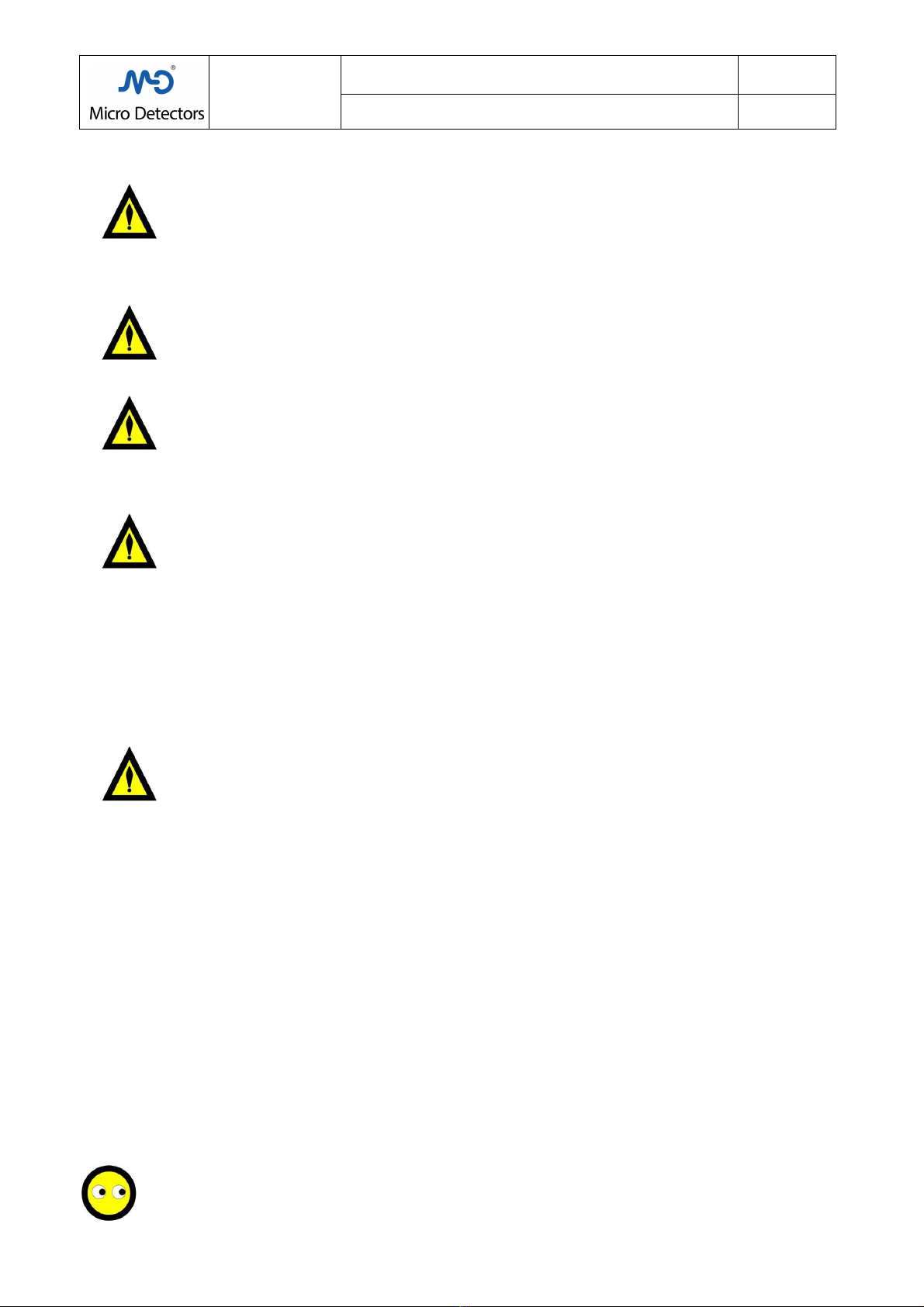
Warning to avoid danger!
A warning indicates real or potential azards.
Its task is to indicate procedures and be aviour t at can avoid accidents.
Read and follow t ese instructions carefully.
Indication
Indications t at can elp ac ieve better performance.
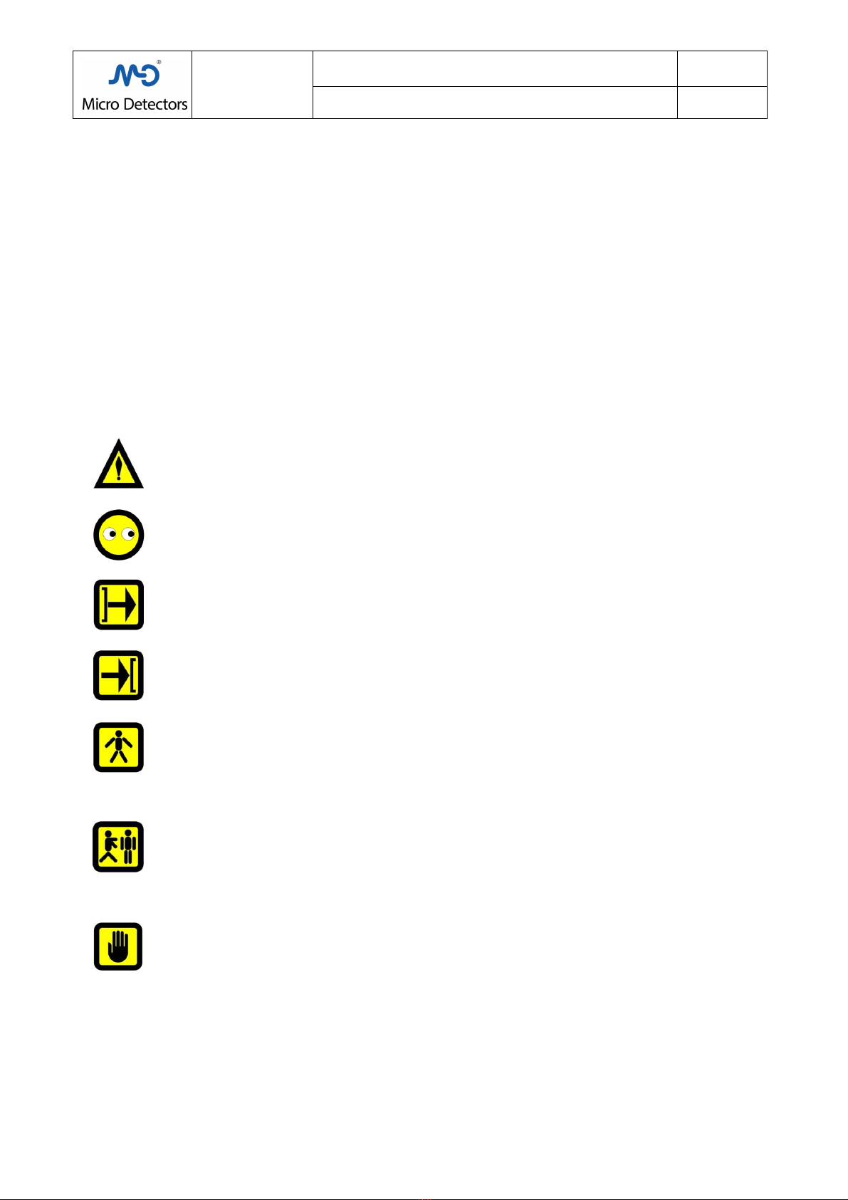
Emitter
symbol
T is symbol identifies devices t at ave t e function of an Emitter.
Receiver symbol
T is symbol identifies devices t at ave t e function of a Receiver.
Body detection
T is symbol marks devices designed to detect a body entering a protected area.
It refers to multi-beam safety lig t grids wit 2, 3 or 4 beams.
T ese safety lig t grids are usually cost-effective and feature a long range, t ey enable creating
protection for extensive areas and on more t an one side, using diverter mirrors.
T ese models are available in t e LS2 series.
Limb or presence detection
T is symbol marks devices designed to detect limbs entering a protected area or detect uman
presence in a protected area.
For presence detection, wit safety lig t curtains in a orizontal position, resolutions of between 50
and 116mm are to be used, t e eig t off t e ground is calculated in relation to t ese values.
For t is function t e LS2 series features models wit resolutions of 50 and 90mm.
Hand detection
T is symbol marks devices designed to detect a and entering a protected area.
It refers to safety lig t curtains wit a resolution less t an or equal to 30mm and 40mm; t ese
resolutions allow safety distances compatible wit s ort loading and unloading times and a low level of
operator fatigue.
M.D. Micro Detectors
Strada S. Caterina, 235
41122 Modena Italy
Tel. +39 059 420411
Fax +39 059 2539 3
www.microdetectors.com
LS2 SERIES
SAFETY LIGHT CURTAIN TYPE 2
LANGUAGE
Installation and Operation Manual
ENGLISH
M.D. Micro Detectors CAT8ELS1250901 4/34
2.0 WITH REFERENCE TO SAFETY
Warning!
T e level of protection of t e safety lig t curtain must be compatible wit t e dangerousness of t e
system to control, devices downstream from t e must be compatible wit t e safety lig t curtain itself
and wit t e required safety level.
- T e mac ine must be able to be controlled electrically.
- It must be possible to stop t e dangerous parts of t e mac ine wit an electric control ac ievable in a
definite time and if necessary verified directly.
Warning!
T e features of t e safety lig t curtains must be c osen according to t e size of t e access area to t e
dangerous zone, t e part of t e uman body subjected to t e danger, t e distance of t e point of
access from t e dangerous point, t e response time of t e safety lig t curtains , t e response time of
t e downstream devices and t e time for stopping t e dangerous movement.
Warning!
All t e remaining azardous conditions of t e mac ine must be verified and suitable equipment must be
used to neutralize t em.
It must not be possible to reac t e dangerous zone wit out going t roug t e protection surface
controlled by t e safety lig t curtains.
For an operator must not be possible to remain between t e surface of t e protection controlled by t e
barrier and t e danger zone wit out being detected.
Warning!
C eck t at t e environmental conditions are compatible wit t e features of t e safety lig t curtains .
C eck t e effect of reflective surfaces to t e side of t e pat of t e lig t beams, in general respect t e
indicated safety distances.
Consider t e effect of putting transparent panels or t e like in between t at can c ange t e beam angle
of t e safety lig t curtains .
Prevent t e safety lig t curtain's optical window from getting damaged or altered wit scratc es and
opacifications.
Do not expose t e Receiver to strong natural or artificial sources of lig t, including flas ing stroboscopic
sources.
Avoid exposing t e Receiver directly to t e projection of optical beams of ot er optical devices.
C eck t at t e ambient temperature does not exceed t e stated limits.
Consider t e effect of smoke, vapours, liquids and powders t at can alter t e transparency of t e air or
foul t e optical window.
Warning!
Periodically perform t e procedures for c ecking t e functionality of t e safety lig t curtain.
2.1 Skilled personnel
Only qualified personnel are aut orized to mount, start up, use and service t e
LS2
safety lig t curtain
.
A qualified person is one w o:
- as adequate tec nical training
- as been educated by t e person in c arge of Mac ine Safety on its use and t e current safety directives
- accesses t e operating instructions.
2.2 Fields of use of the device
T e LS2 safety lig t curtains are Type-2 electro-sensitive protection equipment (ESPE) in accordance wit
IEC 61496-1 and IEC 61496-2. T ey can be employed in safety applications up to Category 2 in conformity wit
EN ISO 13849, up to SIL CL 2 in conformity wit EN 62061 or up to PL d in conformity wit EN 13849.
T ey meet t e requirements of t e Mac inery Directive 2006/42/EC and are used to:
- protect t e area of access to dangerous points.
- detect uman presence in dangerous zones.
- protect t e accesses to dangerous zones.
Use to standard
LS2 safety lig t curtains
must be used only in accordance wit C apter 2.2 “Fields of use of t e device”. If t e
device is used for ot er purposes or if it is modified, even in t e p ase of mounting or installation, t is
invalidates all warranty rig ts wit M. D. Micro Detectors.

M.D. Micro Detectors
Strada S. Caterina, 235
41122 Modena Italy
Tel. +39 059 420411
Fax +39 059 2539 3
www.microdetectors.com
LS2 SERIES
SAFETY LIGHT CURTAIN TYPE 2
LANGUAGE
Installation and Operation Manual
ENGLISH
M.D. Micro Detectors CAT8ELS1250901 5/34
2.3 General safety instructions and measures of protection
Safety instructions!
To ensure LS2 safety lig t curtain
s are used to standard and in a safe manner it is necessary to observe t e following
points:
• For t e installation and use of t e LS2 safety lig t curtain
as for commissioning it and t e repeated tec nical tests,
national and international regulations apply, particularly:
– Mac inery directive 2006/42/EC
– t e Directive on work equipment operators 2009/104/EC
– t e accident prevention prescriptions and safety rules
– ot er important safety prescriptions.
• T e manufacturers and operators of t e mac ine on w ic t e LS2 safety lig t curtain
is used must, in agreement wit
t e relevant aut ority and under t eir own responsibility, apply all t e current safety rules and prescriptions and are also
in c arge of t eir observance.
• It is absolutely necessary to observe t e guidelines on c ecking
t ese operating instructions (see c apter 6
“Commissioning”).
• T e c ecks must be carried out by qualified persons, t at is by aut orized and specially appointed persons, and t ey
must be documented so as to be compre ensible at any moment.
• T e operating instructions contained in t is manual must be set at t e disposal of t e operator of t e mac ine used
wit LS2 s.
T e mac ine operator must be educated by qualified personnel and urged to read t e operating instructions.
2.4 Disposal
Dispose o
f unusable or unrepairable devices always in observance of current national prescriptions on t e subject of
waste disposal.
3.0 DESCRIPTION OF THE PRODUCT
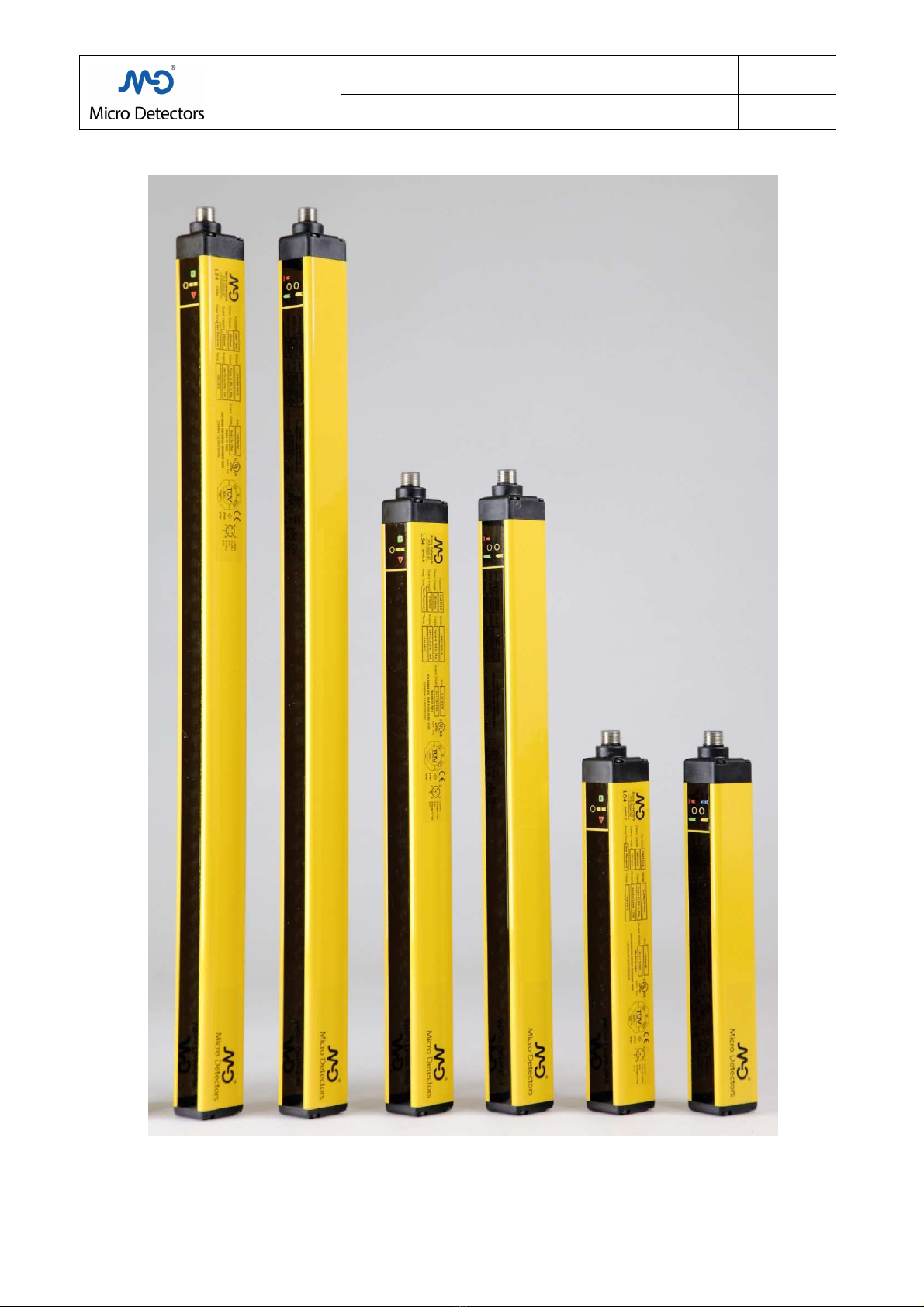
3.1 Brief description
T e LS2 series curtains are multiple lig t beam safety devices, built in compliance wit t e IEC 61496-1 and 2
standards, are Type 2 and t erefore applicable for t e protection of t e operators of systems or dangerous mac ines.
According to t e requirements of t e EN 61496-1 standard, a Type-2 safety lig t curtain must be able to carry out
periodical testing on its internal circuits to detect t e presence of any dangerous faults.
LS2 safety lig t curtains ave a slim profile of 28x30mm, t e distance of 28mm refers to t e front side, t ey ave a
rear groove for fastening, t ey are extremely reliable devices, t e Receivers provide two protected static safety PNP
outputs, so t ey are not subject to output contact wear or affected by strong vibration, t ey are able to detect
internal faults, control external contacts and, in t e event of a fault, ensure safe be aviour in any case. Wit a free
area t e level of t e two outputs is enabled to be ig (status ON, outgoing current), wit an occupied area or in case
of fault t e level is low (status OFF).
T e Emitters ave a Test input, t at can be used if it is necessary to control t e devices downstream from t e
Receiver.
T ere are models wit different resolutions (smaller diameter of t e detectable object) dedicated to certain detection of
ands, limbs and body; t e different resolution for models of t e same type enables c oosing different safety
distances.
Safety lig t curtains are available wit resolutions of 30, 40, 50, 90 mm, eig ts from 160 to 1510mm, maximum
ranges of 3, 4, 10, 12m. Multi-beam safety lig t greed are available wit 2, 3, 4 beams dedicated to access control.
T e Base and standard models can be used individually, t e Master, Slave and Final slave models can be used in
a c ain of two or t ree elements, also wit different types of optics; t is enables creating complex applications in a
simple cost-effective manner, for ig ly integrated protected zones even wit different resolution or range
requirements.
T e Base models ave only t e automatic restart function wit out controlling t e external contacts (EDM).
On t e standard and Master models it is possible to combine all t e functions by wiring as preferred: external
contact control (EDM), automatic starting, manual starting.
All t e models use M12 connectors with 5 or 8 poles, for t e supply/output cables and t e interconnection cables
in a c ain no s ielding is required, t e output cable can reac lengt s of 100m, t e interconnection cable 50m, t ese
features also allow great operational flexibility.
T e required operational voltage is 24V
DC
±20%, t e absorbed power is moderate, at most 3W per pair; t e
maximum output current is 400mA, suited to drive even power contactors directly; t e restart interlock and EDM
function, present on t e standard and Master models, enable making versatile and integrated protection systems.
Normally, t e degree of protection of t e ousing is IP65+IP6 , suitable also for dusty environments or compatible
wit p enomena of condensation, except for t e front surface t at as strict optical requirements.
Models are available wit IP69K protection t at can be subjected to was ing wit jets of ot water up to 80°C and
pressure up to 80 bar; wit t is level of protection models are also available wit an integrated t ermal auto-control
system t at moreover enables working at temperatures as low as -25°C and avoiding condensation on t e optics.

M.D. Micro Detectors
Strada S. Caterina, 235
41122 Modena Italy
Tel. +39 059 420411
Fax +39 059 2539 3
www.microdetectors.com
LS2 SERIES
SAFETY LIGHT CURTAIN TYPE 2
LANGUAGE
Installation and Operation Manual
ENGLISH
M.D. Micro Detectors CAT8ELS1250901 6/34
3.2 Coding system
Tab.:1 gives t e meaning of t e codes of t e available models.
T e models are supplied in kit form composed of a pair (Emitter/Receiver), t e single elements are available only to
make up for a return.
For an overview of t e main features of t e models ready for delivery or available on request, see Tab.:2 and 3 in t is
c apter.
For a complete and detailed list of t e actually coded models and t eir related features, see C apter 9.
Directly contact M. D. Micro Detectors for any explanation.
LS2 SERIES CONSTRUCTION OF MODEL CODES
POSITION CODE DESCRIPTION
1 LS2 Type-2 safety lig t curtains in ousing of cross-section 28x30mm
2
R Receiver (single element only available for t e replacement of return goods)
E Emitter (single element only available for t e replacement of return goods)
ER Emitter/Receiver pair
3 / Separator
4
30, 40 Lig t curtain, resolution in mm; and protection
50, 90 Lig t curtain, resolution in mm; limb protection
0A, 0B, 0C
Multiple beams
lig t grid
, number of beams 2, 3, 4; body protection
Corresponding centre distance of t e beams 500, 400, 300mm
5 - Separator
6
015 to 150
Nominal eig t of controlled area in cm for
lig t curtain
models:
015, 030, 045, 060, 075, 090, 105, 120, 135, 150
050, 080, 090 Centre distance of t e end beams in cm for lig t grid models
Single element wit selectable functions (Standard)
B
Single element wit only Base functions
(Automatic restarting only)
(For t e Emitters t e Standard and Base models are identical, t e code of t e
pair is defined by t e Receiver)
M Master element wit selectable functions
S Intermediate Slave element
F Final Slave element
8
IP65 + IP67 Operating Temp. -10…55°C
K
Models in transparent cylindrical ousing, IP69K, suitable for applications in t e
food industry.
Resistance to was ing wit water at 100 bar, 80 ° C
Housing in PMMA, caps in POM C wit silicone seals.
Brackets in stainless steel AISI 316L.
Operating temperature -10 ... 55 ° C.
H
Models in transparent cylindrical casing, IP69K protection, t ermostated, suitable
for applications in t e food industry.
Resistance to was ing wit water at 100 bar, 80 ° C
Housing in PMMA, POM C caps and silicone seals.
Brackets in stainless steel AISI 316L.
Operating temperature -10 ... 55 ° C.
Tab.:1; Chap.:3
M.D. Micro Detectors
Strada S. Caterina, 235
41122 Modena Italy
Tel. +39 059 420411
Fax +39 059 2539 3
www.microdetectors.com
LS2 SERIES
SAFETY LIGHT CURTAIN TYPE 2
LANGUAGE
Installation and Operation Manual
ENGLISH
M.D. Micro Detectors CAT8ELS1250901 7/34
3.3 Availability of models with IP65 + IP6 protection
Tab: 2 and 3 give t e actually available models wit reference to t e optical parameters. T e selection between t e two
“Low” and “Hig ” ranges is performed via t e cables in t e Emitter. Models wit an extended range are not available,
w ic are instead available in t e LS4 series.
See the tables of Chap.:9 for a complete list of the available models.
LS2 SERIES
IP65+IP6
OPTICAL FEATURES
APPLICATION
RESOLUTION
HEIGHT
OF OPTICS
SELECTABLE
RANGES AVAILABLE MODELS
(mm) (mm)
Low
(m)
Hig
(m) SEE ALSO NOTES
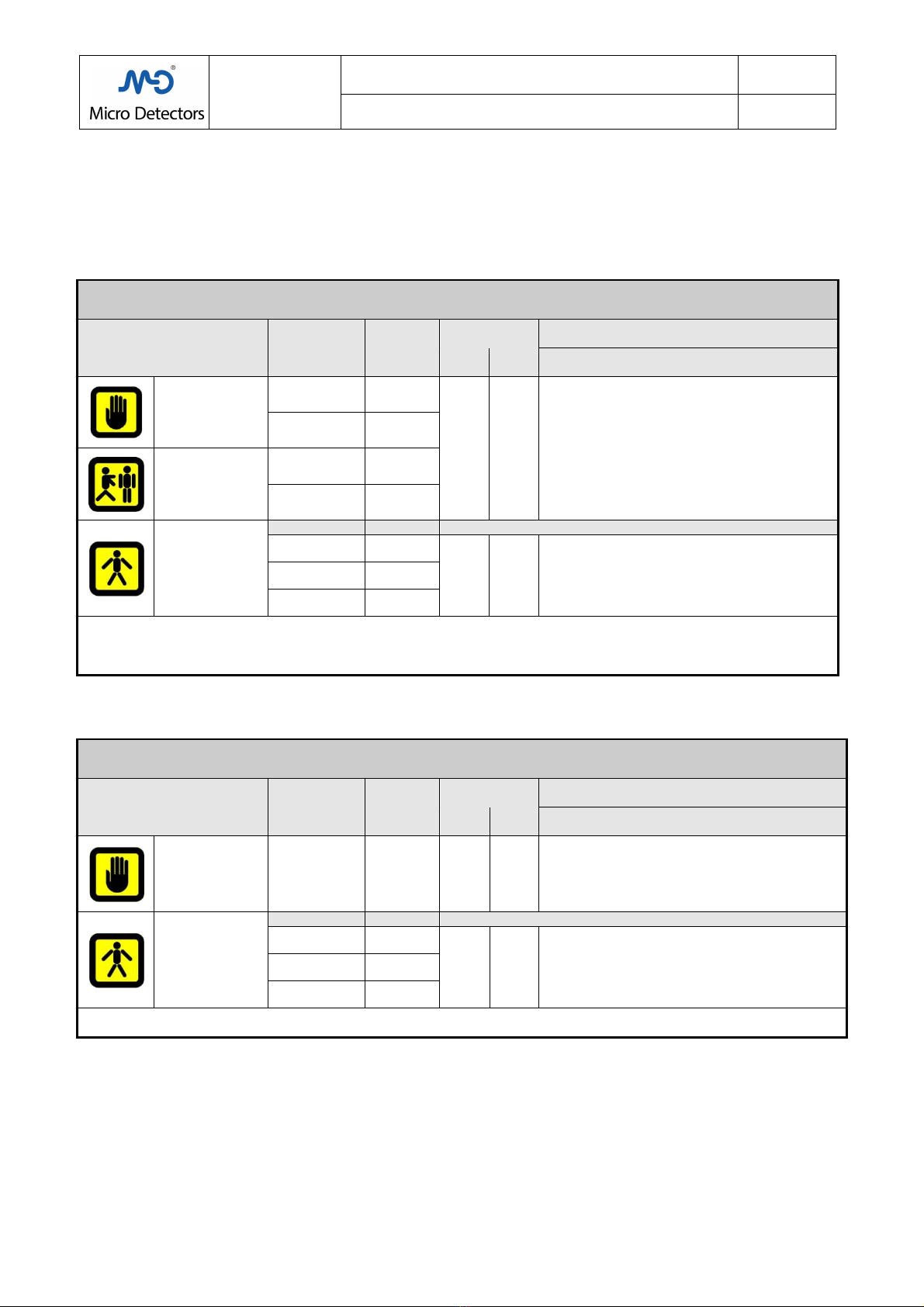
HAND
PROTECTION
Curtain of beams
30 160 to 1510
0 to 4 0 to 12
LS2*/**-*** Standard
LS2*/**-***B Base
(1)
LS2*/**-***M Master
(2) (3)
LS2*/**-***F Final Slave
(3)
LS2*/**-***S Intermediate Slave
(2) (3)
40
(1)
160 to 1510
LIMBS AND
PRESENCE
PROTECTION
Curtain of beams
50 160 to 1510
90 310 to 1510
ACCESS
PROTECTION
Multiple beams
No. of BEAMS
PITCH
2 500
0 to 4 0 to 12
LS2*/**-*** Standard
LS2*/**-***B Base
(1)
LS2*/**-***M Master
LS2*/**-***F Final Slave
LS2*/**-***S Intermediate Slave
3 400
4 300
NOTES:
T e
Base
[B]
models ave limited functions (automatic restart only).
(1): For all models wit resolution 40mm and Base models it is necessary to verify availability; (2): For t e Master and
Intermediate Slave models t e optical eig t 160 is not available; (3): for t e Master, Slave and Final Slave models wit
resolution 90mm t e optical eig t 1510 is not available.
Tab.:2; Chap.:3
3.4 Availability of models with IP69K protection
LS2 SERIES
IP69K
OPTICAL FEATURES
APPLICATION
RESOLUTION
HEIGHT
OF OPTICS
SELECTABLE
RANGES AVAILABLE MODELS
(mm) (mm)
Low
(m)
Hig
(m) SEE ALSO NOTES
HAND
PROTECTION
Curtain of beams
30 160 to 1510
0 to 3 0 to 10
LS2*/30-***K standard, wit out eater (-10 to 55°C)
LS2*/30-***H standard, wit eater (-25 to 50°C)
Models wit standard range only
ACCESS
PROTECTION
Multiple beams
No. of BEAMS
PITCH
2 500
0 to 3 0 to 10
LS2*/**-***K standard, wit out eater (-10 to 55°C)
LS2*/**-***H standard, wit eater (-25 to 50°C)
Models wit standard range only
3 400
4 300
NOTES:
All models are specified for applications in t e food industry, IP69K, (was ing at ig pressure: 100 bar, 80 ° C)
Only Standard models available (wit complete functions: Automatic, Restart, EDM in all combinations)
Tab.:3; Chap.:3
M.D. Micro Detectors
Strada S. Caterina, 235
41122 Modena Italy
Tel. +39 059 420411
Fax +39 059 2539 3
www.microdetectors.com
m
M.D. Micro Detectors
CAT8ELS12509
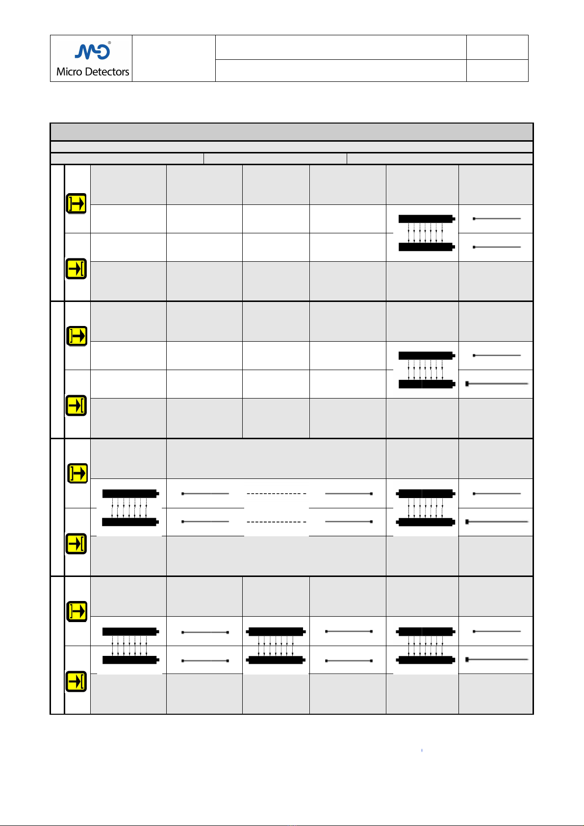
3.5
Possibility of interconnection of the available models
Tab: 4 shows the possible interconnections between models and their supply and extension cables
LS2 SERIES
AVAILABLE MODELS,
UPSTREAM devices
CONNECTOR
BASE
LS2ER/**-***B
LS2ER/**-***
LS2ER/**-***#
Final Slave model
LS2E/**-***F
Final Slave model
LS2R/**-***F
LS2ER/**-***#
Final Slave model
LS2E/**-***F
Extension
M12 5p F/F
Straight
CDP12/0H
-
Final Slave model
LS2R/**-***F
Extension
M12 5p F/F
Straight
CDP12/0H
-
Tab.:4; Chap.:3
NOTES:
For t e curtains
codes see Tab.:1, C ap. 3 and all C ap.:9, t e variables “**
eig t.
For t e complete cable codes see Tab.:1, C ap.:11, t e variable “***” indicates t e cable lengt in dm.
www.microdetectors.com
m
LS2 SERIES
SAFETY LIGHT CURTAIN TYPE 2
Installation and Operation
Manual
CAT8ELS12509
01
Possibility of interconnection of the available models
Tab: 4 shows the possible interconnections between models and their supply and extension cables
AVAILABLE MODELS,
CONFIGURATION, CONNECTORS, CABLES
DOWNSTREAM devices
HEAD
CONNECTOR
BASE HEAD
CONNECTOR
Base model
LS2E/**
Base model
LS2R/**
Standard model
LS2E/**
Standard model
LS2R/**
M12 5p F/F extension
Straight
CDP12/0H-***AC
Master model
LS2E/**
M12 5p F/F extension
Straight
CDP12/0H-***AC
Master model
LS2R/**
Extension
M12 5p F/F
Straight
-
*** AC
Intermediate
Slave model
LS2E/**-***S
Extension
M12 5p F/F
Straight
CDP12/0H-*** AC
Master model
LS2E/**
Extension
M12 5p F/F
Straight
-
*** AC
Intermediate
Slave model
LS2R/**-***S
Extension
M12 5p F/F
Straight
CDP12/0H-*** AC
Master model
LS2R/**
codes see Tab.:1, C ap. 3 and all C ap.:9, t e variables “**
-
***” indicate resolution and
For t e complete cable codes see Tab.:1, C ap.:11, t e variable “***” indicates t e cable lengt in dm.
LANGUAGE
Manual
ENGLISH
8/34
Tab: 4 shows the possible interconnections between models and their supply and extension cables
.
CONFIGURATION, CONNECTORS, CABLES
DOWNSTREAM devices
CONNECTOR
BASE
Base model
LS2E/**
-***B
M12 5p F cable
Straight
CD12M/0H-***A3
Right-angle
CD12M/0H-***C3
Base model
LS2R/**
-***B
M12 5p F cable
Straight
CD12M/0H-***A3
Right-angle
CD12M/0H-***C3
Standard model
LS2E/**
-***
M12 5p F cable
Straight
CD12M/0H-***A3
Right-angle
CD12M/0H-***C3
Standard model
LS2R/**
-***
M12 8p F cable
Straight
CD12M/0E-***A1
Right-angle
CD12M/0E-***C1
Master model
LS2E/**
-***M
M12 5p F cable
Straight
CD12M/0H-***A3
Right-angle
CD12M/0H-***C3
Master model
LS2R/**
-***M
M12 8p F cable
Straight
CD12M/0E-***A1
Right-angle
CD12M/0E-***C1
Master model
LS2E/**
-***M
M12
5p F cable
Straight
CD12M/0H-***A3
Right-angle
CD12M/0H
-
***C
3
Master model
LS2R/**
-***M
M12 8p F cable
Straight
CD12M/0E-***A1
Right-angle
CD12M/0E-***C1
***” indicate resolution and
For t e complete cable codes see Tab.:1, C ap.:11, t e variable “***” indicates t e cable lengt in dm.
M.D. Micro Detectors
Strada S. Caterina, 235
41122 Modena Italy
Tel. +39 059 420411
Fax +39 059 2539 3
www.microdetectors.com
LS2 SERIES
SAFETY LIGHT CURTAIN TYPE 2
LANGUAGE
Installation and Operation Manual
ENGLISH
M.D. Micro Detectors CAT8ELS1250901 9/34
4.0 INSTRUCTIONS FOR POSITIONING THE SAFETY LIGHT CURTAINS
4.1 Respecting the safety distance
A safety distance must be maintained between t e protection surface composed of t e beams of t e optico-
electronic
safety lig t curtain and t e point of danger.
T is distance must ensure t at, considering a maximum approac speed defined by t e standard, t e point of danger
can only be reac ed w en sufficient time as elapsed so t at t e dangerous state of t e mac ine as ended.
The safety distance in accordance with EN ISO 13855 depends:
-
in direct proportion on t e total time for stopping t e mac ine or system, w ic corresponds to t e sum of t e
individual times
of reaction of t e w ole safety c ain (t e individual response times are indicated in t e tec nical
documentation of t e safety devices and of t e mac ine itself or must be verified wit specific measures).
- in direct proportion on t e approac speed.
- in direct proportion on t e resolution of t e safety lig t curtain
, or inversely to t e number of beams for t e unit of
eig t.
If t e mac ine is subject to a specific standard of type C, t e indications of t is standard must be followed.
Danger of f
ailed recognition!
Particularly in access protection applications, people may stop in t e danger area, but not in t e optical
beam between t e Emitter and t e Receiver, and t eir presence mig t not be recognized.
Make sure t at dangerous states can only occur w en t ere are no persons in t e danger area.
Make sure t at t e system restart control is effected from a point providing full visibility of t e danger
area and t at t is control cannot be reac ed from wit in said area.
No protection function
is secure if the safety distance is not correct!
It is indispensable to mount t e safety lig t curtains at t e correct safety distance to ensure t e function
of protection.
If there is a C
-
type standard for the application you are creating, follow
its instructions!
T e following instructions apply only to an industrial environment, t at is to say w ere only adults of
normal constitution are expected to be present.
M.D. Micro Detectors
Strada S. Caterina, 235
41122 Modena Italy
Tel. +39 059 420411
Fax +39 059 2539 3
www.microdetectors.com
LS2 SERIES
SAFETY LIGHT CURTAIN TYPE 2
LANGUAGE
Installation and Operation Manual
ENGLISH
M.D. Micro Detectors CAT8ELS1250901 10/34
4.2 How to calculate the safety distance S in conformity with EN ISO 13855 and EN ISO 1385
Here we give t e general procedures for calculating t e minimum safety distance S
, t ese instructions must be followed
if t ere is not a specific standard of type C for t e mac ine to make safe.
Depending on t e application it is necessary to use different calculation sc emes.
In general t e formula as t is form:
S = K * T+ C
W ere…
S = [mm] Safety distance
K = [mm/s] Approac speed, a speed of 2000mm/s is indicated for t e upper limbs and 1600 for t e lower limbs.
T = [s] Total stopping time: response time of t e entire safety device + mac ine stopping time.
C = [mm]
Safety distance supplement, to ensure t at t e dangerous zone cannot be reac ed by climbing over t e
beams or inserting limbs between t e beams. It is provided by t e standard, it
takes on a fixed value or is calculated
according to t e optical features of t e safety lig t curtain and its utilization in t e application.
The reaction time of the safety light curtain alone is stated on the product label of the
Receivers and in this document in the tables of Chap.:9.
In the case of a chain connection the reaction time of the safety light curtains corresponds to
the sum of all the individual times of the Receiver elements in the chain.
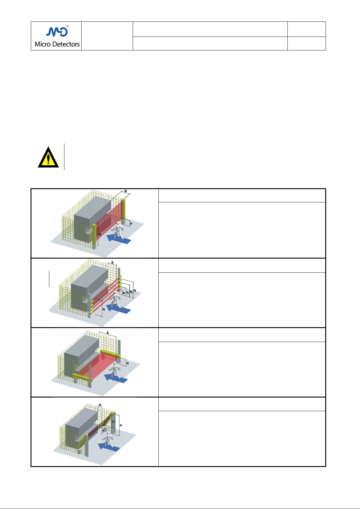
The standard considers different methods of approach:
1) PERPENDICULAR APPROACH
Safety light curtain in vertical position.
Angle between safety lig t curtain and surface of 90° ±5°
2) PERPENDICULAR APPROACH
Safety light grid in vertical position.
Angle between safety lig t curtain and surface of 90° ±5°
3) HORIZONTAL APPROACH
Safety light curtain in horizontal position.
Angle between safety lig t curtain and surface of 0° ±5°
4) OBLIQUE APPROACH
Safety light curtain in angled position.
Two cases are considered for different angle values α
αα
α
Wit α
αα
α ≥30° we ave t e perpendicular approac
Wit α
αα
α <30° we ave t e orizontal approac
Tab.:1; Chap.:4
M.D. Micro Detectors
Strada S. Caterina, 235
41122 Modena Italy
Tel. +39 059 420411
Fax +39 059 2539 3
www.microdetectors.com
LS2 SERIES
SAFETY LIGHT CURTAIN TYPE 2
LANGUAGE
Installation and Operation Manual
ENGLISH
M.D. Micro Detectors CAT8ELS1250901 11/34
●
Calculate S with the following procedure for applications of protection with
safety light
curtain
s over
which it is possible to climb.
If a safety lig t curtain
is installed wit out any supplementary mec anical protection on t e top, and t erefore it is
possible to enter t e protected area from above, it is necessary to define t e safety distance considering two met ods:
- Access from above.
- Access t roug t e beams.
-
Access from below, not considered now, can be excluded if t e lowest beam as a maximum eig t of 200mm from
t e surface, or by installing mec anical protection.
T e safety distance, considering access from above, must be suc as not to allow rea
c ing t e danger area; t is safety
distance is obtained from Tab,:2 of ISO 13855, ere Tab.:3; C ap.:4
T e safety distance, considering access between t e beams, is obtained from t e procedures indicated below t at
envisage access only t roug t e beams.
T e safety distance to c oose will be t e greater one of t e two.
To ave indications of t e dimensions of any mec anical protection to superimpose on t e safety lig t curtain
or only
mec anical protection not closed on t e top part, please refer to standard EN ISO 1385 .
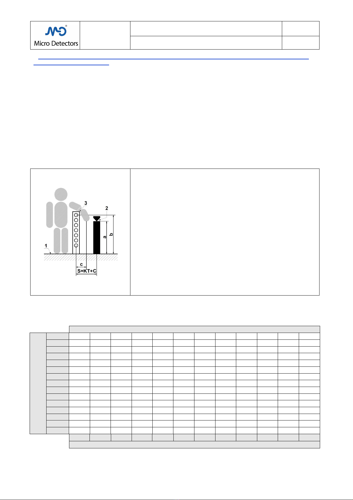
1)
Reference surface
2)
Dangerous point or danger area
3)
P oto-electric safety lig t curtain
a)
Heig t above t e surface of t e dangerous point or of t e ig er point
of t e danger area
b)
Heig t above t e surface of t e top of t e optical window of t e
safety lig t curtain.
c)
Minimum safety distance so as not to reac t e danger area from
above is obtained from Tab.:2 of ISO 13855 ere Tab.:3; C ap.:4
C)
Lengt of t e pat of t e limb
t roug t e beams, from t e level of
t e optics until t e two optics are completely darkened (resolution)
KT)
Route of t e limb t roug t e
safety lig t curtain
during t e total time
T of t e response to stopping, considering a specific approac speed
K
S)
Minimum safety distance between t e
safety lig t curtain
and danger
area calculated considering access t roug t e beams, see t e
following cases
Tab.:2; Chap.:4
Tab.:2 from ISO 13855/ EN999
[c] MINIMUM DISTANCE TO IMPLEMENT BETWEEN THE CURTAIN AND DANGER AREA
[a] HEIGHT OF THE DANGER AREA
2600 0 0 0 0 0 0 0 0 0 0 0 0
2500 400 400 350 300 300 300 300 300 250 150 100 0
2400 550 550 550 500 450 450 400 400 300 250 100 0
2200 800 750 750 700 650 650 600 550 400 250 0 0
2000 950 950 850 850 800 750 700 550 400 0 0 0
1800 1100 1100 950 950 850 800 750 550 0 0 0 0
1600 1150 1150 1100 1000 900 800 750 450 0 0 0 0
1400 1200 1200 1100 1000 900 850 650 0 0 0 0 0
1200 1200 1200 1100 1000 850 800 0 0 0 0 0 0
1000 1200 1150 1050 950 750 700 0 0 0 0 0 0
800 1150 1050 950 800 500 450 0 0 0 0 0 0
600 1050 950 750 550 0 0 0 0 0 0 0 0
400 900 700 0 0 0 0 0 0 0 0 0 0
200 600 0 0 0 0 0 0 0 0 0 0 0
0 0 0 0 0 0 0 0 0 0 0 0 0
900 1000 1100 1200 1300 1400 1600 1800 2000 2200 2400 2600
[b] HEIGHT OF THE TOP EDGE OF THE OPTICAL WINDOW OF THE CURTAIN
Tab.:3; Chap.:4

M.D. Micro Detectors
Strada S. Caterina, 235
41122 Modena Italy
Tel. +39 059 420411
Fax +39 059 2539 3
www.microdetectors.com
LS2 SERIES
SAFETY LIGHT CURTAIN TYPE 2
LANGUAGE
Installation and Operation Manual
ENGLISH
M.D. Micro Detectors CAT8ELS1250901 12/34
●
Calculate S with the following procedure for finger or hand protection applications, with vertical
curtains (90° ±5°) having the stated resolution D.
Resolution Formula Description
D≤40 (mm) S (mm) = 2000 * T + 8x(D-14)
From finger protection to and
protection
If t ere is a value S<100mm, use S=100mm.
If t ere is a value S>500mm, it is permissible to calculate again using t e approac speed 1600 m/s:
S (mm) = 1600 * T + 8x(D-14)
If from t is new calculation t ere is a value S<500mm, use S=500mm.
If t ere are any remaining uncontrolled access areas, t ey must ave an access widt of ≤ 5mm
to prevent limbs from
reac ing t e danger zone, ot erwise it is necessary to add more protection.
● Calculate S with the following procedure for upper limb protection applications, with vertical curtains
(90° ±5°) having the stated resolution D.
Resolution Formula Description
40< D (mm) ≤ 0 S (mm) = 1600 * T + 850 Limb Protection
T e eig t off t e ground of t e lowest beam must be P≤300mm.
T e eig t off t e ground of t e ig est beam must be H≥900mm.
● Calculate S with the following procedure and use the beam height indicated off the reference surface for
access protection applications, with vertical curtains (90° ±5°) having stated resolution D.
Resolution Formula Description
D> 0 (mm) S (mm) = 1600 * T + 850 Access protection
For curtains in a row, t e lowest beam must be no ig er t an 300mm
and t e ig er one must be no lower t an
1200mm.
W en using curtains wit multiple beams, it is necessary to observe t e eig ts of t e beams off t e
reference surface
indicated in t e following table:
No. of
Beams
P1
(mm)
P2
(mm)
P3
(mm)
P4
(mm)
2
400
900
3
300
00
1100
4
300
600
900
1200
Tab.:4; Chap.:4
● Use S and the beam height off the roller conveyor as stated for curtains with two or three beams in
protection applications for passageways for palletizers and depalletizers (machines subject to the C-type
product standard: EN 415-4).
No. of
Beams
P1
(mm)
P2
(mm)
P3
(mm)
S
(mm)
2
400
900
1200
3
400
800
1200
900
Tab.:5; Chap.:4
●
Calculate S with the following procedure for body protection applications, with
curtain
s parallel to the
direction of approach (0° ±5°) having height H off the surface and resolution D.
Resolution Formula Description
116≥ D≥50 (mm)
S (mm) = 1600 * T + C
C (mm) = (1200-0,4*H); C ≥ 850
D (mm) ≤ (H/15) + 50
15* (D – 50) ≤ H (mm) ≤ 1000
Access and presence protection
If C takes on values below 850 (mm), use C=850.
T e eig t of t e curtain off t e ground must be H≤1000 (mm).
For H>300mm install supplementary protection to avoid t e risk of access from beneat .
It is possible to use smaller resolutions t an 50mm, but t is brings no advantage (t e minimum distance off t e
ground is null even wit a resolution of 50mm).
M.D. Micro Detectors
Strada S. Caterina, 235
41122 Modena Italy
Tel. +39 059 420411
Fax +39 059 2539 3
www.microdetectors.com
LS2 SERIES
SAFETY LIGHT CURTAIN TYPE 2
LANGUAGE
Installation and Operation Manual
ENGLISH
M.D. Micro Detectors CAT8ELS1250901 13/34
5.0 MINIMUM DISTANCE FROM REFLECTING SURFACES
T e optical beams of t e Emitter
, aving a beam angle t at is not null, can partly be diverted by reflective surfaces
located near to t e curtains. T is may mean t at a break in t e direct pat of t e optical beam is not d
etected, w ic is
w y all reflective surfaces and reflective objects (in any position t ey may ave wit respect to t e controlled area,
above, under, inside or outside) must respect a minimum distance from t e direct pat of t e beams of t e
safety lig t
curtain.
Indication
It is likewise important to respect t e minimum distance between t e Emitter and Receiver
indicated by
t e manufacturer, in some cases t e minimum distance may be greater t an zero, especially for long-
range models.
At smaller
minimum distances t an t e ones stated, t e beam angle may ave an unpredictable breadt
and so t e safety distance may not be definable wit certainty.
W en using diverter mirrors, consider t at t e minimum distance from reflective surfaces must be
respec
ted for all t e rectilinear segments of t e beams, considering t e sides bot inside and outside t e
protected zone.
A reflective surface is any s iny surface, even a black one.
Any damage or opacification of t e optics or inclusion of slabs of transparent
or, even worse,
semitransparent material on t e optical pat can produce an increase in t e beam angle.
C ecking t e capacity of detection wit t e test rod, performed in t e intermediate
and at t e ends of t e
controlled area, is an effective procedure t
o exclude t e presence of dangerous reflections, see also
C ap.:13.4.
5.1 How to calculate the minimum distance from reflective surfaces
T e safety lig t curtains LS2 respect t e maximum beam angle defined by IEC / EN 61496-2 for Type 2 (a/2=±5°),
or
less.
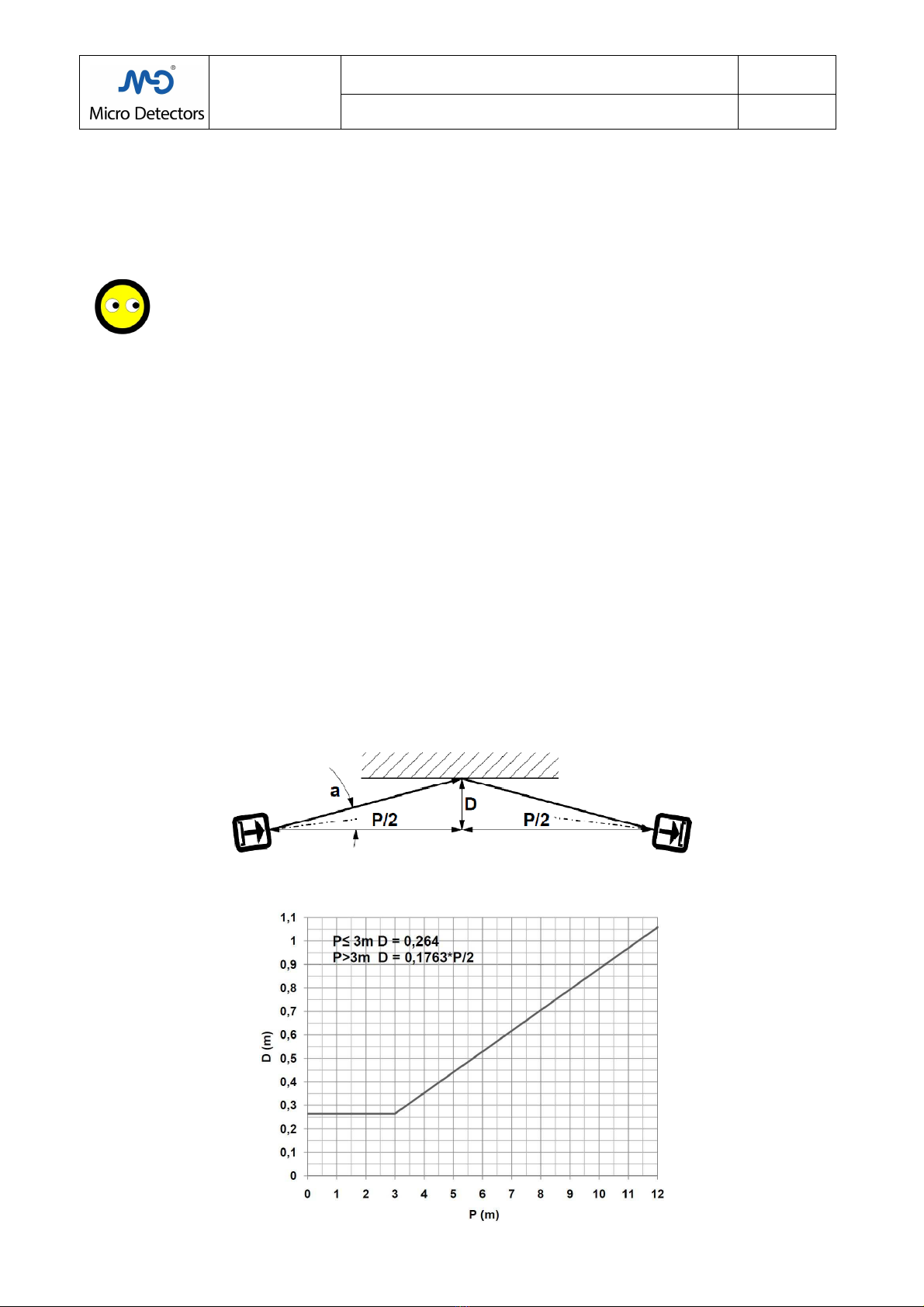
T e safety distance D is calculated considering t e entire beam angle a=10° and t e safety lig t curtain
s reciprocally
orientated towards t e reflective surface by an angle a
, in t is way we consider t e case of alignment at t e limit of
reciprocal visibility between t e Emitter and Receiver, but w ic is more dangerous due to t e effects of t e reflection.
T e safety distance D to take P ≥3m is calculated as follows:
D=tan(10°)*P/2 = 0.1 63*P/2
For ranges less t an 3m t e value calculated at 3m applies:
D = 0.1 63*1.5=0.264m
Fig.:1; Chap.:5; t is figure s ows t e worst borderline case t at can occur: safety lig t curtains not perfectly aligned,
but tilted by an angle a/2 towards a reflective surface
.
Fig.:2; Chap.:5; minimum distance “D” to maintain for t e reflective surfaces in relation to t e range “P”.
M.D. Micro Detectors
Strada S. Caterina, 235
41122 Modena Italy
Tel. +39 059 420411
Fax +39 059 2539 3
www.microdetectors.com
LS2 SERIES
SAFETY LIGHT CURTAIN TYPE 2
LANGUAGE
Installation and Operation Manual
ENGLISH
M.D. Micro Detectors CAT8ELS1250901 14/34
6.0 COMMISSIONING
6.1 Mechanical mounting
T is device is suited to work in protected environments, not outdoors.
It is extremely important to secure t e safety lig t curtains to a rigid structure, not subject to deformation or strong
vibration.
C oose t e position of t e Receiver so as not to subject it to strong sources of natural or artificial lig t or to luminous
interference by ot er sensors.
Mount t e Emitter and Receiver facing eac ot er, at t e same eig t off t e reference surface and wit t e same
orientation (refer to t e BASE side t at is t e display side), t e reciprocal distance must be wit in t e field of t e
specification. To secure t e safety lig t curtains to a support use t e specific inserts to apply to t e rear groove and t e
brackets normally provided.
If t ere is vibration in t e application, but still compatible wit t e optical alignment, use t e damping supports
available as accessories.
In t is p ase classic tools suc as a plumb line and/or a spirit level may be useful.
To facilitate t e first p ase of alignment, it is possible to use t e specific LASER STL 01 S accessory for safety lig t
curtains wit a profile of 28x30mm.
Temporarily block t e Emitter and Receiver so t ey are aligned wit and parallel to eac ot er.
Danger!
To perform t e next steps it is necessary to power t e Emitter and Receiver, make sure t at during t is
p ase t e mac ine's movements are blocked irrespective of t e state t at t e Receiver will take on; an
effective manner to obtain t is is to p ysically cut off t e supply to t e actuators by permanently
disconnecting t eir supply cables.
6.2 Alignment
1) W en switc ing on t e LED 1 of t e Emitter will be RED for t e duration of t e power-on, if afterwards t e LED
makes two s ort GREEN flas es t e Hig range function is active, if t e LED makes 2/3 RED flas es, t e TEST is
probably open and t ere is no emission (jumper TEST to proceed), if t e LED is illuminated GREEN it means t at t e
Emitter is working. In case of difficulty wit alignment it is advisable to temporarily activate t e Hig range function, if
it is not already enabled, so as to facilitate it. Refer to C ap.: 6.3 to verify t e Emitter and Receiver configuration mode
and to C ap.:8 for t e meaning of t e indications.
2) If it is possible to c oose or temporarily c ange t e configuration of t e Receiver, it is advised to use t e “Automatic
Restart wit out EDM” mode, t at is able to clearly signal t e state of LIGHT and outputs ON lig ting up LED 3, t at in
t is case will be GREEN; if t e Receiver as been configured differently (restart interlock wit or wit out EDM), observe
instead LED 2, t at in t is case will be YELLOW, indicating t e state of LIGHT, but outputs OFF; YELLOW LED 2 will be
blinking in case of MASTER on LIGHT connected to slaves on DARK.
To simplify any Receiver will be on light if LED 3 is GREEN or LED 2 is YELLOW on steady or blinking.
3) Now try adjusting t e Receiver around t e original position and define a zone in w ic t e Receiver is in t e LIGHT.
More careful alignment t an as obtained normally could be ensured by temporarily darkening t e optics of t e Receiver
wit opaque ad esive tape precisely covering alf of t e optical window and t en seeking t e condition of lig t under
t ese conditions; on obtaining t e condition of LIGHT, on removing t e tape t e signal will be at least wit margin 2.
Now c eck t at wit moderate mec anical stresses applied to t e safety lig t curtain it remains in t e LIGHT. Now
proceed wit step 5).
4) If you are not able to bring t e Receiver into t e lig t or to ensure an adequate level of margin, correct t e position
of t e Emitter and try to align t e Receiver again, step 3).
5) Again temporarily lock t e Receiver in t e intermediate of t e found zone and c eck it as an acceptable
arrangement. If it is acceptable proceed wit step 6), if it is not acceptable correct t e alignment of t e Emitter
accordingly and realign t e Receiver, step 3).
6) After alignment, permanently lock t e safety lig t curtains and restore all t e required conditions for t e application,
including t e electric connections.
) Have complete functional testing carried out on t e safety lig t curtain, including a resolution test and c ecking for
t e presence of reflective surfaces, using a test rod, of t e same diameter as t e rated resolution.
8) Make sure t at during normal use no unfavourable conditions arise around, suc as:
- presence of ot er Emitters or ot er brig t or modulated sources of lig t able to it t e Receiver,
- presence or movement of reflective objects near t e area,
- transparent or semi-transparent materials inserted in t e pat of t e beams,
- systematic presence of dust or spray of liquids able to foul t e surface of t e optics.
Indication
Correct optical alignment wit good excess gain enables avoiding instability in t e be aviour of t e
safety
lig t curtain
, reducing optical interference, reflections from s iny surfaces and in general ensuring greater
safety.
Danger!
Remember to restore t e wiring and c eck t e required met ods of operation of t e application again.
M.D. Micro Detectors
Strada S. Caterina, 235
41122 Modena Italy
Tel. +39 059 420411
Fax +39 059 2539 3
www.microdetectors.com
LS2 SERIES
SAFETY LIGHT CURTAIN TYPE 2
LANGUAGE
Installation and Operation Manual
ENGLISH
M.D. Micro Detectors CAT8ELS1250901 15/34
6.3 Electrical installation.
Before proceeding carefully read t e data of Tab.:1; C ap.:7 in t e sections: Supply, Outputs and Connections.
See Tab.: 1-4 in t is c apter to make t e required connections for t e supply, load and configuration for t e
connectors. Preferably use prewired connectors; for t e Master/Slave connections use only extensions.
Use PELV power supplies, in accordance wit C ap.6.4. of EN 60204-1.
If using a non-stabilized power supply, t e transformer must ave double insulation and adequate power, t e
secondary winding must be 18V, use a bridge rectifier, use a filtering capacitor wit a minimum value of 2200µF for
absorptions up to 1A, for ig er absorptions add 2200µF for every extra Ampere.
Connect t e supply cables directly to t e source and not downstream of ot er power or ig ly inductive devices.
Run t e cables of t e safety lig t curtains in dedicated raceways or, w ere only signals run; do not use raceways t at
carry power cables.
Make sure t e functional eart cable (FE) is connected directly to t e general ground terminal.
Before inserting t e connector, c eck t at t e mains voltage and t e supply voltage are wit in t e required limits, apply
t e connector and c eck again t at t e supply voltage as a correct nominal value and remains wit in t e limits defined
in all t e working conditions, c eck t e limits in t e two extreme conditions of minimum and maximum absorption of all
of t e devices connected to t e same power supply, especially if t is is not a stabilized power supply.
In t e following tables t e colours of t e cables and LEDs are indicated wit t e abbreviations defined in IEC 60707 in
Englis
BK BN RD YE OG GN BU GY WH PK VT
Black Brown Red Yellow Orange Green Blue Grey W ite Pink Violet
SERIE LS2
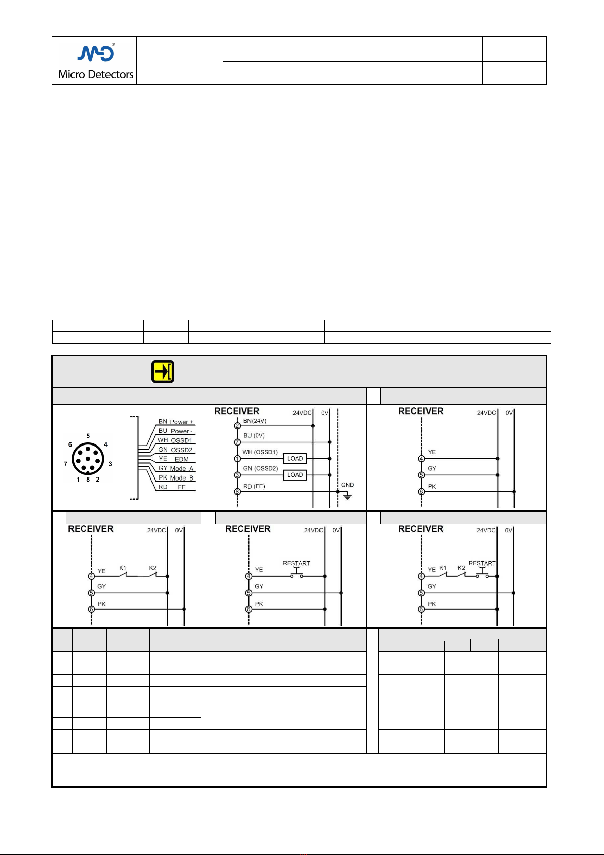
RECEIVER
CONNECTOR AND CABLE EXIT WITH EIGHT POLE
S
Standard and Master models: LS2R/**-***; LS2R/**-***M (connector exit)
Standard models, IP69K: LS2R/**-***K (cable exit)
M12, 8
pole
Male connector
8
-
wire cable
Only K models Power supply and loads 1
Automatic restart without EDM
2
Automatic restart with EDM
3
Manual restart without EDM
4
Manual restart with EDM
Pin
Color Signal Type Description
CONFIGURATION
LOGIC
Pin 4 Pin 5
Pin 6
Function
1 WH OSSD1 OUT
First safety static output (PNP)
24V
DC
24V
DC
0V AUTO
2 BN 24V
DC
POWER
Power supply input
3 GN OSSD2 OUT
Second safety static output (PNP)
K1+K2
+24V
DC
24V
DC
0V AUTO
+ EDM
4 YE EDM IN
Connection to Restart
and/or external
control contacts (EDM).
5 GY Mode_A IN Selection of t e Start/Restart/EDM mode Restart
+24V
DC
0V 24V
DC
MANUAL
6 PK Mode_B IN
BU 0V POWER
Supply voltage reference
K1+K2+Restart
+24V
DC
0V 24V
DC
MANUAL
+ EDM
8 RD FE GND
Functional eart
NOTE:
On t ese Standard and Master models it is possible to c oose t e operating modes by c anging t e wiring. By using t e EDM
function it is possible to extend t e safety control to t e contactors controlled downstream, t at must be t e type wit guided
contacts and approved for safety applications.
With this model of curtain you can use the relay module SB300, but the EDM input must be connected.
Tab.:1; Chap.:6

M.D. Micro Detectors
Strada S. Caterina, 235
41122 Modena Italy
Tel. +39 059 420411
Fax +39 059 2539 3
www.microdetectors.com
LS2 SERIES
SAFETY LIGHT CURTAIN TYPE 2
LANGUAGE
Installation and Operation Manual
ENGLISH
M.D. Micro Detectors CAT8ELS1250901 16/34
SERIES
LS2
RECEIVER
CONNECTOR EXIT WITH FIVE POLES
Base models: LS2R/**-***B
M12, 5 pole male Diagram Wiring
Pin
Colour Signal Type Description
1 BN 24V
DC
POWER Power supply input
2 WH OSSD1 OUT First safety static output (PNP)
3 BU 0V POWER Power supply reference
4 BK OSSD2 OUT Second safety static output (PNP)
5 GY FE GND Functional eart
NOTE:
T ese Base models wit automatic restart do not ave t e EDM function, t e device downstream must t erefore be able to
control its own safety integrity independently.
With this model of curtain yo
u can not
use the relay module SB300
, because the EDM input is not available.
Tab.:2; Chap.:6
SERIES LS2
RECEIVER
CABLE EXIT WITH TEN POLES
Models IP69K, thermostated: LS2R/**-***H
10-wire cable Power supply and loads Heater power 1
Automatic restart
without EDM
2
Automatic restart with EDM
3
Manual restart without EDM
4
Manual restart with EDM
Colour
Signal Type Description
CONFIGURATION LOGIC
YE GY PK
Function
BN 24V
DC
POWER
Power supply input
24V
DC
24V
DC
0V
AUTO
BU 0V POWER
Supply voltage reference
WH OSSD1 OUT
First safety static output (PNP)
K1+K2
+24V
DC
24V
DC
0V
AUTO
+ EDM
GN OSSD2 OUT
Second safety static output (PNP)
YE EDM IN
Connection to Restart and/or external control
contacts (EDM). Restart
+24V
DC
0V
24V
DC
MANUAL
GY Mode_A IN Selection of t e Start/Restart/EDM mode
PK Mode_B IN
K1+K2
+Restart
+24V
DC
0V
24V
DC
MANUAL
+ EDM
BK Heater 0 POWER Heater supply common
VT Heater P POWER
Heater supply 24V DC o AC
X 0V 0V NOT
ALLOWED
RD FE GND
Functional eart
X 24VDC 24VDC
NOTA:
On t ese Standard models it is possible to c oose t e operating modes by c anging t e wiring. By using t e EDM function it
is possible to extend t e safety control to t e contactors controlled downstream, t at must be t e type wit guided contacts
and approved for safety applications.
T e supply voltage of t e t ermostated eater can be indifferently 24VDC or 24VAC.
With this model of curtain you can use the relay module SB300, but the EDM input must be connected.
Tab.:3; Cap.:6

M.D. Micro Detectors
Strada S. Caterina, 235
41122 Modena Italy
Tel. +39 059 420411
Fax +39 059 2539 3
www.microdetectors.com
LS2 SERIES
SAFETY LIGHT CURTAIN TYPE 2
LANGUAGE
Installation and Operation Manual
ENGLISH
M.D. Micro Detectors CAT8ELS1250901 17/34
SERIE LS2
EMITTER
CONNECTOR AND CABLE EXIT WITH FIVE POLE
S
Standard and Master models: LS2E/**-***; LS2E/**-***M (connector output)
Models IP69K: LS2E/**-***K (cable output)
For the emitters the Base and Standard models have identical functions.
M12, 5 pole
Male connector
5-pole cable
Only models K Wiring for high range Wiring for low range
Pin
Colour
Signal Type Description CONFIGURATION LOGIC
WH BK Function
1 BN 24V
DC
POWER
Power supply input
LO LO
Test
2 WH Range L/Test IN
Range or Test selection
input
LO HI
Hig range
3 BU 0V POWER
Supply voltage reference
HI LO
Low range
4 BK Range H/Test IN
Range or Test selection input
HI HI
Not admitted
5 GY FE GND
Functional eart
Levels: LO = <5V or open; HI = 11 to 30V
NOTE: T e Test contact is necessary only if t e safety c ain of t e receiver downstream must be periodically c ecked. If t e Test is
not necessary (t e safety lig t curtain as already been tested independently) replace t e contact wit direct wiring at
+24V
DC
.
Tab.:4; Chap.:6
SERIE LS2
EMITTER
CABLE EXIT WITH EIGHT POLES
Models IP69K, thermostated: LS2E/**-***#H
8-pole cable
Only models H Wiring for high range Wiring for low range
Colour
Signal Type Description CONFIGURATION LOGIC
WH BK Function
BN 24V
DC
POWER Power supply input LO LO
Test
WH Range L/Test IN Range or Test selection input LO HI
Hig range
BU 0V POWER Supply voltage reference HI LO
Low range
GN Range H/Test IN Range or Test selection input HI HI
Not admitted
PK None N.C. Not connected
Levels: LO = <5V or open; HI = 11 to 30V
YE Heater 0 POWER Heater supply common
RD
Heater
P
POWER
Heater
suppl
y
24V DC o AC
GY FE GND Functional eart
NOTA:
T e Test contact is necessary only if t e safety c ain of t e receiver
downstream must be periodically c ecked. If t e Test is
not necessary (t e safety lig t curtain as already been tested independently) replace t e contact wit direct wiring at
+24V
DC
.
T e supply voltage of t e t ermostated eater can be indifferently 24VDC or 24VAC.
The PK cable is not connected internally.
Tab.:5; Chap.:6

M.D. Micro Detectors
Strada S. Caterina, 235
41122 Modena Italy
Tel. +39 059 420411
Fax +39 059 2539 3
www.microdetectors.com
LS2 SERIES
SAFETY LIGHT CURTAIN TYPE 2
LANGUAGE
Installation and Operation Manual
ENGLISH
M.D. Micro Detectors CAT8ELS1250901 18/34
LS2
SERIES
RECEIVER
AND EMITTER
CONNECTORS FOR INTERCONNECTION OF MASTER/SLAVE/FINAL
WITH FIVE POLES
LS2*/**-***M; LS2*/**-***S; LS2*/**-***F
M12, 5 pole male Head connector
Master/Slave
Base connector
Slave/Final
Pin
Colour Signal Type Description
1 BN 24V
DC
POWER
Power supply (supply line for t e upstream device)
2 WH Line 1 IN/OUT
Communication line 1
3 BU 0V POWER
Power supply reference (supply line for t e upstream
device)
4 BK Line 2 IN/OUT
Communication line 2
5 GY FE GND
Functional eart
NOTE: Preferably use Female/Female pre-wired extension cables (it is not permitted to access t e connection lines).
Tab.:6; Chap.:6
M.D. Micro Detectors
Strada S. Caterina, 235
41122 Modena Italy
Tel. +39 059 420411
Fax +39 059 2539 3
www.microdetectors.com
LS2 SERIES
SAFETY LIGHT CURTAIN TYPE 2
LANGUAGE
Installation and Operation Manual
ENGLISH
M.D. Micro Detectors CAT8ELS1250901 19/34
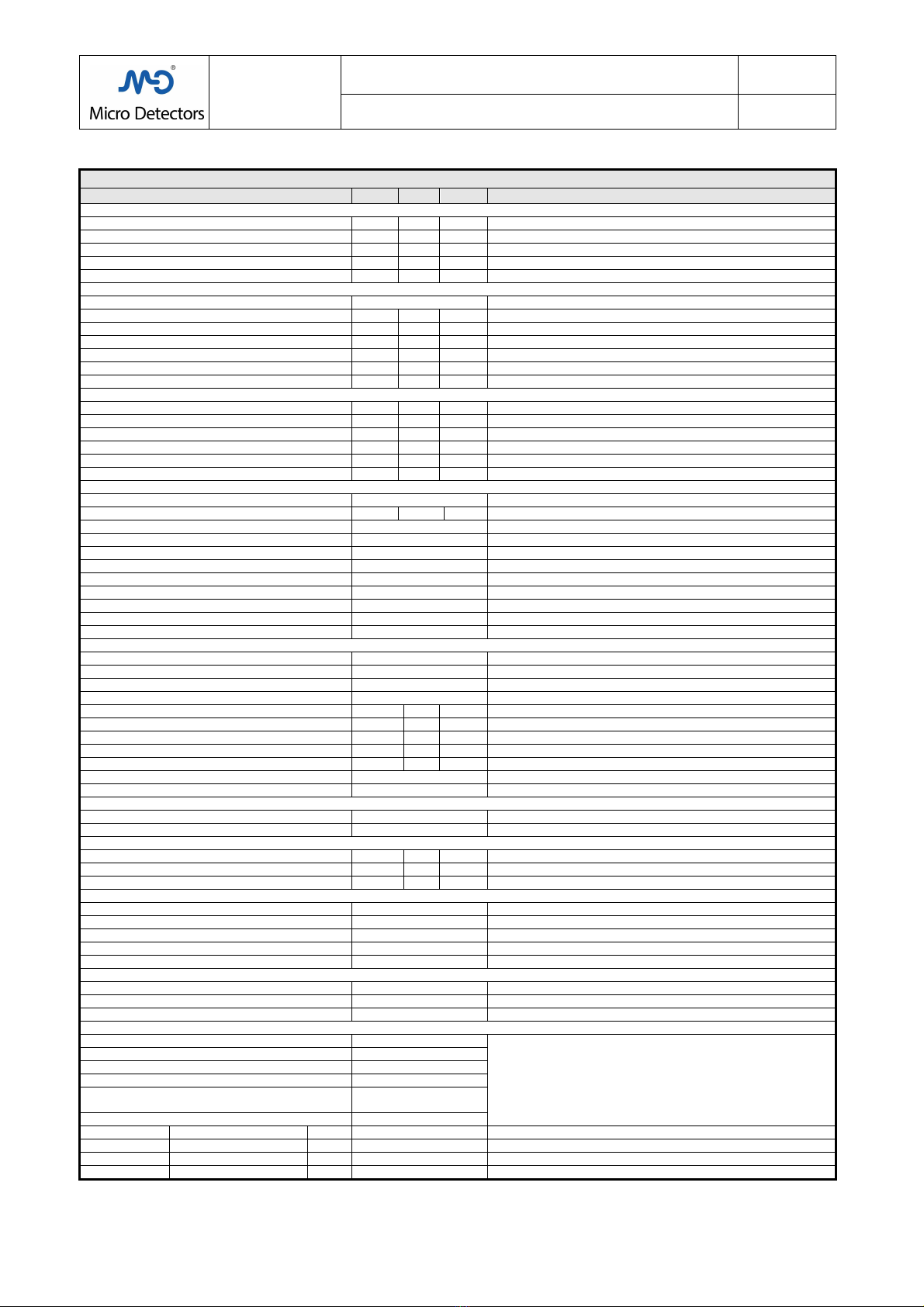
.0 TECHNICAL SPECIFICATIONS.
LS2 SERIES TECHNICAL SPECIFICATIONS
PARAMETERS
Min.
Nom.
Max.
NOTES
Power supply
Supply voltage
V
DC
19.2
24
28.8
From PELV power supply according to EN 60204
-
1 C ap.6.4
Residual
ripple
V
1.2
T e limits of t e supply
voltage
must not be exceeded
Absorbed power, Receiver
W
2
Excluding t e load
Absorbed power, Emitter
W
1
Absorbed power, Heater
W
2
10
Models H, IP69K wit eater, see C ap.:10, Tab.: 4
Outputs
(OSSDs)
Output type
2 x PNP
Completely protected safety outputs.
Current
mA
400
Hig er values are interpreted as overload or s orting
Voltage drop @400mA
V
1.2
Reduction in output voltage compared to t e supply
voltage
Equivalent resistive load
Ω
60
Lower values are interpreted as s orting
Leakage current
mA
2
Value at
w ic t e OFF state of t e load must be guaranteed
Voltage OFF
V
0.5
Value at w ic t e OFF state of t e load must be guaranteed
Tolerated capacitive load
µF
0.82
Hig er values can be interpreted as s orting.
Reaction times
Time delay before
availability
ms
500
After application of t e power supply
DARK response time (OSSDs OFF)
ms
2.5
20
Depending on t e number of optics, see tables in C ap.9
LIGHT response time
(OSSDs ON)
ms
400
It guarantees t is minimum duration of DARK pulse
Duration of t e test pulse of OSSDs
µs
100
S ould be ignored by downstream devices.
Restart control duration
s
0.1
5
Valid for input sequence
L
►
H
►
L
and indicated duration
H
Test input signal duration
ms
4
Valid if it as at least t e stated
duration
Safety parameters
Type
2
IEC 61496
-
1, 2004; IEC 61496
-
2, 2006
Optical beam angle
Deg
.
±5°
IEC 61496
-
2, 2006
Inco erent lig t emitted
nm
950
LED, RG 0 (Exempt Group), IEC 62471: 2006
-
07
Internal self
-
test
period
s
0.5
IEC 61496
-
1, 2004
Safety integrity level
SIL 2
IEC 61508, 1998
Safety integrity level
SILCL 2
IEC 62061, 2005
Performance level
PL d
ISO 13849
-
1 2006
Class
2
ISO 13849
-
1 2006
Reliability,
MTTFd
Y
ears
100
ISO 13849
-
1 2006
Resistance to faults in com. mode,
CCF
Score
80
ISO 13849
-
1 2006, IEC 62061, 2005 (min. score: 65)
Service time,
T
M
Y
ears
20
ISO 13849
-
1 2006
Ambient
Artificial lig t immunity
Acc
.
to
IEC 61496
-
2
It respects t e limits and conditions of t e stated standard
Natural lig t immunity
Acc
.
to
IEC 61496
-
2
It respects t e limits and conditions of t e stated standard
Models wit standard protection
IP65 and IP6
Dust and water protection (immersion at 1m for 60min.)
Models wit special protection
IP65, IP6 , IP69K
Transparent casing
wit standing ig
-
pressure was ing (100 bar)
Working temperature
°C
-
10
55
Wit out condensation
Working temperature IP69K models
°C
-
1
0
55
Wit out condensation, models wit out eater
Working temperature IP69K models
°C
-
25
5
5
Models wit
t ermostatic
eating
Storage temperature
°C
-
25
0
To be respected also during transportation
Humidity
%
95
Wit out condensation
Vibration
Acc.
to
IEC 61496
-
1
It respects t e limits and conditions of t e stated standard
Impact
Acc.
to
IEC 61496
-
1
It respects t e limits and conditions of t e stated standard
Range correction factors
Use of diverter mirrors
0.85
For eac diversion wit a mirror
Environmental factors
0.50 / 0.25
For t e presence of dust, vapours
/ mist, fumes (indicative
)
Connections
mm
2
0,34
To ensure t e stated maximum lengt
Total lengt of cables for supply&output
m
100
Wit cables of indicated section
Intermediate cable lengt (extensions)
m
50
Wit cables of indicated section
Dimensions / Materials,
IP6 models
Housing section
mm
28 (front) x 30
Painted aluminium; colour:
yellow
RAL 1012
Groove for fixing
mm
2/10
/
One in t e posterior side, dept / widt / widt of entry
Front window widt
mm
18mm
Useful central widt 13mm:
material
:
PMMA IR
End closings
No.
2
Material: PP + 30%GF
Closing screws
No.
4+4
Material:
Burnis ed
FE37
Dimensions / Materials, IP69K models
Housing
mm
Ø56
Material: PMMA
Sealing caps
N°
2
Material: POM C , silicone gaskets
Bridles and screws
N°
2
Material:
stainless steel AISI 316L 1.4404
Connectors
Models: LS2E/…._, B, F
1xM12 5p male
Material: Nickel-plated brass
Models: LS2E/…._, M, S
2xM12 5p male
Models: LS2R/….B, F
1xM12 5p male
Models: LS2R/…._
1xM12 8p male
Models: LS2R/….M
1xM12 8p male
1xM12 5p male
Models: LS2R/….S
2xM12 5p male
Modelli: LS2E/….K
Cable
Material: PVC, Ø 5mm, L 10
m, 5
poles
, 0,34mm
2
Modelli: LS2R/….K
Cable
Material: PVC, Ø 5mm, L 10
m, 8 poles, 0,34mm
2
Modelli: LS2E/….H
Cable
Material: PVC, Ø
6mm, L 10
m, 8 poles, 0,34mm
2
Modelli: LS2R/….H
Cable
Material: PVC, Ø 6mm, L 10
m, 10 poles, 0,34mm
2
Tab.:1; Chap.:
M.D. Micro Detectors
Strada S. Caterina, 235
41122 Modena Italy
Tel. +39 059 420411
Fax +39 059 2539 3
www.microdetectors.com
LS2 SERIES
SAFETY LIGHT CURTAIN TYPE 2
LANGUAGE
Installation and Operation Manual
ENGLISH
M.D. Micro Detectors CAT8ELS1250901 20/34
8.0 PANEL AND DIAGNOSTICS INDICATIONS
8.1 Symbols used to indicate the LED indicators modes
Indication of LED lit steadily
Indication of
LED lit intermittently wit periodical blinking.
T e number of consecutive blinks in t e period indicates an error code, see Tab.: 7 and 8
Indication of LED wit continual blinking
It is indicative of a specific error code, see Tab.: 7
Indication of LED off
Tab.:1; Chap.:8
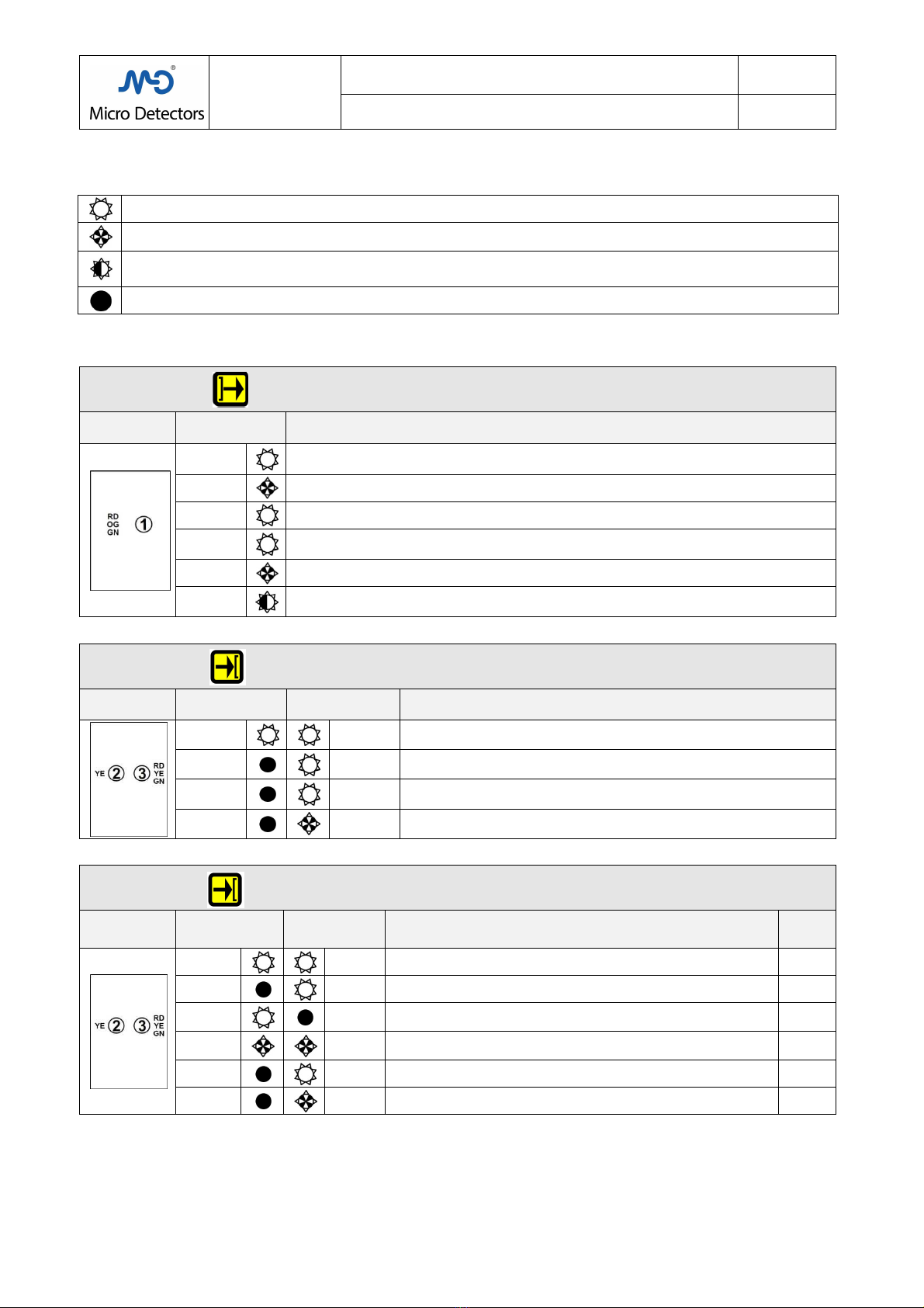
8.2 Indications of the panels
LS2
SERIES
EMITTER MODELS DISPLAY
All models: LS2E/**-***#
Display LED_1 colour
and blink Meaning
RED or
ORANGE
RED at Power_ON, as initial test of LEDs for Standard and Master models
ORANGE at Power_ON as initial test of LEDs for Slave models
GREEN
Later during Power_ON, double initial blink if t e ig range is c osen
GREEN
Standard operation
ORANGE
Test in progress (test contact open, t e test con
tact must remain closed during Power
-
ON
ot erwise an error code is signalled)
RED
Fault condition, see t e corresponding error code in Tab.:6
ORANGE
Fault condition, see t e corresponding error code in Tab.:6
Tab.:2; Chap.:8
LS2
SERIES
RECEIVER MODELS DISPLAY
Base, Slave, Final Slave models: LS2R/**-***(B,S,F)
Display LED_2 colour
and blink
LED_3 colour
and blink
Meaning
For wiring of the Base Model see Tab.:2; Chap.:6
YELLOW
RED Power_ON, as initial test of LEDs
OFF RED Broken beams, DARK and OSSDs OFF: “BREAK”
OFF GREEN
Clear beams, LIGHT
for s
lave models
, (for Master see Tab.:5)
Clear beams, LIGHT and OSSDs ON: “GUARD” for Base models
OFF RED Fault condition, see t e corresponding error code in Tab.:7
Tab.:3; Chap.:8
LS2
SERIES
RECEIVER MODELS DISPLAY
Standard models: LS2R/**-***
Display Colour LED_2
Blink
Colour LED_3
Blink Meaning
Wiring
See Tab.:1
Chap.:6
YELLOW
RED Power_ON, as initial test of LEDs 1, 2, 3, 4
OFF
RED Broken beams, DARK, OSSDs OFF: “BREAK” 1, 2, 3, 4
YELLOW
OFF
Wit manual Restart, wit o wit out EDM.
Clear beams, LIGHT, OSSDs OFF: “CLEAR”, awaiting RESTART 3, 4
YELLOW
YELLOW
Wit automatic restart and EDM
Signal level ig , LIGHT, OSSDs OFF: “CLEAR”, awaiting EDM closed
2
OFF
GREEN Clear beams, LIGHT, OSSDs ON: “GUARD” 1, 2, 3, 4
OFF
RED Fault condition, see t e corresponding error code in Tab.:7 1, 2, 3, 4
Tab.:4; Chap.:8
Table of contents
Other Micro Detectors Safety Equipment manuals


