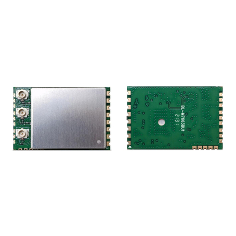
LB-Link BL-M7668BU4 User manual

BL-M7668BU4
IEEE 802.11a/b/g/n/ac 2T2R USB WiFiModule
IntegratedBluetooth2.1+EDR/4.2/5.0
Features
3. Reserving System IEEE
Std.802.11a
IEEE Std.802.11b
IEEE Std.802.11g
IEEE Std.802.11n
IEEE Std. 802.11ac Bluetooth
2.1+EDR/4.2/5.0
4. ChipSolution Mediatek
MT7668BUN
5. Size
33.0mmx70.0mm x6.0mm
ShenZhen Bilian ElectronicCo.,Ltd.
PDFpdfFactoryProwww.fineprint.cn

p
age
4of 18
BL
-
M7668BU4
IEEE 802.11a/b/g/n/ac 2T2RUSBWIFIModule&BT2.1+EDR/4.2/5.0
Filter
1. Introduction
BL-M7668BU4moduledesignisbased on MediatekMT7668BUN solution,TheMT7668BUN isa
highlyintegrated singlechipwhichhasbuilt ina2x2dual-band wireless LANradioand Bluetoothradio.
It includesBluetoothEDR and LE radiowhichcomplieswithBluetoothv2.1+EDR, v4.2, andv5.0.
TheModuleisahighlyintegratedMAC/BBP and 2.4/5GHzPA/LNAsinglechipwhichsupportsa
866.7MbpsPHYrate.TheModuleisdesignedtosupport standard-basedfeaturesinthe areasof
security, qualityofservice, andinternationalregulations, givingend usersthegreatestperformance
anytimeand inanycircumstance.Thisdocumentation describestheengineeringrequirements
specification.
RF moduleOverview
ThegeneralHWarchitectureforthe moduleisshowninFigure1.ThisWLANModuledesignisbased
on MediatekMT7668BUN.Itisahighlyintegratedsingle-chipMIMO(MultipleInMultipleOut)Wireless
LAN(WLAN)networkinterfacecontrollercomplyingwiththe802.11 specificationandBluetoothover
USB interface.It combinesaMAC,a2T2Rcapablebaseband,and RFinasinglechip.AnintelligentWi-
Fi/Bluetoothcoexistencealgorithmisimplementedtoprovide thebestharmonized Wi-FiandBluetooth
radioperformance.
5V
Figure1BL-M7668BU4Block Diagram
Dixplexer Antenna0
Dixplexer Antenna1
40MHz
Filter Antenna2
Internal
DC/DC
Internal
LDO
1.5V
2.4G TX0/RX0
1.2V
W
F_
RFIO
5G TX0/RX0
USB2.0Interface
2.4G TX1/RX1
W
F_
RFIO
5G TX1/RX1
BT_
RFIO
2.4G TX2/RX2
PDFpdfFactoryProwww.fineprint.cn

p
age
5of 18
BL
-
M
7
6
6
8
B
U
4
IEEE 802.11a/b/g/n/ac 2T2RUSBWIFIModule&BT2.1+EDR/4.2/5.0
Specificationreference
Thisspecification isbased onadditionalreferenceslisted below.
_ IEEE Std. 802.11a
_ IEEE Std. 802.11b
_ IEEE Std. 802.11g
_ IEEE Std. 802.11n
_ IEEE Std. 802.11ac
_Bluetooth2.1+EDR/4.2/5.0
SystemFunctions
Table1:GeneralSpecification asbelow:
MainChipset MediatekMT7668BUN
Operating Frequency 2.4G/5G
WiFiStandard 802.11a/b/g/n/ac(2x2)
Bluetooth 2.1+EDR/4.2/5.0
Modulation
WIFI:11b: DBPSK,DQPSK and CCKand DSSS
11a/g: BPSK, QPSK, 16QAM, 64QAMand OFDM
11n: BPSK, QPSK, 16QAM, 64QAMand OFDM
11ac: BPSK, QPSK, 16QAM, 64QAM,256QAM and OFDM
Bluetooth: GFSK, /4-DQPSK and 8-DPSK
Datarates 11b: 1, 2, 5.5and 11Mbps
11a/g: 6, 9, 12, 18, 24,36, 48 and 54 Mbps
11n:MCS0~15, up to300Mbps
11ac: MCS0~9, Nss=2,up to866.7Mbps
Formfactor 10pins,
Host Interface USB 2.0
PCBStack 4-layers design
Dimension Typical,33mm x70mmx6.0mm
Antenna Internal AntennasDesign
Operation Temperature -20℃to+70℃
Storage Temperature -40℃to+125℃
Operation Voltage 5V+/-5%
PDFpdfFactoryProwww.fineprint.cn

p
age
7of 18
BL
-
M7668BU4
IEEE 802.11a/b/g/n/ac 2T2RUSBWIFIModule&BT2.1+EDR/4.2/5.0
W
F
0
A
B
a
n
d
C
h
i
C
4
3
WF
0_
RFI
O_A
WF0_RFIO_A
[
2]
WF
0_
RF
_5G_
T
R
X
5
0
0
ohm
C0201 L9
L8 NI
NI / 4.3nH
L0201
L0201
TR_5 G
G RFIN
TR_2 G
5
X
1
6
TR_5 G
G RFIN
TR_2 G
5
1
6
U
1
WF
0_
RF
_5G_
T
R
X
3
2
WF
0_
RF
_2G_
T
R
4
D
P0_O
U
T
R9
1.4nH
R0201
C
O
N
1
A
N
T
IN
D
P1608
-
A2
4
55
D
T
A2
C
67
0.3pF
C0201
C
66
NI
C0201
U3
WF
1_
RF
_5G_
T
R
X
3
2
4
R
10
1.4nH
R0201
C
O
N
2
A
N
T
D
P1_O
U
T
IN
C
69
C
68
DP1608-A2455DTA2 0.3pF NI
C0201
C
020
B
T
M
a
t
c
h
i
n
g
L4
RFIP_BT
RFI
P_BT
B
T
_
T
R
X
[
2]
5
0
Ohm
1
.
3nH
L0201
C14
0.9pF
C0201
L5
C15 1.5nH
2.7nH L0201
C0201
C
16
0.5pF
C
0201
Pin define
SCH
WFFront-end
IN
B
T
C7
0
ohm
C
0201
B
T
_
T
R
X
C
O
N
3
ANT
B
T
_
R
F
C
163
C
164
N
I
NI
C
0201
C
0201
W
F
0
G
B
a
n
d
WF
0_
RFI
O_G
[2]
5
0
Ohm
C
4
9
WF
0_L
N
A_E
X
T
_G
WF
0_L
N
A_E
X
T
G
L13
NI
L0201
2
.
2nH
C
0201
L14
NI
L0201
C
5
3
1nH
C
5
0
C
0201
WF
0_L
N
A_E
X
T
_G
WF0_RFIO_G
[2]
5
0
Ohm
WF
0_
RF
_2G_
T
R
X
L15
NI
L0201
0
.
8nH
C
0201
L16
NI
L0201
W
F
1
A
B
a
n
d
C
h
i
WF
1_
RFI
O_A
WF1_RFIO_A
[2]
C
21
0 ohm
C0201
WF
1_
RF
_5G_
T
R
X
5
0
L7
L6 NI
NI / 4.3nH
L0201
L0201
W
F
1
G
B
a
n
d
C
h
i
p
ou
t
M
a
t
c
h
i
n
g
C28
1.6nH
C0201
WF1_RFIO_G WF1_RFIO_G
[
2]
50 Ohm
WF
1_
RF
_2G_
T
R
X
L11
NI
L0201
L12
NI
L0201
GND GND
GND GND
BT_LC
PDFpdfFactoryProwww.fineprint.cn

p
age
8of 18
BL
-
M7668BU4
IEEE 802.11a/b/g/n/ac 2T2RUSBWIFIModule&BT2.1+EDR/4.2/5.0
Modul
e
&BT2.1+EDR/4.2
/
5.0
Modul
e
&BT2.1+EDR/4.2
/
5.0
R
ese
t
C
19
NI
/
10pF
C0201
R2
R
S
T
_N
3
.
3V
10K
-
ohm
R0201
3
2.5
U7
XO
1
4
2
C44
E3SB40E00010DE
NI
/
0.5pF
C0201
3
.
3V
3
.
3V
A
N
T
SEL2
R
23
R
26
NI
/
10K-ohm
NI
/
10K-ohm
R0201
R0201
UART_TXD
USB
2.
0
Part
Di
f
f
90
ohm
[4]
USBDM
USBDM
[4]
USBDP
USBDP
76
BT_HOST_WAKE
75
3D_SYNC
74
UART_ TXD1
73
UART_ RXD1
72
PCM_OUT1
Buck_1V3_OUT
Pin 64
WF1AFE_1V3_IN
Pin 63
AVDD13_RXFE_BT
C128
10pF
C0201
C61
0.1uF
C0402
3.3V
Function:
1.
GPIO0
=3DVsync
2.
BGF_INT_B =
WOBLE
3.
WIFI_INT_B =
WOWLAN
4.
PMU_EN =
RESET#
DVDD11
C51
1uF
C0402
Pin 68
DVDD_1V1_IN
TP24TP23TP22TP21
Pin 61
BT_3V3_IN
C40
NI/ 10pF
C0201
Pin 59
C166
100pF
C0201
C32
1uF
C0402
AVDD22
Buck_1V3_OUT
C18
10nF
C0201
Pin 58
AVDD18
C59
NI/ 0.1uF
C0201
Pin 10
DVDD11
C48
NI/1uF
C0201
Pin 7
AVDD18
Pin 4
C58
0.1uF
C0402 WIFI_HOST_WAKE (LOW ACTIVE)1
U6
MT7668AU
WIFI_INT_B
57
GPIO1
3.3V
C42
10pF
3.3V
XTAL
3.3V
USB_1V8_IN
C31
1uF
C0402
Pin 13
USB_3V3_IN
SSUSB_1V1_IN
SSUSB_1V8_IN
USBDP
USBDM
2 PCIE_CKRXN
3
PCIE_CKRXP
4
AVDD18_SSUSB
5
SSUSB_TXN
6
SSUSB_TXP
7
AVDD10_SSUSB
8
SSUSB_RXN
9
SSUSB_RXP
10 AVDD18_USB
11 USB_DP
12 USB_DM
OSC_EN
WF1_RFIO_G
AVDD33_WF1_PA_G
WF1_LNA_EXT_G
WF1_LNA_EXT_A
WF1_RFIO_A
AVDD33_WF1_A_PA
AVDD33_WF1_A_TX
AVDD33_WF0_PA_G
WF0_RFIO_G
WF0_LNA_EXT_G
56
55WF1_RFIO_G
54
53
52
51WF1_RFIO_A
50
49
48
47WF0_RFIO_G
46WF0_LNA_EXT_G
WF1_RFIO_G
WF1_RFIO_A
WF0_RFIO_G
WF0_LNA_EXT_G
3.3V
C0201
C39
10pF
C0201
Pin 49 50
WF1A_TX_3V3
C140
NI/10pF
C0201
C71
2.2uF
C0603
Pin 14
DVDD11 13 AVDD33_USB 45
WF0_LNA_EXT_A 3.3V
DVDD_1V1_IN
PMU_EN
14 DVDD
15 PMU_EN
WF0_RFIO_A
AVDD33_WF0_A_PA
44WF0_RFIO_A
43 WF0_RFIO_A
C41
3.3V AVDD25_V2P5NA 16 AVDD25_V2P5NA 42
AVDD33_WF0_A_TX 10pF
C0201 3.3V
C165
4.7uF
C0603
C24
0.1uF
C0402
17
LX18
19
AVDD33_BUCK
LX
AVSS33_BUCK
ANTSEL0
ANTSEL2
ANTSEL3
41
40ANTSEL2
39
Pin 48
WF0G_PA_3V3
3.3V Buck_1V3_OUT L10 C37
10pF C38
NI/ 10pF C70
2.2uF
R32
10K-ohm
R0201 C72
NI/ 10pF
C0201
12
C26SPM25202R2MPCC
10uF
C0603
Buck_1V3_OUT
C0201
Pin 42
WF0A_TX_3V3
C0201 C0603
Pin 43
WF0A_PA_3V3
DVDD11 TP20
AVDD22
C167
100pF
C0201
C25
10nF
C0201
C45
2.2uF
C0603
C46
1uF
C0402 AVDD22
AVDD18
C27
1uF
C0402
C47
1uF
C0402
3.3V Buck_1V3_OUT
C30
Pin 26
Pin 32
WF0AFE_1V3_IN
C60
0.1uF
4.7uF
MISC_3V3_IN
C0603 C0402
AVDD22
Pin 30
DVDD_1V1_IN
DVDD11
C52
1uF
C0402
Pin 27
ALDO_2V2_Out
VBUS
VOUTRange0.6Vto Vin
3.3V
CON4
WIFI_REG_ON
R109
1
R / 000 / ohm/ 0201 / 5%
R101
R / NC /ohm / 0201 / 5%
Reset_Module (LOWACTIVE)
VBUS
VIN Range
2.8V to
5.5V
4
VIN
3
LX2
L23
VSW 1
2
3.3V
BT_HOST_WAKE
VCC(5V)
2
R3
R / ohm /0201 / 5%
3
VBUS
R100 R /0/ ohm/ 0402 / 5%
R / 10k/ 0201 / 5%
R105
R106
5
GND 1
SPM25202R2MPCC
4U2D-
R / NC/ ohm /0201 / 5%
R102
FBEN
U8BL
Reset_Module (LOWACTIVE)
C63
4.7uF
C0603
DM
5
DP
6
GND
R99 R /0
U2D+
10P
4
10P
USBDM [3]
USBDP[3]
3.3V
C64
R / 100k /0402 / 1%
C65
NI / 22pF
C0402
7
GND
8
C0201 C0201
3D_SYNC
4.7uF
C0603
R5
R0402
REG_FB
R6
3D_SYNC
9
Reset
10
WLAN_DEV_WAKE
PMU_EN (LOW ACTIVE)
WIFI_HOST_WAKE (LOW ACTIVE)
R / 10K/ ohm /0201 / 5%
R107
R108
R / NC/ ohm /0201 / 5%
C66
NC
C0402
R / 82 /K/ 0402 / 1%
R0402
R / 365 / K/ 0402 / 1%
R0402
USB_1.25mm_10pin
R / 10K/ ohm /0201 / 5%
R103
R104
R / NC/ ohm /0201 / 5%
3.3V
R1 R
2
3.3V
77
EPAD
20
21
22
23
24
25
AVDD13_CLDO
BGF_INT_B
AVDD13_CLD0
GPIO0
CLDO
UART_TXD
CLDO
UART_RXD
VREF
VREFPHYLDO
AVDD33_MISC
ALDO
DVDDIO_ANTSEL
DVDD
ANTSEL1
AVDD13_WF0_AFE
PCM_OUT
PCM_IN
DVDDIO
DVDD
PCM_CLK
PCM_SYNC
PDET0
PDET1
71
PCM_IN1
26
70
3.3V
69
27
3.3V
28
68
29
30
31
32
XO
33
34
1ANTSEL5
36
67
66
65
64
63
XO_OUT
AVDD13_WF1_AFE
K
eepout
L
2
&
R
ef
XO
AVDD13_RXFE_BT
62
RFIP_BT
61
RFIP_BT
AVDD22_XO
RFIP_BT
ANTSEL5
ANTSEL4
AVDD22_WF0
AVDD13_WF0_TRX
AVDD33_BT
SYSRST_B
AVDD22_WF1
AVDD13_WF1_TRX
60
RST_N
59
37
38
58
/ ohm /
0402 /
5
%
C
PDFpdfFactoryProwww.fineprint.cn

p
age
9of 18
BL
-
M7668BU4
IEEE 802.11a/b/g/n/ac 2T2RUSBWIFIModule&BT2.1+EDR/4.2/5.0
ElectricalSpecification
ThisSpecification isbased-on conductiveDVTtestingresult.The extremecondition includeoverall
temperature(0℃,+25℃,+40℃)andoverall voltage(4.75V,5V,5.25V).
IEEE 802.11bSection:
Items Contents
Specification
IEEE802.11b
Mode
DBPSK,DQPSK and CCKand DSSS
Channel
CH1toCH13
Datarate
1, 2, 5.5, 11Mbps
TXCharacteristics
Min.
Typ.
Max.
Unit
Remar
k
1.PowerLevels(Calibrated)
2.SpectrumMask@ TargetPower
1)fc+/-11MHzto+/-22MHz -
-
-30 dBr
2)fc> +/-22MHz -
-
-50 dBr
3.ConstellationError(EVM) @ TargetPower
1)1Mbps -
-
-10 dB
2)2Mbps -
-
-10 dB
3)5.5Mbps -
-
-10 dB
4)11Mbps -
-20
-10 dB
4.FrequencyError -15 -
15
ppm
RXCharacteristics
Min.
Typ.
Max.
Unit
5. MinimumInput LevelSensitivity(each chain)
1)1Mbps (FER ≦8%) -
-83
dBm
2)2Mbps (FER ≦8%) -
-80
dBm
3)5.5Mbps (FER ≦8%) -
-79
dBm
4)11Mbps (FER ≦8%) -
-76
dBm
6. MaximumInput Level(FER ≦8%) -10 -
-
dBm
PDFpdfFactoryProwww.fineprint.cn

p
age
10 of
BL
-
M7668BU4
IEEE 802.11a/b/g/n/ac 2T2RUSBWIFIModule&BT2.1+EDR/4.2/5.0
Modul
e
&BT2.1+EDR/4.2
/
5.0
Modul
e
&BT2.1+EDR/4.2
/
5.0
IEEE 802.11g/aSection:
Items Contents
Specification
IEEE802.11g &IEEE802.11a
Mode
BPSK, QPSK, 16QAM, 64QAM and OFDM
Channel CH1toCH13@
11g CH36 toCH165
Datarate
6, 9, 12, 18, 24, 36, 48,54Mbps
TXCharacteristics
Min.
Typ.
Max.
Unit
Remar
k
1.PowerLevels
2.SpectrumMask@ TargetPower
1)at fc+/-11MHz -
-
-20 dBr
2)at fc+/-20MHz -
-
-28 dBr
3)at fc> +/-30MHz -
-
-40 dBr
3.ConstellationError(EVM) @ TargetPower
1)6Mbps -
-
-5 dB
2)9Mbps -
-
-8 dB
3)12Mbps -
-
-10 dB
4)18Mbps -
-
-13 dB
5)24Mbps -
-
-16 dB
6)36Mbps -
-
-19 dB
7)48Mbps -
-
-22 dB
8)54Mbps -
-
-25 dB
4.FrequencyError
1)IEEE802.11g -15 -
15
ppm
2)IEEE802.11a -15 15
ppm
RXCharacteristics
Min.
Typ.
Max.
Unit
5. MinimumInput LevelSensitivity(each chain)
1)6Mbps (PER ≦10%) -
-
-82 dBm
2)9Mbps (PER ≦10%) -
-
-81 dBm
3)12Mbps(PER ≦10%) -
-
-79 dBm
4)18Mbps(PER ≦10%) -
-
-77 dBm
5)24Mbps(PER ≦10%) -
-
-74 dBm
6)36Mbps(PER ≦10%) -
-
-70 dBm
7)48Mbps(PER ≦10%) -
-
-66 dBm
8)54Mbps(PER ≦10%) -
-
-65 dBm
6. MaximumInput Level(PER ≦10%)
1)IEEE802.11g -20 -
-
dBm
2)IEEE802.11a -30 dBm
PDFpdfFactoryProwww.fineprint.cn

p
age
11 of
BL
-
M7668BU4
IEEE 802.11a/b/g/n/ac 2T2RUSBWIFIModule&BT2.1+EDR/4.2/5.0
IEEE 802.11nHT20 Section:
Items Contents
Specification IEEE802.11n HT20 @
2.4G IEEE802.11n
Mode
BPSK, QPSK, 16QAM, 64QAM and OFDM
Channel CH1toCH13@
2.4G CH36 to
Datarate(MCS index)
MCS0/1/2/3/4/5/6/7/8/9/10/11/12/13/14/15
TXCharacteristics
Min.
Typ.
Max.
Unit
Remark
1.PowerLevels
2.SpectrumMask@ TargetPower
1)at fc+/-11MHz -
-
-20 dBr
2)at fc+/-20MHz -
-
-28 dBr
3)at fc> +/-30MHz -
-
-45 dBr
3.ConstellationError(EVM) @ TargetPower
1) MCS0 -
-
-5 dB
2) MCS1 -
-
-10 dB
3) MCS2 -
-
-13 dB
4) MCS3 -
-
-16 dB
5) MCS4 -
-
-19 dB
6) MCS5 -
-
-22 dB
7) MCS6 -
-
-25 dB
8) MCS7 -
-
-28 dB
4.FrequencyError
1) IEEE802.11n HT20 @2.4G -15 -
15
ppm
2) IEEE802.11n HT20 @5G -15 -
15
ppm
RXCharacteristics
Min.
Typ.
Max.
Unit
5. MinimumInput LevelSensitivity(each chain)
1) MCS0(PER ≦10%) -
-
-82 dBm
2) MCS1(PER ≦10%) -
-
-79 dBm
3) MCS2(PER ≦10%) -
-
-77 dBm
4) MCS3(PER ≦10%) -
-
-74 dBm
5) MCS4(PER ≦10%) -
-
-70 dBm
6) MCS5(PER ≦10%) -
-
-66 dBm
7) MCS6(PER ≦10%) -
-
-65 dBm
8) MCS7(PER ≦10%) -
-
-64 dBm
6. MaximumInput Level(PER ≦10%)
1) IEEE802.11n HT20 @2.4G -20 -
-
dBm
2) IEEE802.11n HT20 @5G -30 -
-
dBm
PDFpdfFactoryProwww.fineprint.cn

p
age
12 of
BL
-
M7668BU4
IEEE 802.11a/b/g/n/ac 2T2RUSBWIFIModule&BT2.1+EDR/4.2/5.0
Modul
e
&BT2.1+EDR/4.2
/
5.0
Modul
e
&BT2.1+EDR/4.2
/
5.0
IEEE 802.11nHT40 Section:
Items Contents
Specification IEEE802.11n HT20 @
2.4G IEEE802.11n
Mode
BPSK, QPSK, 16QAM, 64QAM and OFDM
Channel CH3toCH11 @
2.4G CH38 to
Datarate(MCS index)
MCS0/1/2/3/4/5/6/7/8/9/10/11/12/13/14/15
TXCharacteristics
Min.
Typ.
Max.
Unit
Remar
k
1.Power Levels(Calibrated)
2.SpectrumMask@ TargetPower
1)at fc+/-21MHz -
-
-20 dBr
2)at fc+/-40MHz -
-
-28 dBr
3)at fc> +/-60MHz -
-
-45 dBr
3.ConstellationError(EVM) @ TargetPower
1) MCS0 -
-
-5 dB
2) MCS1 -
-
-10 dB
3) MCS2 -
-
-13 dB
4) MCS3 -
-
-16 dB
5) MCS4 -
-
-19 dB
6) MCS5 -
-
-22 dB
7) MCS6 -
-
-25 dB
8) MCS7 -
-
-28 dB
4.FrequencyError
1) IEEE802.11n HT20 @2.4G -15 -
15
ppm
2) IEEE802.11n HT20 @5G -15 -
15
ppm
RXCharacteristics
Min.
Typ.
Max.
Unit
5. MinimumInput LevelSensitivity(each chain)
1) MCS0(PER ≦10%) -
-
-79 dBm
2) MCS1(PER ≦10%) -
-
-76 dBm
3) MCS2(PER ≦10%) -
-
-74 dBm
4) MCS3(PER ≦10%) -
-
-71 dBm
5) MCS4(PER ≦10%) -
-
-67 dBm
6) MCS5(PER ≦10%) -
-
-63 dBm
7) MCS6(PER ≦10%) -
-
-62 dBm
8) MCS7(PER ≦10%) -
-
-61 dBm
6. MaximumInput Level(PER ≦10%)
1) IEEE802.11n HT20 @2.4G -20 -
-
dBm
2) IEEE802.11n HT20 @5G -30 -
-
dBm
PDFpdfFactoryProwww.fineprint.cn

p
age
13 of
BL
-
M7668BU4
IEEE 802.11a/b/g/n/ac 2T2RUSBWIFIModule&BT2.1+EDR/4.2/5.0
IEEE 802.11acSection:
Items Contents
Specification
IEEE802.11ac
Mode
BPSK, QPSK, 16QAM, 64QAM ,256QAM and OFDM
Channel CH36 toCH165
VHT20CH38to
CH163VHT40CH42
Datarate(MCS index)
MCS0/1/2/3/4/5/6/7/8/9
TXCharacteristics
Min.
Typ.
Max.
Uni
t
Remar
k
1.Power Levels(Calibrated)
2.SpectrumMask@ TargetPower
1)at fc+/-11MHz/20MHz/30MHz -
-
-20 dB
r
2)at fc+/-21MHz/40MHz/60MHz -
-
-28 dB
r
3)at fc+/-41MHz/80MHz/120MHz -
-
-40 dB
r
3.ConstellationError(EVM) @ TargetPower
1) MCS0 -
-
-5 dB
2) MCS1 -
-
-10 dB
3) MCS2 -
-
-13 dB
4) MCS3 -
-
-16 dB
5) MCS4 -
-
-19 dB
6) MCS5 -
-
-22 dB
7) MCS6 -
-
-25 dB
8) MCS7 -
-
-27 dB
9) MCS8 -30 dB
10) MCS9 -32 dB
4.FrequencyError -15 -
15
pp
m
RXCharacteristics
Min.
Typ.
Max.
Uni
t
5. MinimumInput LevelSensitivity(each
chain)
VHT2
0
VHT4
0
VHT8
0
1) MCS0(PER ≦10%) -
-
-82 -79 -76 dB
m
2) MCS1(PER ≦10%) -
-
-79 -76 -73 dB
m
3) MCS2(PER ≦10%) -
-
-77 -74 -71 dB
m
4) MCS3(PER ≦10%) -
-
-74 -71 -68 dB
m
5) MCS4(PER ≦10%) -
-
-70 -67 -64 dB
m
6) MCS5(PER ≦10%) -
-
-66 -63 -60 dB
m
7) MCS6(PER ≦10%) -
-
-65 -62 -59 dB
m
8) MCS7(PER ≦10%) -
-
-64 -61 -58 dB
m
9) MCS8(PER ≦10%) -
-
-59 -56 -53 dB
m
10) MCS9(PER ≦10%) -
-
-57 -54 -51 dB
m
6. MaximumInput Level(PER ≦10%) -30 -
-
dB
m
PDFpdfFactoryProwww.fineprint.cn

p
age
14 of
BL
-
M7668BU4
IEEE 802.11a/b/g/n/ac 2T2RUSBWIFIModule&BT2.1+EDR/4.2/5.0
Modul
e
&BT2.1+EDR/4.2
/
5.0
Modul
e
&BT2.1+EDR/4.2
/
5.0
Bluetooth Section:
3.6.1BRSpecification
Items
Contents
Host Interface
USB
Antenna Reference
Small antennaswith 0~2dBi peakgain
Channel
CH0 to CH78
Modulation
GFSK
Min.
Typ.
Max.
Unit
TXCharacteristics
2.Modulation Characteristics
1)Delta f1(Avg) 157
kHz
2)Delta f2max(Forat least 99.9%ofallDelta f2max) 121
kHz
3)Delta f2/ Delta f1 0.85
kHz
3.InitialCarrierFrequencyTolerance +/-20
-
kHz
4. CarrierFrequencyDrift
1)One Slot packet drift(DH1) +/-15
kHz
2)Three Slot packet drift(DH3) +/-15
kHz
3)FiveSlot packet drift(DH5) +/-15
kHz
4)MaxDrift Rate +/-15
kHz/50u
s
RXCharacteristics
1. ReceiverSensitivity(BER<0.1%) -92 dBm
2. Maximumusable signal(BER<0.1%) -5 dBm
PDFpdfFactoryProwww.fineprint.cn

p
age
15 of
BL
-
M7668BU4
IEEE 802.11a/b/g/n/ac 2T2RUSBWIFIModule&BT2.1+EDR/4.2/5.0
3.6.2 EDR Specification
Items Contents
Host Interface
USB
Antenna Reference
Small antennaswith 0~2dBi peakgain
Channel
CH0 to CH78
Modulation
/4-DQPSK 、8PSK
Min.
Typ.
Max.
Unit
TXCharacteristics
1)/4-DQPSK
2)8PSK
2. FrequencyStability kHz
1)Omega-i +/-4
kHz
2)Omega-0 +/-4
-
kHz
3)Omega-0 +Omega-i +/-4
3. ModulationAccuracy
1)RMSDEVM
/4-DQPSK
+/-9
%
8PSK
+/-9
%
2)PeakDEVM
/4-DQPSK
+/-28
%
8PSK
+/-21
%
3)99%DEVM
/4-DQPSK
+/-15
%
8PSK
+/-12
%
RXCharacteristics
1. ReceiverSensitivity(BER<0.01%)
1)/4-DQPSK -91 dBm
2)8PSK -85 dBm
2. Maximumusable signal(BER<0.1%)
1)/4-DQPSK -5 dBm
2)8PSK -5 dBm
PDFpdfFactoryProwww.fineprint.cn

p
age
16 of
BL
-
M7668BU4
IEEE 802.11a/b/g/n/ac 2T2RUSBWIFIModule&BT2.1+EDR/4.2/5.0
Modul
e
&BT2.1+EDR/4.2
/
5.0
Modul
e
&BT2.1+EDR/4.2
/
5.0
3.6.3LE Specification
Items Contents
Host Interface
USB
Antenna Reference
Small antennaswith 0~2dBi peakgain
Channel
CH0 to CH39
Min.
Typ.
Max.
Unit
TXCharacteristics
1. Output poweratNOC 4
dBm
2. Modulation Characteristics
1)Delta f1(Avg) 225
275
kHz
2)Delta f2max(Forat least99.9%ofall
Delta f2max) 185 kHz
3)Delta f2/ Delta f1 0.8
0.94
Hz/Hz
3. Carrierfrequencyoffset and drift
1)FrequencyOffset -150 150
kHz
2)FrequencyDrift -50 50
kHz
3)MaxDriftRate -20 20
Hz/us
4.In-band SpuriousEmissions
1)+/-2M offset
20
dBm
2)>+/-3MHzoffset
30
dBm
RXCharacteristics
1. ReceiverSensitivity(BER<30.8%) -95 dBm
2. Maximumusable signal(BER<30.8%) -5 dBm
PDFpdfFactoryProwww.fineprint.cn

p
age
17 of
BL
-
M7668BU4
IEEE 802.11a/b/g/n/ac 2T2RUSBWIFIModule&BT2.1+EDR/4.2/5.0
Current consumption
WLAN current consumption
Description Averagecurrent(mA)
Sleep mode,radiooff
1.5
2.4GHzRXpowersaving,DTIM=1
3.3
2.4GHzRXactive,HT20,MCS15
144
2.4GHzTXCCK,11Mbps@21dBm
403
2.4GHzTXHT20,MCS15@17.5dBm
496
2.4GHzTXHT20,MCS8 @18dBm
520
5GHzVHT80RXlisten,2RX
154
5GHzRXactive,VHT80,MCS9,Nss=2
242
5GHzTXVHT80,MCS9,Nss=2@ 15dBm
678
5GHzTXVHT80,MCS0,Nss=2@ 16.5dBm
713
Bluetooth current consumption
Description Averagecurrent(mA)
Sleep mode,radiooff
1.5
BluetoothTX@9dBm
42
BluetoothRX
21
BluetoothSCO connection,HV3packets+ sniff
mode
+scan(pagescan interval=1.28sec,inquiry
scan interval=2.56s
sniff
interval=500ms
21
Bluetoothpage scan + inquiryscan((page scan
interval=1.28sec,inquiryscan interval=2.56s)1.7
Bluetoothpage scan(page scaninterval=1.28sec)
1.6
Note:
1
、
All resultismeasuredprovidedVDD33 is3.3V.Txpower ismeasured at
antennaport.Temperatureis25℃.
2
、
Host interfaceisUSB2.0
3
、
Dutycyclefor TX/RXmeasurementis100%
4
、
Thechipvariationis+/-15%
Software Requirements
Thedriversupportsthefollowingoperatingsystems: Linux, MicrosoftWindowsXP, Vistaand Win7.
Mfg. softwaretoolisMT7668BUN_QA_Tool.
KeycomponentList
PDFpdfFactoryProwww.fineprint.cn

FCC Statement
This device complies with part 15 of the FCC rules. Operation is subject to the following two conditions: (1) thi
s device may not cause harmful interference, and (2) this device must accept any interference received, incl
uding interference that may cause undesired operation.
Changes or modifications not expressly approved by the party responsible for compliance could void the user’
s authority to operate the equipment.
NOTE: This equipment has been tested and found to comply with the limits for a Class B digital device, pursua
nt to part 15 of the FCC Rules. These limits are designed to provide reasonable protection against harmful inte
rference in a residential installation. This equipment generates uses and can radiate radio frequency energy a
nd, if not installed and used in accordance with the instructions, may cause harmful interference to radio com
munications. However, there is no guarantee that interference will not occur in a particular installation. If this
equipment does cause harmful interference to radio or television reception, which can be determined by turn
ing the equipment off and on, the user is encouraged to try to correct the interference by one or more of the
following measures:
‐Reorient or relocate the receiving antenna.
‐Increase the separation between the equipment and receiver.
‐Connect the equipment into an outlet on a circuit different from that to which the receiver is connected.
‐Consult the dealer or an experienced radio/TV technician for help important announcement
Important Note:
Radiation Exposure Statement
This equipment complies with FCC radiation exposure limits set forth for an uncontrolled environment. This
equipment should be installed and operated with minimum distance
0cm between the radiator and your body.
This transmitter must not be co-located or operating in conjunction with any other antenna or transmitter.
Country Code selection feature to be disabled for products marketed to the US/Canada.
This device is intended only for OEM integrators under the following conditions:
1. The antenna must be installed such that 20 cm is maintained between the antenna and users, and
2. The transmitter module may not be co-located with any other transmitter or antenna,
3. For all products market in US, OEM has to limit the operation channels in CH1 to CH11 for 2.4G band
by supplied firmware programming tool. OEM shall not supply any tool or info to the end-user
regarding to Regulatory Domain change. (if modular only test Channel 1-11)
As long as the three conditions above are met, further transmitter testing will not be required. However, the
OEM integrator is still responsible for testing their end-product for any additional compliance requirements
required with this module installed.
Important Note:
In the event that these conditions cannot be met (for example certain laptop configurations or co-location
with another transmitter), then the FCC authorization is no longer considered valid and the FCC ID cannot be
used on the final product. In these circumstances, the OEM integrator will be responsible for re-evaluating the
end product (including the transmitter) and obtaining a separate FCC authorization.
End Product Labeling
The final end product must be labeled in a visible area with the following" Contains FCC ID: 2AL6KBL-
M7668BU4"
Manual Information to the End User
The OEM integrator has to be aware not to provide information to the end user regarding how to install or
remove this RF module in the user’s manual of the end product which integrates this module.
The end user manual shall include all required regulatory information/warning as show in this manual.

Integration instructions for host product manufacturers according to KDB 996369 D03 OEM
Manual v01
2.2 List of applicable FCC rules
CFR 47 FCC PART 15 SUBPART C has been investigated. It is applicable to the modular transmitter
2.3 Specific operational use conditions
This module is stand-alone modular. If the end product will involve the Multiple simultaneously transmitting condition or different
operational conditions for a stand-alone modular transmitter in a host, host manufacturer have to consult with module manufacturer
for the installation method in end system.
2.4 Limited module procedures
Not applicable
2.5 Trace antenna designs
Not applicable
2.6 RF exposure considerations
This equipment complies with FCC radiation exposure limits set forth for an uncontrolled environment. This equipment should be
installed and operated with minimum distance 20cm between the radiator & your body.
2.7 Antennas
This radio transmitter 2AL6KBL-M7668BU4 has been approved by Federal Communications Commission to operate with the
antenna types listed below, with the maximum permissible gain indicated. Antenna types not included in this list that have a gain
greater than the maximum gain indicated for any type listed are strictly prohibited for use with this device.
Model Type Connector
Peak gain ( dBi )
2400-2483.5
MHz
5150-5250
MHz
5250-5350
MHz
5470-5725
MHz
5725-5850
MHz
2400-2483.5
MHz
External
Antenna
/ 1.0dBi for BT
2.0dBi for
WLAN
/ / / /
5000-5900
MHz
External
Antenna
/ / 2.0dBi / / 2.0dBi
2.8 Label and compliance information
The final end product must be labeled in a visible area with the following" Contains FCC ID:2AL6KBL-M7668BU4".
2.9 Information on test modes and additional testing requirements
Host manufacturer is strongly recommended to confirm compliance with FCC requirements for the transmitter when the module is
installed in the host.
2.10 Additional testing, Part 15 Subpart B disclaimer
Host manufacturer is responsible for compliance of the host system with module installed with all other applicable requirements for
the system such as Part 15 B.
Table of contents
Other LB-Link Control Unit manuals


