manuals.online logo
Brands
  1. Home
  2. •
  3. Brands
  4. •
  5. Cooper
  6. •
  7. Control Unit
  8. •
  9. Cooper Scantronic 9 5 Series User manual

Cooper Scantronic 9 5 Series User manual

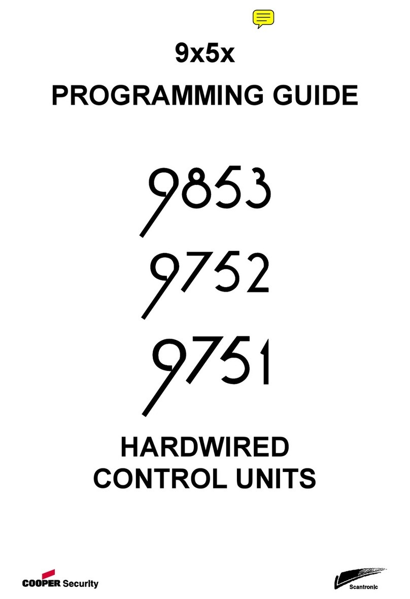
9x5x QUICK REFERENCE
PROGRAMMING GUIDE
HARDWIRED
CONTROL UNITS
9x5x Quick Reference Programming Guide
Page 2 497326, Issue 6
9853, 9752, 9751 Hardwired Control Unit Quick Reference Programming Guide
This document applies to control panels using software version 5.x.x.
© Cooper Security Ltd. 2009
Every effort has been made to ensure that the contents of this book are correct. However, neither the authors nor Cooper Security
Limited accept any liability for loss or damage caused or alleged to be caused directly or indirectly by this book. The contents of this book
are subject to change without notice.
Printed and published in the UK.
Cooper Security Ltd.
Security House
Vantage Point Business Village
Mitcheldean
Gloucestershire
GL17 0SZ
www.coopersecurity.co.uk
Product Support (UK) Tel: +44 (0)1594 541979
Available between: 08:15 to 12:30 and 13:00 to 17:00 Monday to Friday
Product Support Fax: +44 (0)1594 545401
Part Number 497326 Issue 5
Declarations of conformance to standards can be obtained from our Web site, www.coopersecurity.co.uk
9x5x Quick Reference Programming Guide
497326, Issue 6 Page 3
The cross-references shown in this guide refer to Issue 3b of the 9x5x Programming Guide (part number 497096).
Command Key in:
0 Country PTT Defaults (page 7) 0yny
n = Country:
0 = UK Y
1 = Italy (I)
2 = Spain (EE)
3 = Portugal (P)
4 = Netherlands (NL)
5 = France (FR)
6 = Belgium (B)
7 = Germany (D)
8 = Switzerland (CH)
9 = Austria (A)
X1 = Ireland (IRL)
X2 = OEM 1
X3 = OEM 2
X4 = Finland (FI)
X5 = Norway (N)
X6 = Denmark (DK)
X7 = Sweden (S)
Note: Executing this command loads all
defaults for the selected country.
01–X40 Zone Programming (page 7) nnyyab
nn = Zone number:
01 to 24 for 9751
01 to 32 for 9752
01 to 40 for 9853
Note:
For zones 1 to 16, key in "01" to "16"
For zones 17 to 40, key in "X17" to
"X40"
a = Zone type, one of:
00 = NU (Not Used)
01 = PA (Panic Alarm)
02 = FR (Fire)
03 = NA (Normal Alarm)
04 = 24 (24-hour)
05 = FE (Final Exit) see X7 below
06 = ER (Entry Route) see X7 below
07 = SA (Shock Analyser) see X7 below
08 = TC (Technical Alarm)
09 = KB (Keybox)
10 = SD (Smoke Detector)
11 = KM (Keyswitch Momentary)
12 = KF (Keyswitch Fixed)
13 = AM (Anti-Mask)
14 = FB (Forbikobler) see X7 below
15 = AC (AC Fail)
16 = LB (Low Battery)
17 = BF (Battery Fault)
18 = PF (Power Output Fault)
19 = FL (Fault)
Command Key in:
b = Zone attributes, any of:
X1 = C (Chime)
X2 = S (14-day Soak Test)
X3 = D (Double Knock)
X4 = O (Omit Allowed)
X5 = m (Masking)
X7 = 1–6 or 1–4
For zone type 07, shock analyser
sensitivity: 1 (low) to 6 (high)
For zone types 05, 06 and 14,
entry timer number: 1 to 4 (see
Commands 201–4 on page 66)
A = a (armed in Level/Partition A)
B = b (armed in Level/Partition B)
C = c (armed in Level/Partition C)
D = d (armed in Level/Partition D)
Default zone types for a
single system:
Default zone types in a
partitioned system:
Z01=FE abcd 1 Z01=FEa 1
Z02=ER abcd 1 Z02=ERa 1
Z03-Z07=NA abcd Z03-07=NA a
Z08=PA abcd Z08=PA a
Z09-Z40=NU a Z09-Z40=NU
Example: To set Zone 17 as a Normal
Alarm, active in Level B and with Omit
Allowed. Key in:
X17yy Zone Number
03 Normal Alarm
B Active in Level B
X4 Omit Allowed
yto store the value of the Command
20 Change Engineer Code (page 13) 20ynnnny
ggggy
nnnn = New Engineer Code (Code) 7890
gggg = New Guard Code (Guard)
Note: The Guard Code is available only
if enabled with Command 181.
21 Zone Configuration (page 14) 21yny
9751/2:
n = 0 Closed circuit tamper (CC+ComA/T)†
Y
1 Fully supervised loop (FSL 2K2/4K7)†
9853:
n = 0 Closed circuit 4 wire (CC 4 Wire)†
Y
1 End of line resistor (EOL 2K2)†
2 Fully supervised loop (FSL 2K2/4K7)‡
3 8 FSL plus 4 expanders (FSL + EXP)†
†Ensure first expander addressed as “1”.
‡Ensure first expander addressed as “2”.
22 Loudspeaker Chime (page 14) 22yny
n= Loudspeaker Chime volume
(In a partitioned system, this command
is available only for Partition A)
0 Off ( keypad only)
1 (minimum) to 9 (maximum) 5
9x5x Quick Reference Programming Guide
Page 4 497326, Issue 6
Command Key in:
23 Remote Reset Enable (page 15) 23yny
n = 0 Off
Y
1 On
Note: Set Command 33 to Option 1
24 Show Control Unit Account Name
(page 15)
24y
(displays name downloaded by ARC)
Press Xto return to installer mode
25 Internal Sounder Delay and Duration
(page 15)
25yny
n = 0 LS Timed (follows external sounder)
Y
1 LS Cont (continuous)
26 Internal Sounder Delay on Entry
(page 15)
26yny
n = 0 Bell Delay Off
1 Bell Delay On
Y
Note: Sounder delay is available only if:
Alarm Abort is Off (Command 36)
Bell Delay is not zero (Command 41) – not default
Alarm Confirm is Off (Command 89) – not default
27 Exit Fault External Sounder (page 15) 27yny
n = 0 Internal
Y
1 Local
28 Status Display (page 16) 28yny
n = 0 Status Continuous (always visible)
1 Status Timed (visible for 30s after an
event)
Y
29 Entry Alarm Delay Time (page 16) 29yny
n = 0 Delay Off
Y
1 Delay On
30 PA Response (page 16) 30yny
n = 0 PA response audible
Y
1 PA response silent
31 Zone Tamper User/Engineer Reset
(page 17)
31yny
n = 0 User reset after zone tamper
Y
1 Engineer reset after zone tamper
32 Keypads and Partitions (page 17) 32ynnnny
n = A Assign keypad to Partition A
B Assign keypad to Partition B
C Assign keypad to Partition C
D Assign keypad to Partition D
Note: Each keypad can be assigned to
any or all partitions. The default is for all
keypads to belong to all partitions.
33 System User/Engineer Reset
(page 18)
33yny
n = 0 User can reset the system
Y
1 Engineer must reset the system
34 PA User/Engineer Reset (page 18) 34yny
n = 0 User reset after PA
Y
1 Engineer reset after PA
35 First Circuit Lockout (page 18) 35yny
n = 0 Lockout first circuit to activate
Y
1 Rearm first circuit to activate
36 Alarm Abort (page 18) 36yny
n = 0 User cannot abort a false alarm
Y
1 User can abort a false alarm
Command Key in:
37 Daytime Tamper Communication
(page 19)
37yny
n = 0 Internal sounder only Y
1 Communicate tamper to ARC
38 System Tamper User/Engineer Reset
(page 19)
38yny
n = 0 User reset after Tamper Alarm
1 Engineer reset after Tamper Alarm Y
39 Level/Partition A Exit Mode (page 19) 39yny
n = In a single system:
0 Timed (full tone on setting) Y
1 Terminated (terminated by button)
2 Final Door (last door has a detector)
3 Lock Set (terminated by lock switch)
In a partitioned system:
0 Timed full tone on setting Y
1 Terminated (terminated by button)
2 Final Door (last door has a detector)
3 Instant (no exit tone)
4 Silent (double "beep" after exit time)
5 Lock Set (terminated by lock switch)
40 System Auto Rearm (page 21) 40yny
n = 0 Rearm Never Y
1 Rearm=1 (once)
2 Rearm=2 (twice)
3 Rearm=3 (three times)
4 Rearm=Always
Note: C41 has no effect if C89 is set to 1 and any of the
following applies: C162 is set to 0, C161 is set to 0 or C47,
C63, C73 or C77 do not require communications.
41 Bell Delay (page 21) 41yny
n = 0 No delay Y
1 1.5 minutes
2 3 minutes
3 5 minutes
4 10 minutes
5 15 minutes
6 20 minutes
42 Bell Duration (page 22) 42yny
n = 1 1.5 minutes
2 3 minutes
3 5 minutes
4 10 minutes
5 15 minutes Y
6 20 minutes
43 This command has been replaced by
Command 201.
44 Level/Partition A Exit Time (page 22) 44yny
n = 1 10 seconds
2 20 seconds Y
3 30 seconds
4 45 seconds
5 60 seconds
6 120 seconds
45 Entry/Exit Tone Volume (page 22)
(In a partitioned system, this command
is available only for Partition A)
45yny
n = 0 No Entry/Exit tone from sounder
n EE tone volume (1=low, 9=max) 5
9x5x Quick Reference Programming Guide
497326, Issue 6 Page 5
Command Key in:
46 Tamper Alarm Response – single
system only (page 23)
46yny
n = 0 Internal sounders only
1 Keypad sounders only
2 Internal and keypad sounders
Y
47 Partition A Alarm Response –
partitioned system only (page 23)
47yny
n = 0 Keypad sounders only
Y
1 Local (all sounders, no comms)
2 Full (all sounders and comms)
48 Lockout Keypads During Entry
(page 23)
48yny
n = 0 Off
Y
1 On
Note: In a partitioned system, option 1
shows abcd to indicate that the setting
affects all partitions. You cannot change
the partitions affected.
49 Duress Code (page 24)
n = 0 Disabled
Y
1 Enabled
50 CSID Code (page 24) 50ynnnny
nnnn = Central Station ID for remote reset none
51 Set Time and Date (page 25) 51yddy
mmyyyy
hhymmy
dd Day of the month (01–31)
mm Month of the year (01–12)
yy Year (00–99)
hh Hour of the day (01–23)
mm Minute of the hour (01–59)
52 Omit Alarm (page 25) 52yny
n = 0 Alarm contacts only
Y
1 Alarm and tamper contacts
53 Abort User/Engineer Reset (page 25) 53yny
n = 0 Use option selected in Command
33
Y
1 User reset after an aborted alarm
54 Supervision Time (page 25) 54yny
n = 0 Supervision time slow
1 Supervision time fast
Y
55 Supervision Response (page 26) 55yny
n = 0 Supervision response tamper
Y
1 Supervision response alarm
2 Supervision response fault
3 Supervision response silent
56 Number of Digits in Access Codes
(page 26)
56yny
n = 0 Four-digit codes
(default user = 1234)
Y
1 Six-digit codes
(default user = 123456,
default installer = 567890)
57 Battery Load Test – not 9751
(page 27)
57yny
n = 0 Disabled
Y
1 Enabled
58 Day Tamper User/Engineer Reset
(page 28)
58yny
n = 0 User Reset
Y
1 Installer Reset
Command Key in:
59 External Sounder Tamper (page 28) 59yny
n = 0 Negative voltage tamper return
Y
1 End of line 2k2 resistor
60 Level/Partition B Final Exit Operation
– single system only (page 28)
60yny
n = 0 B=FE = FE (Final Exit)
Y
1 B=FE = NA (Normal Alarm)
61 Level/Partition B Entry Route
Operation – single system only
(page 29)
61yny
n = 0 B=ER = ER (Entry Route)
Y
1 B=ER = FE (Start entry timer)
62 Level/Partition B Exit Mode (page 29) 62yny
n = In a single system:
0 Timed low tone on setting
Y
1 Instant (no exit tone)
2 Silent (double "beep" after exit time)
3 Sets exit mode the same as Level A
In a partitioned system:
0 Timed full tone on setting
Y
1 Terminated (terminated by button)
2 Final Door (last door has a detector)
3 Instant (no exit tone)
4 Silent (double "beep" after exit time)
5 Lock Set (terminated by lock switch)
63 Level/Partition B Alarm Response
(page 30)
63yny
n = In a single system:
0 Keypad sounders only
1 Internal and keypad sounders
Y
2 Local (all sounders, no comms)
3 Full (all sounders and comms)
In a partitioned system:
0 Keypad sounders only
Y
1 Local (all sounders, no comms)
2 Full (all sounders and comms)
64 This command has been replaced by
Command 202.
65 Level/Partition B Exit Time (page 30) 65yny
n = 1 10 seconds
2 20 seconds
Y
3 30 seconds
4 45 seconds
5 60 seconds
6 120 seconds
66 Forbikobler Keypads and Partitions –
partitioned system only (page 30)
66ynnnny
n = A Assign keypad to Partition A
B Assign keypad to Partition B
C Assign keypad to Partition C
D Assign keypad to Partition D
Note: Each keypad can be assigned to
any or all partitions. The default is for all
keypads to belong to all partitions.
67 Forbikobler Approved (page 31) 67yny
n = 0 Frb=Non-Appr (not approved)
1 Frb=Approved (approved)
Y
9x5x Quick Reference Programming Guide
Page 6 497326, Issue 6
Command Key in:
68 Forbikobler Door Timer (page 31) 68yny
n = 0 2 seconds
1 3 seconds
2 4 seconds
3 5 seconds
Y
4 10 seconds
5 20 seconds
6 30 seconds
7 60 seconds
8 120 seconds
9 255 seconds
69 Forbikobler Door Locking (page 31) 69yny
n = 0 Lock Timed
Y
1 Lock Toggled
70 Level/Partition C Final Exit Operation
– single system only (page 31)
70yny
n = 0 C=FE = FE (Final Exit)
Y
1 C=FE = NA (Normal Alarm)
71 Level/Partition C Entry Route
Operation – single system only
(page 32)
71yny
n = 0 C=ER = ER (Entry Route)
Y
1 C=ER = FE (Start entry timer)
72 Level/Partition C Exit Mode (page 32) 72yny
n = In a single system:
0 Timed low tone on setting
Y
1 Instant (no exit tone)
2 Silent (double "beep" after exit time)
3 Sets exit mode the same as Level A
In a partitioned system:
0 Timed full tone on setting
Y
1 Terminated (terminated by button)
2 Final Door (last door has a detector)
3 Instant (no exit tone)
4 Silent (double "beep" after exit time)
5 Lock Set (terminated by lock switch)
73 Level/Partition C Alarm Response
(page 33)
73yny
n = In a single system:
0 Keypad sounders only
1 Internal and keypad sounders
Y
2 Local (all sounders, no comms)
3 Full (all sounders and comms)
In a partitioned system:
0 Keypad sounders only
Y
1 Local (all sounders, no comms)
2 Full (all sounders and comms)
74 This command has been replaced by
Command 203.
75 Level/Partition C Exit Time (page 33) 75yny
n = 1 10 seconds
2 20 seconds
Y
3 30 seconds
4 45 seconds
5 60 seconds
6 120 seconds
Command Key in:
76 Level/Partition D Exit Mode (page 34) 76yny
n = In a single system:
0 Timed low tone on setting Y
1 Instant (no exit tone)
2 Silent (double "beep" after exit time)
3 Sets exit mode the same as Level A
In a partitioned system:
0 Timed full tone on setting Y
1 Terminated (terminated by button)
2 Final Door (last door has a detector)
3 Instant (no exit tone)
4 Silent (double "beep" after exit time)
5 Lock Set (terminated by lock switch)
77 Level/Partition D Alarm Response
(page 35)
77yny
n = In a single system:
0 Keypad sounders only
1 Internal and keypad sounders Y
2 Local (all sounders, no comms)
3 Full (all sounders and comms)
In a partitioned system:
0 Keypad sounders only
1 Local (all sounders, no comms)
2 Full (all sounders and comms) Y
78 This command has been replaced by
Command 204.
79 Level/Partition D Exit Time (page 35) 79yny
n = 1 10 seconds
2 20 seconds Y
3 30 seconds
4 45 seconds
5 60 seconds
6 120 seconds
80 Forbikobler Chime (page 36) 80yny
n = 0 Bell push does not operate
sounders
Y
1 Bell push operates sounders
9x5x Quick Reference Programming Guide
497326, Issue 6 Page 7
Command Key in:
81 Output 1 Type (page 36) 81ynny
nn = Where n is one of:
In a single or partitioned system:
00 Bell
Y
01 EE Follow
02 Armed Lamp
03 Set Latch
04 Shock Sensor Reset
05 Walk Test
06 Ready Lamp
07 24-hour Alarm
08 Strobe
09 Smoke Sensor Reset
10 French Siren Test
11 Strobe Set (any partition)
12 Pulse Set 1
13 Pulse Unset 1
14 Alarm Confirmation
15 Set Complete
16 Unset Complete
17 System Alarm
In a partitioned system:
18 Bell Partition A
19 Bell Partition B
20 Bell Partition C
21 Bell Partition D
22 Strobe Set Partition A
23 Strobe Set Partition B
24 Strobe Set Partition C
25 Strobe Set Partition D
26 Pulse Set 1
27 Pulse Set 2
28 Pulse Set 3
29 Pulse Set 4
30 Pulse Unset 1
31 Pulse Unset 2
32 Pulse Unset 3
33 Pulse Unset 4
34 Fire
35 PA
36 Set Fail
37 General Fault
38 All Fault
82 Output 2 Type (page 36) 82ynny
nn = See Command 81 for a list of options.
Default is 08 Strobe
83 Output 3 Type (page 36) 83ynny
nn = See Command 81 for a list of options.
Default is 03 Set Latch
84 Output 4 Type (page 36) – 9853 only 84ynny
nn = See Command 81 for a list of options.
Default is 04 Shock Sensor Reset
85 Burg Communication Rearm
(page 38)
85yny
n = 0 Latched
Y
1 Rearm
Command Key in:
86 This command has been replaced by
the changed command 29
87 Keypad Dual Key Alarms (page 39) 87ynynyny
Use A or B keys to scroll through PA, FI and MD.
n = 0 Off
Y
1 On (PA enabled)
0 Off
Y
1 On (Fire enabled)
0 Off
Y
1 On (Medical enabled)
Note: Setting PA to option 1 also
enables a PA from keyswitches (9928).
88 Anti-Mask Mode (page 39) 88yny
n = 0 Masking (4.4kΩand 9.1kΩ)
Y
1 Masking (9.1kΩ) and Fault (4.4kΩ)
89 Alarm Confirmation (page 39) 89yny
n = 0 None (default outside the UK) (Y)
1 UK (DD 243) (default in the UK) (Y)
2 Two zones
90 Event Log (page 69) 90yny
Shows the most recent event in the log
n = 0 Print log (9853 only)
1 View earlier events
3 View later events
4 First event
6 Last event
7 Toggle printer on/off (9853 only)
8 Print configuration (9853 only)
XCancel viewing
yToggles time/date display
91 Test Normal Outputs 1 to 8 (page 74) 91y
Keys 1 to 8 operate outputs 1 to 8 (1 to
3 for 975x), press Xor yto end test
92 Test Plug-by Outputs 1 to 12
(page 74)
92y
Keys 1 to C operate outputs 1 to 12 (1
to 8 for 975x), key 0 initiates an ATS
test, press Xor yto end test
93 This command has been replaced by
the changed command 91
94 Test Internal Sounder (page 73) 94y
Internal sounders operate, press Xor y
to end test
95 Test Keypad Sounder (page 73) 95y
Keypad sounders operate, press Xor y
to end test
96 This command has been replaced by
the changed command 91
97 Engineer Walk Test (page 74) 97y
Zn indication and Chime operate when
circuit open
XEnd Walk Test
98 Load Full Defaults (page 40) 98y1yny
n = 0 Single system
Y
1 Partitioned system
99 Leave Installer Mode (page 41) 99yy
100 This command is not used.
9x5x Quick Reference Programming Guide
Page 8 497326, Issue 6
Command Key in:
C101-158 are for programming communications.
101 Call Mode (page 41) 101yny
n = 0 Disabled
Y
1 Single
2 Alternate
3 Dual
102 Communication Fault Timeout 102yny
n = 0 60 seconds
1 120 seconds
2 240 seconds
Y
3 480 seconds
103 Reporting Type (page 42) 103yny
n = 0 Fast format
Y
1 Contact ID
2 SIA I
3 SIA II
4 SIA 3
5 Extended SIA 3
6 Home "beep"
104 This command is not used.
105 Static Test Call (page 43) 105yN nny
N nn = 00 Static off
Y
A nn = Static call daily at nn hours, 01 to 24
B nn = Static call monthly on day nn, 01 to 28
C nn = Static call every nn hours, 01 to 24
D nn = Static call every nn days, 01 to 28
106 Line Fault Response (page 44) 106yny
n = 0 Disabled
1 Audible
Y
2 Silent
107 Dial Tone Delay (page 44) 107ynny
nn = delay in seconds, 07 to 20
default 07
Note: Available in software version 4.03.xx onwards.
108 Dynamic Test Call (page 45) 108yny
n = 0 Dynamic test calls disabled
Y
1 Dynamic test calls enabled
109 Three-way Calling – UK only
(page 45)
109yny
n = 0 Three-way calling disabled
Y
1 Three-way calling enabled
110 Download Mode (page 45) 110yny
n = 0 Local PC (not 9751)
Y
1 Remote PC
Note: 110yon 9751 selects Remote,
with no option available.
111 Modem Speed – 9853 only (page 46) 111yny
n = 0 Auto
1 300 baud
Y
112 Rings to Answer – Downloading
option (page 46)
112yny
n = 0 3 rings
1 5 rings
Y
2 7 rings
3 10 rings
4 15 rings
5 255 rings
Command Key in:
113 Answer on One Ring – Downloading
option (page 46)
113yny
n = 0 One ring off Y
1 One ring on
114 Access Mode (page 47) 114yny
n = 0 Callback off (Attended) Y
1 Callback on (Secure Callback)
2 Callback any (Unattended)
115 Communicator Tel No 1 (page 47) 115yn..ny
n...n = Maximum 31 digits
116 Communicator Tel No 2 (page 47) 116yn..ny
n...n = Maximum 31 digits
117 Account Number (page 48) 117yn..ny
n...n = Maximum 6 digits
(press C/D to move right/left)
Note: In a partitioned system, you can
set a number for each partition.
118 Downloader Tel No 1 (page 48) 118yn..ny
n...n = Maximum 31 digits
119 Downloader Tel No 2 (page 48) 119yn..ny
n...n = Maximum 31 digits
120 Enable Downldr Tel No 3 (page 48) 120yny
n = 0 Downloader Tel No 3 Off
Y
1 Downloader Tel No 3 On
121 This command has been replaced by
commands 191-198.
122 Communication Acknowledge –
Ireland only (page 49)
122yny
n = 0 Off
Y
1 On
Note: Command 122 is available only if
Command 0 is set to X1 (Ireland).
123 Report Restores (page 49) 123yny
n = 0 Restores not reported
Y
1 Restores reported
124 Reverse Open/Closed (page 49) 124yny
n = 0 Off (disabled)
Y
1 On (reverse Channel 4)
Note: Normally set to option 1 in France
125 No Close Signal (page 49) 125yny
n = 0 Off
Y
1 On: no close signal is sent if more
than one circuit is omitted
126 Select Language (page 50) 126ynny
nn = 0 = English
Y
1 = Italian
2 = Espanol
3 = Port
4 = Nederl
5 = Francai
6 = Deutsch
7 = Norsk
8 = Svenska
9 = Dansk
X1 = Suomi
127 This command is not used.
9x5x Quick Reference Programming Guide
497326, Issue 6 Page 9
Command Key in:
128 This command has been replaced by
command 55.
129 Telecommand Requires Entry for
Unset (page 50)
129yny
n = 0 External Unset Off Y
1 External Unset On
130 This command is not used.
131 SIA Report Mode (page 51) 131yny
n = 0 Basic Y
1 Summary
2 Intermediate
3 Full
132 Send Tampers as Burglary (page 51) 132yny
n = 0 Send standard SIA messages Y
1 Send modified SIA messages
133 Do not Send SIA Restores (page 54) 133yny
n = 0 Do not send SIA restores Y
1 Send SIA restores
134 AC Fail User/Installer Reset (page 54) 134yny
n = 0 No Reset Required Y
1 User Reset
2 Installer Reset
135 Line Fault User/Installer Reset
(page 54)
135yny
n = 0 No Reset Required Y
1 User Reset
2 Installer Reset
136 Anti-Mask User/Installer Reset
(page 55)
136yny
n = 0 User Reset Y
1 Installer Reset
137 AC Fail Override (page 55) 137yny
n = 0 Never
1 Inactive
2 Any Y
138 Line Fault Override (page 55) 138yny
n = 0 Never
1 If Only 1 Fault
2 Any Y
139 Fault User/Installer Reset (page 56) 139yny
n = 0 User Reset Y
1 Installer Reset
140 Fault Override (page 56) 140yny
n = 0 Never Y
1 Inactive
141 Alert Tone On/Off (page 57) 141yny
n = 0 Disabled
1 Enabled Y
142 This command is not used.
143 Contact ID Report Restores (page 57) 143yny
n = 0 Mode Basic
1 Mode Basic + Restore Y
144-50 These commands are not used.
Command Key in:
151 Plug-by Communications Output 1
(page 57)
151ynny
nn = 00 Not Used
01 Fire
Y
02 PA (not sent in Duress, see option 41 below).
03 Burglar
04 Open/Closed
05 Alarm Abort
06 Technical Alarm
07 Alarm Confirmation
08 RF Low Battery
09 RF Supervision Loss
10 RF Jamming
11 AC Fail (15-18 mins delay before transmission)
12 Tamper Alarm (see command 37 to enable)
13 Open
14 Close
15 Zone Omitted
16 Medical
17 Keybox
18 Anti-Mask
19 Smoke Detector
20 Comms Acknowledge
21 Battery Fault
22 System Alarm
In a partitioned system:
23 Alarm Partition A
24 Alarm Partition B
25 Alarm Partition C
26 Alarm Partition D
27 Not used
28 Not used
29 Not used
30 Pulse Set 1
31 Pulse Set 2
32 Pulse Set 3
33 Pulse Set 4
34 Pulse Unset 1
35 Pulse Unset 2
36 Pulse Unset 3
37 Pulse Unset 4
38 Set Fail
39 General Fault
40 All Fault
41 Duress (see command 49 to enable)
42 ATS Test
9x5x Quick Reference Programming Guide
Page 10 497326, Issue 6
Command Key in:
152 Plug-by Communications Output 2
(page 57)
152ynny
n = See Command 151 for a list of options.
Default is 02 PA
Y
153 Plug-by Communications Output 3
(page 57)
153ynny
n = See Command 151 for a list of options.
Default is 03 Burglar
Y
154 Plug-by Communications Output 4
(page 57)
154ynny
n = See Command 151 for a list of options.
Default is 04 Open/Close
Y
155 Plug-by Communications Output 5
(page 57)
155ynny
n = See Command 151 for a list of options.
Default is 15 Zone Omitted
Y
156 Plug-by Communications Output 6
(page 57)
156ynny
n = See Command 151 for a list of options.
Default is 05 Alarm Abort
Y
157 Plug-by Communications Output 7
(page 57)
157ynny
n = See Command 151 for a list of options.
Default is 07 Alarm Confirm
Y
158 Plug-by Communications Output 8
(page 57)
158ynny
n = See Command 151 for a list of options.
Default is 06 Technical Alarm
Y
159 Invert Plug-by Outputs (page 59) 159ynny
n = 0 Off (do not invert logic)
Y
1 On (invert logic)
C160 is valid only if C89 is set to option 1. C161-164 are
valid if C89 is set to option 1 or 2.
160 Confirmed Alarm Timer (page 59) 160ynnny
nnn = a time from 001 to 999 minutes 030 minutes
161 Internal Sounder (page 60) 161yny
n = 0 Sounder on Unconfirmed Alarm
Y
1 Sounder on Confirmed Alarm only
162 External Sounder (page 60) 162yny
n = 0 Sounder on Unconfirmed Alarm
Y
1 Sounder on Confirmed Alarm only
163 Confirmed Alarm during Entry
(page 60)
163yny
n = 0 Never (no zones)
Y
1 One zone
2 Two zones
164 User/Engineer Reset after Confirmed
Alarm (page 61)
164yny
n = 0 User/Engineer
Y
1 User/User
2 Engineer/Engineer
165-9 These commands are not used.
Command Key in:
170 Pulse Set 1 to 4 Duration (page 61) 170y
nnynny
nnynny
nn = 00 to 12 seconds 01 seconds
171 Pulse Set Allocation (page 61) 171yny
nynyny
n = A Level/Partition A abcd
B Level/Partition B
C Level/Partition C
D Level/Partition D
172 Pulse Unset 1 to 4 Duration (page 61) 172y
nnynny
nnynny
nn = 00 to 12 seconds 01 seconds
173 Pulse Unset Allocation (page 61) 173yny
nynyny
n = A Level/Partition A abcd
B Level/Partition B
C Level/Partition C
D Level/Partition D
174 Fire Pulse Unset (page 61) 174yny
nynyny
n = 0 Off
1 On
Y
175 PA Pulse Unset 1 to 4 (page 61) 175yny
nynyny
n = 0 Off
1 On
Y
176-9 These commands are not used.
180 Print Log – 9853 only (page 63) 180yny
n = 0 Off
Y
1 On
181 Enable Guard Code (page 63) 181yny
n = 0 Off
Y
1 On
182 Set Final Exit Settling Time (page 63) 182yny
n = 07 7 seconds
Y
08 8 seconds
09 9 seconds
10 10 seconds
11 11 seconds
12 12 seconds
183 Set Display Line 2 (page 63) 183yn..ny
n...n = Maximum 16 digits
(press C/D to move right/left)
<model_no>
Note: This is displayed in user mode.
Its display in installer mode is toggled
by Command 90.
184 Pulsed External Sounder for Fire
(page 64)
184yny
n = 0 Off
Y
1 On
185 Keyswitch Auto Reset (page 64) 185yny
n = 0 Off
Y
1 On
186 Set Number of Home "Beep" Calls
(page 64)
186ynny
nn = 01 to 15 times 02 times
187-90 These commands are not used.
9x5x Quick Reference Programming Guide
497326, Issue 6 Page 11
Command Key in:
C191-198 are for programming communications.
191 Fast Format Channel 1 (page 65) 191ynny
nn = 00 Not Used
01 Fire Y
02 PA (not sent in Duress, see option 41 below)
03 Burglar
04 Open/Closed
05 Alarm Abort
06 Technical Alarm
07 Alarm Confirmation
08 RF Low Battery
09 RF Supervision Loss
10 RF Jamming
11 AC Fail (15-18 mins delay before transmission)
12 Tamper Alarm (see command 37 to enable)
13 Open
14 Close
15 Zone Omitted
16 Medical
17 Keybox
18 Anti-Mask
19 Smoke Detector
20 Comms Acknowledge
21 Battery Fault
22 System Alarm
In a partitioned system:
23 Alarm Partition A
24 Alarm Partition B
25 Alarm Partition C
26 Alarm Partition D
27 Not used
28 Not used
29 Not used
30 Pulse Set 1
31 Pulse Set 2
32 Pulse Set 3
33 Pulse Set 4
34 Pulse Unset 1
35 Pulse Unset 2
36 Pulse Unset 3
37 Pulse Unset 4
38 Set Fail
39 General Fault
40 All Fault
41 Duress (see command 49 to enable)
192 Fast Format Channel 2 (page 65) 192ynny
n = See Command 191 for a list of options.
Default is 02 PA Y
193 Fast Format Channel 3 (page 65) 193ynny
n = See Command 191 for a list of options.
Default is 03 Burglar Y
194 Fast Format Channel 4 (page 65) 194ynny
n = See Command 191 for a list of options.
Default is 04 Open/Close Y
Command Key in:
195 Fast Format Channel 5 (page 65) 195ynny
n = See Command 191 for a list of options.
Default is 15 Zone Omitted
Y
196 Fast Format Channel 6 (page 65) 196ynny
n = See Command 191 for a list of options.
Default is 05 Alarm Abort
Y
197 Fast Format Channel 7 (page 65) 197ynny
n = See Command 191 for a list of options.
Default is 07 Alarm Confirmation
Y
198 Fast Format Channel 8 (page 65) 198ynny
n = See Command 191 for a list of options.
Default is 06 Technical Alarm
Y
199 Display Zone Circuit Resistance
(page 75)
199y
= Use the A and C keys to step through
circuits or type in two-digit zone No..
200 Forbikobler Entry Timer (page 66) 200yny
nynyny
n = 1 Entry Timer 1
Y
2 Entry Timer 2
3 Entry Timer 3
4 Entry Timer 4
201 Entry Timer 1 (page 66) 201yny
n = 1 10 seconds
2 20 seconds
Y
3 30 seconds
4 45 seconds
5 60 seconds
6 120 seconds
202 Entry Timer 2 (page 66) 202yny
n = 1 10 seconds
2 20 seconds
Y
3 30 seconds
4 45 seconds
5 60 seconds
6 120 seconds
203 Entry Timer 3 (page 66) 203yny
n = 1 10 seconds
2 20 seconds
Y
3 30 seconds
4 45 seconds
5 60 seconds
6 120 seconds
204 Entry Timer 4 (page 66) 204yny
n = 1 10 seconds
2 20 seconds
Y
3 30 seconds
4 45 seconds
5 60 seconds
6 120 seconds
9x5x Quick Reference Programming Guide
Page 12 497326, Issue 6
Command Key in:
C211-218: programming communications (9853 only).
211 Plug-by Communications Output 9
(page 68) – 9853 only
211ynny
n = See Command 151 for a list of options.
Default is 11 AC Fail
Y
212 Plug-by Communications Output 10
(page 68) – 9853 only
212ynny
n = See Command 151 for a list of options.
Default is 21 Battery Fault
Y
213 Plug-by Communications Output 11
(page 68) – 9853 only
213ynny
n = See Command 151 for a list of options.
Default is 40 All Fault
Y
214 Plug-by Communications Output 12
(page 68) – 9853 only
214ynny
n = See Command 151 for a list of options.
Default is 12 Tamper Alarm
Y
215 Output 5 Type (page 68) – 9853 only 215ynny
n = See Command 81 for a list of options.
Default is 15 Set Complete
Y
216 Output 6 Type (page 68) – 9853 only 216ynny
n = See Command 81 for a list of options.
Default is 16 Unset Complete
Y
217 Output 7 Type (page 68) – 9853 only 217ynny
n = See Command 81 for a list of options.
Default is 38 All Fault
Y
218 Output 8 Type (page 68) – 9853 only 218ynny
n = See Command 81 for a list of options.
Default is 01 EE Follow
Y
991 Display Software Version (page 75) 991y
= Press Yto step through expanders and
see mains frequency.

Other manuals for Scantronic 9 5 Series

1

This manual suits for next models

3

Other Cooper Control Unit manuals

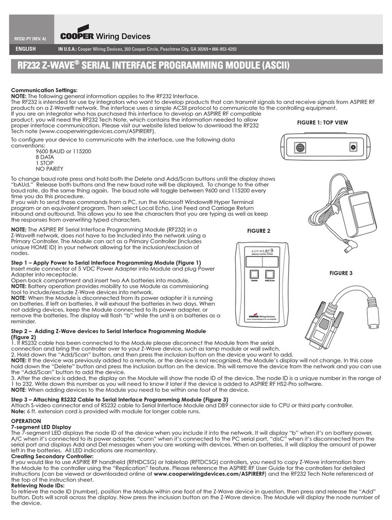
Cooper Z-WAVE RF232 User manual

Cooper

Cooper Z-WAVE RF232 User manual

Cooper Scantronic 770r User manual

Cooper

Cooper Scantronic 770r User manual

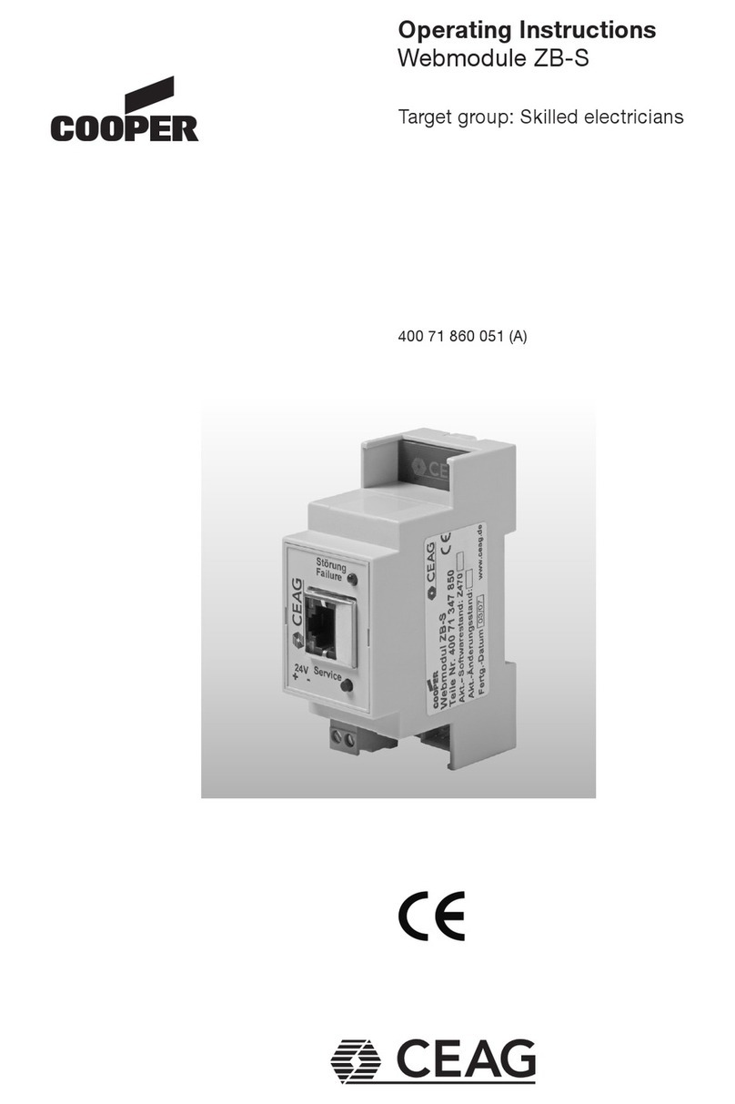
Cooper CEAG Webmodule ZB-S User manual

Cooper

Cooper CEAG Webmodule ZB-S User manual

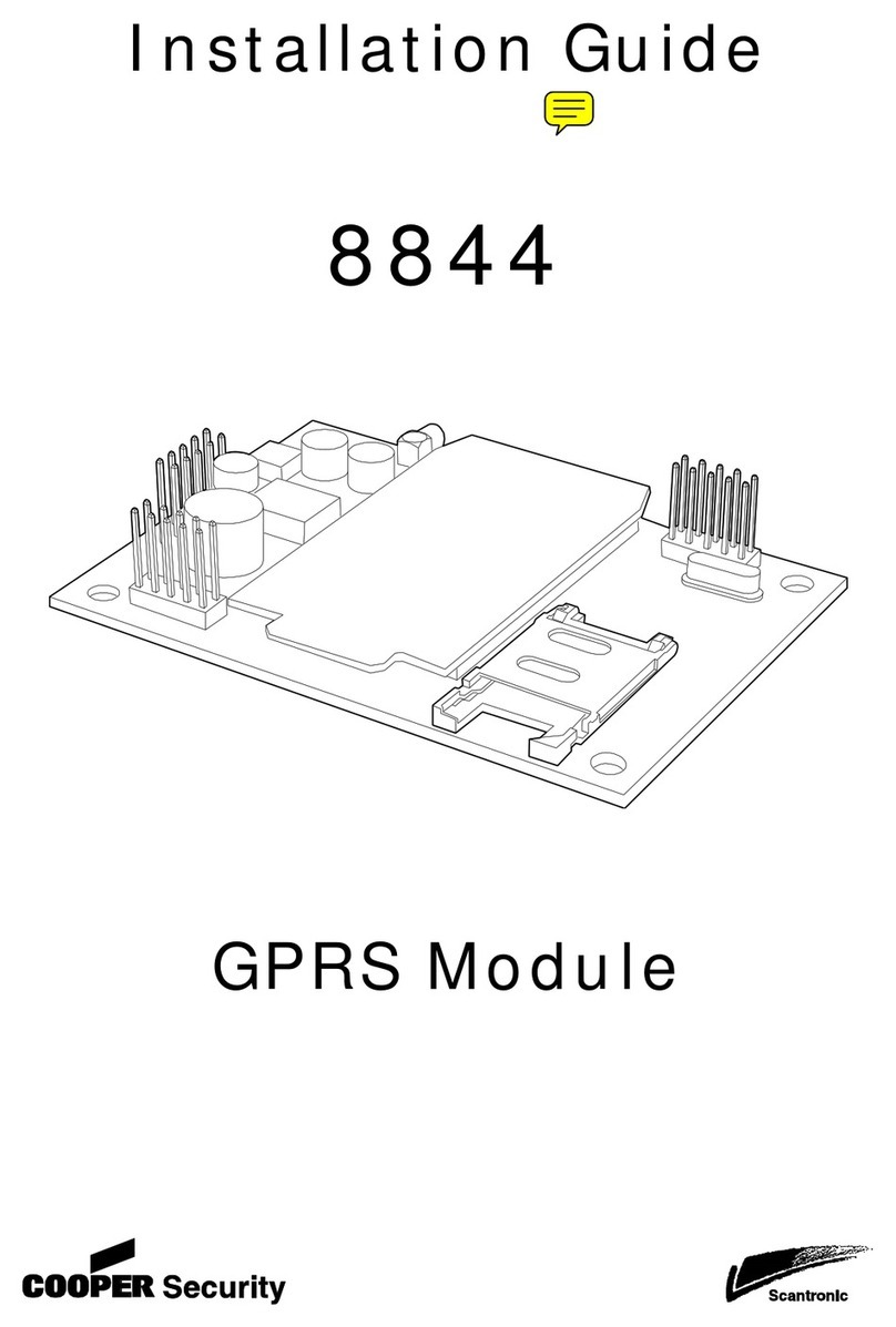
Cooper Scantronic 8844 User manual

Cooper

Cooper Scantronic 8844 User manual

Cooper S280-79-10 User manual

Cooper

Cooper S280-79-10 User manual

Cooper F6-PA-LS User manual

Cooper

Cooper F6-PA-LS User manual

Cooper Scantronic 9 5 Series Operating instructions

Cooper

Cooper Scantronic 9 5 Series Operating instructions

Cooper 9930 User manual

Cooper

Cooper 9930 User manual

Cooper Scantronic 95 User manual

Cooper

Cooper Scantronic 95 User manual

Cooper LCMD-10 User manual

Cooper

Cooper LCMD-10 User manual

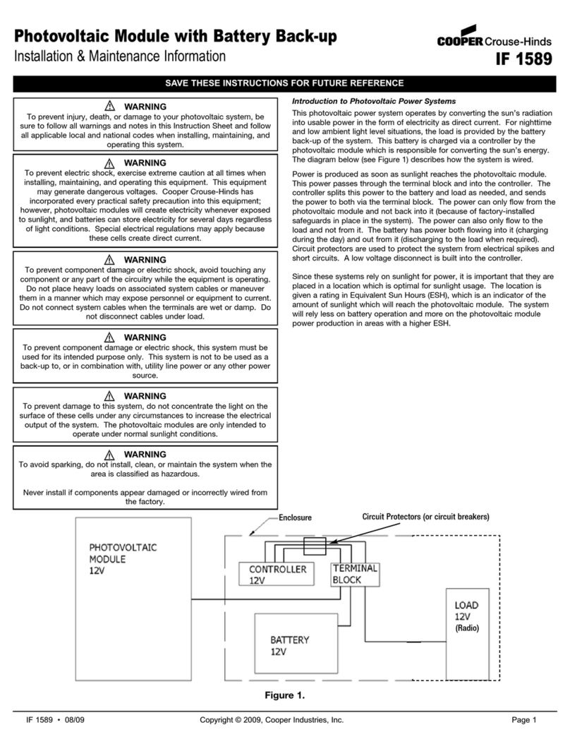
Cooper Crouse-Hinds IF 1589 Setup guide

Cooper

Cooper Crouse-Hinds IF 1589 Setup guide

Cooper Scantronic 65 User manual

Cooper

Cooper Scantronic 65 User manual

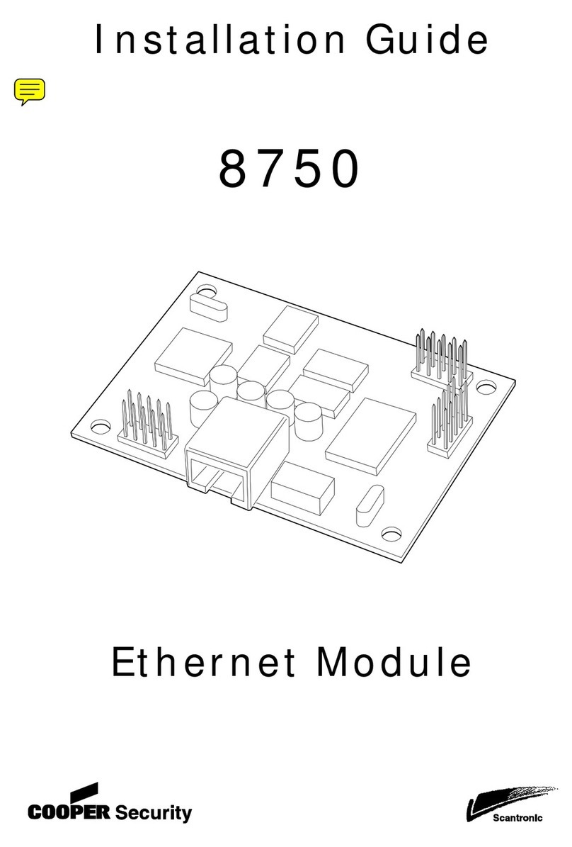
Cooper Scantronic 8750 User manual

Cooper

Cooper Scantronic 8750 User manual

Popular Control Unit manuals by other brands

GTC GTC-GG1H-72 W Series installation manual

GTC

GTC GTC-GG1H-72 W Series installation manual

SEA GATE 1 DG R2BF quick start

SEA

SEA GATE 1 DG R2BF quick start

M-system R7C-EC8A instruction manual

M-system

M-system R7C-EC8A instruction manual

TLV NF6 instruction manual

TLV

TLV NF6 instruction manual

DEMA CHEMASTER DM-813-LLL-1T instruction manual

DEMA

DEMA CHEMASTER DM-813-LLL-1T instruction manual

Milltronics airanger XPL plus instruction manual

Milltronics

Milltronics airanger XPL plus instruction manual

Dräger Evita V Series quick start guide

Dräger

Dräger Evita V Series quick start guide

Assa Abloy LCU9101IV manual

Assa Abloy

Assa Abloy LCU9101IV manual

Maker Factory ARDUINO MAKEVMA310 user manual

Maker Factory

Maker Factory ARDUINO MAKEVMA310 user manual

DFI SH960MD-CM236/QM170 user manual

DFI

DFI SH960MD-CM236/QM170 user manual

Honeywell CENTRALINE CLCM1H112 installation instructions

Honeywell

Honeywell CENTRALINE CLCM1H112 installation instructions

Kolver EDU2AE/FR 2.00 Operational manual

Kolver

Kolver EDU2AE/FR 2.00 Operational manual

System Sensor SC-6 Installation and maintenance instructions

System Sensor

System Sensor SC-6 Installation and maintenance instructions

Nice HSTS2 Instructions and warnings for installation and use

Nice

Nice HSTS2 Instructions and warnings for installation and use

Praher Plastics Aquastar Easy Replacement manual

Praher Plastics

Praher Plastics Aquastar Easy Replacement manual

Advantech SOM-5962 user manual

Advantech

Advantech SOM-5962 user manual

Rtelligent T60-IO user manual

Rtelligent

Rtelligent T60-IO user manual

Stone STWA070WT-01 Equipment manual

Stone

Stone STWA070WT-01 Equipment manual

manuals.online logo
manuals.online logoBrands
  • About & Mission
  • Contact us
  • Privacy Policy
  • Terms and Conditions

Copyright 2025 Manuals.Online. All Rights Reserved.