LCI Gooseneck Connect Installation instructions

1
lci1.com 574-537-8900 Rev: 01.19.21
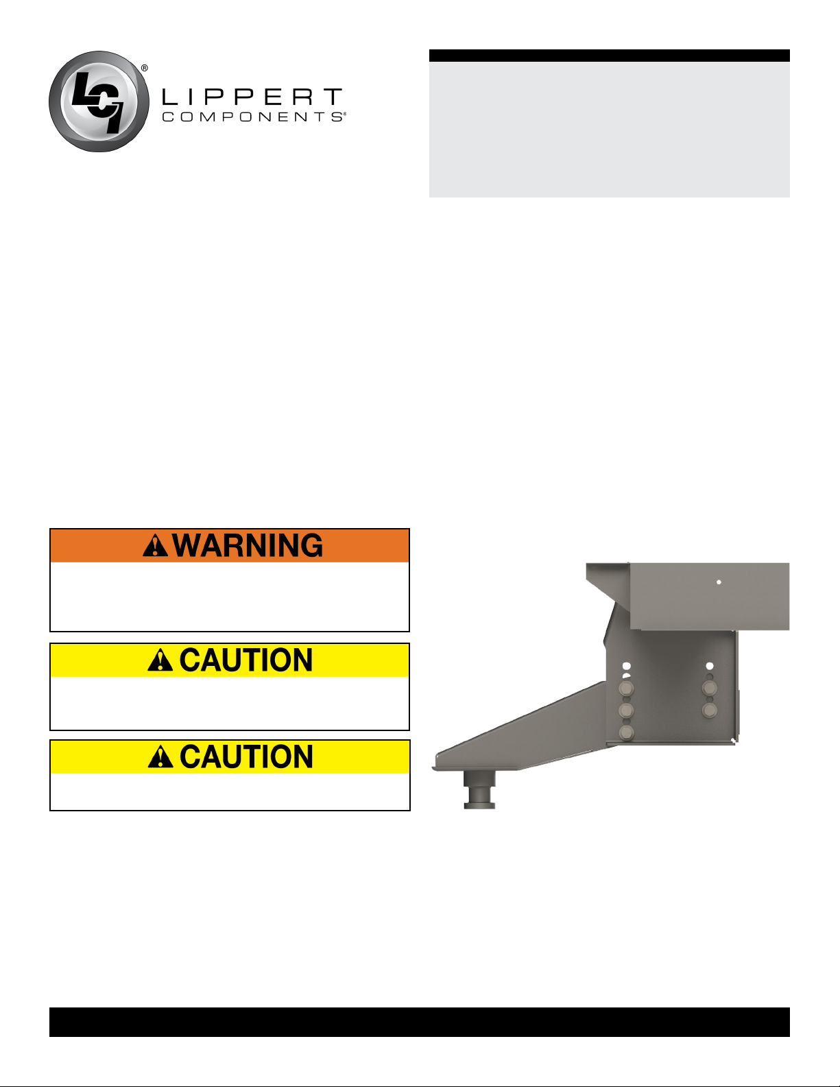
Gooseneck Connect™
21K Pin Box
Installation and Owner’s Manual
(For Aftermarket Applications)
CCD-003644
Table of Contents
Introduction ............................................ 2
Safety ................................................... 2
Parts List ................................................ 3
Resources Required ................................... 4
Preparation ............................................. 4
Removal of Factory Pin Box ........................... 4
Installation .............................................. 5
Install new pin box ..................................... 5
Operation ............................................... 6
Maintenance ............................................ 7
Notes .................................................. 7-8
Notes .................................................... 8
Gooseneck
Connect™
21K Pin Box
Installation and
Owner’s Manual
(For Aftermarket Applications)
Gooseneck Connect Pin Box KitGooseneck Connect Pin Box Kit
Part #Part # DescriptionDescription
2020043670
Gooseneck pin box kit to convert 21K Rhino
pin box to gooseneck pin box compatible.
Hardware included.

2
lci1.com 574-537-8900 Rev: 01.19.21
Gooseneck Connect™
21K Pin Box
Installation and Owner’s Manual
(For Aftermarket Applications)
CCD-003644
Introduction
The Gooseneck Connect pin box provides a safe and
LCI-approved method of converting a new Rhino pin box-
equipped trailer to a gooseneck pin box compatible with a
gooseneck hitch. The gooseneck pin box fits the new hole
pattern of the single header Space Saver Upper Deck.
Additional information about this product can be obtained
from lci1.com/support or by using the myLCI app.
Replacement kits can be ordered from https://store.lci1.
com/ or by using the myLCI app.
The myLCI app is available for free on iTunes®for iPhone®
and iPad®and also on Google Play™for Android™users.
iTunes ®, iPhone®, and iPad®are registered trademarks of
Apple Inc.
Google Play™and Android™are trademarks of Google Inc.
Images used in this document are for reference only when
assembling, installing and/or operating this product. Actual
appearance of provided and/or purchased parts and
assemblies may differ.
Safety
Read and understand all instructions before installing or
operating this product. Adhere to all safety labels. This
manual provides general instructions. Many variables can
change circumstances of instructions, i.e., the degree of
difficulty, operation and ability of the individual performing
the instructions. This manual cannot begin to plot out
instructions for every possibility, but provides the general
instructions, as necessary, for effectively interfacing with
the device, product or system. Failure to correctly follow
the provided instructions may result in death, serious
personal injury, severe product and/or property damage,
including voiding of the LCI limited warranty.
THE “WARNING” SYMBOL ABOVE IS A SIGN THAT
AN INSTALLATION PROCEDURE HAS A SAFETY
RISK INVOLVED AND MAY CAUSE DEATH, SERIOUS
PERSONAL INJURY OR SEVERE PRODUCT AND/
OR PROPERTY DAMAGE IF NOT PERFORMED
SAFELY WITHIN PARAMETERS SET FORTH IN THIS
MANUAL.
THE “CAUTION” SYMBOL ABOVE IS A SIGN THAT
A PROCEDURE HAS A RISK INVOLVED THAT MAY
CAUSE PERSONAL INJURY OR PROPERTY DAMAGE
IF NOT PERFORMED SAFELY AND WITHIN THE
PARAMETERS SET FORTH WITHIN THIS MANUAL.
THE TRAILER MUST BE SUPPORTED PER
MANUFACTURER’S RECOMMENDATIONS BEFORE
WORKING UNDERNEATH. FAILURE TO DO SO MAY
RESULT IN DEATH OR SERIOUS PERSONAL INJURY.
FAILURE TO CHECK AND FOLLOW TOW RATINGS
COULD RESULT IN TOW VEHICLE DAMAGE OR
TOW VEHICLE AND TRAILER SEPARATION WHILE
TOWING. TRAILER AND ITS CONTENTS MUST NOT
EXCEED TOW VEHICLE, HITCH AND/OR TRAILER
TOW R ATINGS.
FAILURE TO FOLLOW THESE INSTRUCTIONS MAY
RESULT IN DEATH OR SERIOUS INJURY.
MOVING PARTS CAN PINCH, CRUSH OR CUT. KEEP
CLEAR AND USE CAUTION.

3
lci1.com 574-537-8900 Rev: 01.19.21
Gooseneck Connect™
21K Pin Box
Installation and Owner’s Manual
(For Aftermarket Applications)
CCD-003644
Gooseneck Connect Kit #2020043670Gooseneck Connect Kit #2020043670
LetterLetter PNPN DescriptionDescription QtyQty
A 859275 Gooseneck pin box 1
B131619 Bolt, 5/8” - 11, Grade 5 10
C118130 Flat washer, 5/8” 10
D118166 Lock washer, 5/8” 4
E129086 Hex nut, 5/8” - 11, Grade 5 4
F 2020043835 38” safety chain 2
G 2020221702 Cotter pin 2
H 2020222622 Tube 4
Parts List
NOTE: Part numbers are shown for identification purposes
only. Not all parts are available for individual sale. All parts
with a link to the Lippert Store can be purchased.
B
D
C
E
G
H
A
F
4
lci1.com 574-537-8900 Rev: 01.19.21
Gooseneck Connect™
21K Pin Box
Installation and Owner’s Manual
(For Aftermarket Applications)
CCD-003644
Resources Required
• Two people
• Cordless or electric drill or screw gun
• Appropriate drive bits
• Torque wrench
• Impact wrench or ratchet
• Sockets
• Drift/centering pin
• Second drift/centering pin (optional)
• Hammer (optional)
• Tape measure
Preparation
MOVING PARTS CAN PINCH, CRUSH OR CUT. KEEP
CLEAR AND USE CAUTION.
THE TRAILER MUST BE SUPPORTED PER
MANUFACTURER’S RECOMMENDATIONS BEFORE
WORKING UNDERNEATH. FAILURE TO DO SO MAY
RESULT IN DEATH OR SERIOUS INJURY.
DUE TO THE WEIGHT OF THE PIN BOX, IT IS
RECOMMENDED THAT AT LEAST TWO PEOPLE
INSTALL THIS SYSTEM.
Removal of Factory Pin Box
1. Support the trailer in front and back per the
manufacturer’s recommendations.
2. Remove breakaway switch and cable from the Rhino
pin box but note the location in order to remount on the
gooseneck pin box.
3. Remove electrical harness and other wiring as needed.
4. Properly support the pin box assembly.
NOTE: The pin box assembly may require two people to
complete the removal and installation. A forklift may also
be used to remove and replace the pin box.
5. Remove fasteners that hold the original pin box in place.
6. Remove Rhino pin box from the mounting wing (Fig.1).
Fig.1

5
lci1.com 574-537-8900 Rev: 01.19.21
Gooseneck Connect™
21K Pin Box
Installation and Owner’s Manual
(For Aftermarket Applications)
CCD-003644
Installation
Install new pin box
NOTE: Mount the gooseneck ball in the tow vehicle
according to the instructions supplied by the manufacturer.
Instructions will vary depending on the type and complexity
of the hitch system. The height of the gooseneck pin box
can be adjusted by several inches using higher or lower
holes in the wing.
1. Hoist the gooseneck pin box into place.
2. Use a second person to line up the pin box to the bolt
holes in the mounting plate.
3. Using a drift/centering pin or screwdriver, center the bolt
holes and install at least one bolt on the roadside of the
trailer at the rear of the mounting wing.
4. Install one bolt on the curbside of the trailer at the front
of the pin box.
5. Determine if these hole locations create the proper
gooseneck pin box height.
A. The height will vary based on a number of factors:
I. The height of the gooseneck ball in the truck since
they are manufactured in a variety of different lengths.
II. The Gross Vehicle Weight Rating (GVWR) of the
trailer and the tow vehicle.
6. Utilize the holes in the wing to adjust the height of the
gooseneck pin box so the trailer is level and there is a
minimum of 6” of clearance between the top of the bed of
the truck and the underside of the trailer (Figs.2 and 3).
NOTE: The height measurement must be made with the
coupler attached to the tow vehicle and the landing gear
fully retracted.
7. With the hardware in the kit, install the bolts, washers,
lock washers and nuts.
A. The attachment sequence for the front set of holes is
just bolt and flat washer on the outside. Because there is
a support plate that runs above these holes, the box itself
has nuts that are welded on during the box assembly.
Fig.2
Fig.3
6” minimum
holes for
adjustments
B. For the rear set of holes, install bolt and washer on
the outside and lock washer and nut on the inside of the
pin box.
8. Torque the fastening hardware to 110 to 125 ft-lbs.
Height measurement
made with coupler
attached to tow vehicle,
landing gear fully
retracted
6
lci1.com 574-537-8900 Rev: 01.19.21
Gooseneck Connect™
21K Pin Box
Installation and Owner’s Manual
(For Aftermarket Applications)
CCD-003644
1. Grease gooseneck ball. Use any of the recommended
brands of grease. See Maintenance section.
2. Make sure the 2 5/16” ball is centered under the coupler.
NOTE: Two people, including a driver and a spotter,
may be required to ensure the ball is centered under the
coupler.
3. Unlatch the coupler by pulling up on the handle and
raising the pin. Flip handle into a locked position and
ensure the plate is moving freely.
4. Lower the trailer onto the ball by fully retracting the
landing gear.
5. Latch coupler by swinging the handle out of the catch
and letting the pin drop straight through the hole in the
plate. Check to ensure the latch is in the locked position.
6. Attach the two safety chains to the tow vehicle.
7. Mount breakaway switch on the gooseneck pin box in
the same location as the Rhino pin box and attach cable.
8. Reconnect the electrical harness and other wiring
removed previously.
9. Make sure lights are functioning.
Operation
THE GOOSENECK PIN BOX CAN BE USED ONLY
WITH A 2 5/16” BALL. A SMALLER BALL WILL NOT
FUNCTION AS INTENDED AND ITS USE COULD
RESULT IN DAMAGE TO THE TOW VEHICLE AND/OR
THE TRAILER.
7
lci1.com 574-537-8900 Rev: 01.19.21
Gooseneck Connect™
21K Pin Box
Installation and Owner’s Manual
(For Aftermarket Applications)
CCD-003644
Notes
Maintenance
Grease gooseneck ball before each use. The grease
will reduce wear on the ball and coupler. Use any of the
recommended brands.
1. Periodically check the torque values of the mounting
hardware and tighten loose fasteners to 110 to 125 ft-lbs.
Approved Sources - Bearing GreaseApproved Sources - Bearing Grease
Mobil Oil Mobilgrease HP
Exxon/Standard Ronex MP
Kendall Refining Co. Kendall L-427
Ashland Oil Co. Valvoline Val-plex EP
Grease
Pennzoil Premium Wheel Bearing
Grease 707L
DO NOT MIX LITHIUM, CALCIUM, SODIUM OR
BARIUM COMPLEX GREASES. MIXING OF THESE
INCOMPATIBLE COMPOUNDS CAN CREATE A
CORROSIVE AND/OR TOXIC CHEMICAL WITH FUMES
THAT CAN RESULT IN A SERIOUS HEALTH RISK IF
EXPOSED TO SKIN OR LUNGS. WHEN CONVERTING
FROM ONE GREASE TO ANOTHER, MAKE SURE ALL
OLD GREASE IS REMOVED COMPLETELY PRIOR TO
APPLYING NEW GREASE.

8
lci1.com 574-537-8900 Rev: 01.19.21
Gooseneck Connect™
21K Pin Box
Installation and Owner’s Manual
(For Aftermarket Applications)
CCD-003644
Manual information may be distributed as a complete
document only, unless Lippert Components provides
explicit consent to distribute individual parts.
All manual information is subject to change without
notice. Revised editions will be available for free
download at lci1.com. Manual information is considered
factual until made obsolete by a revised version.
Please recycle all obsolete materials and contact
Lippert Components with concerns or questions.
Notes
This manual suits for next models
1
Table of contents
Other LCI Automobile Accessories manuals


