LDT Digital-Professional Series User manual

Littfinski DatenTechnik (LDT)
Operating Instru
ction
InstructionBedienung
Data switch
from the Digital-Professional-Series !
DSW-88-F Part-No.: 040012
or
DSW-88-G Part-No.: 040013
>> finished module or
finished module in a case <<
suitable for the s88 feedback bus
The data switch enables to ramify the s88-
feedback line.
The data switch DSW-88 is suitable for all devices
using the s88 feedback bus (Märklin-Memory,
Märklin-Interface, Intellibox, TWIN-CENTER or
High-Speed Interface HSI-88).
This product is not a toy! Not suitable for children under 14 years of age! The kit
contains small parts, which should be kept away from children under 3 years of
age! Improper use will imply danger or injuring due to sharp edges and tips!
Please store this instruction carefully.
Introduction / Safety Information:
You have purchased the model railroad data switch DSW-88
as a kit or as a finished module. The DSW-88 is a high quality
product, which is supplied within the Digital-Professional-
Series of Littfinski DatenTechnik (LDT) and can be connected
to your digital system via the s88-feedback bus without any
problems.
We are wishing you having a good time using this product.
The finished module and the finished module in a case comes
with a 2 years limited warranty.
•Please read the following instructions carefully. Warranty will
expire due to damages caused by disregarding the operating
instructions. LDT will also be not liable for any consequential
damages caused by improper use or installation.
General description:
The s88-feedback bus is normally built up as a continuous line
with all feedback modules behind each other.
This feature has its disadvantages on some model railway
layouts. If the digital central control unit is positioned at the
center of a model railway track the feedback line can only be
directed to the right or left hand side and has then to be re-
directed from the left or right end via the layout middle into the
opposite layout part.
The data switch DSW-88 gives you the opportunity to ramify
the s88 feedback bus at any position on the track.
Connecting the DSW-88 to the
digital model railway:
•Attention: Before starting the installation switch-off the
drive voltage by pushing the stop button or disconnect
the main supply from all transformers.
Littfinski DatenTechnik
Dataswitch for the s88 feedback bus
Datenweiche für den s88 Rückmeldebus
DSW-88
Rev. 2.0
rosa
gelb
gruen
braun
weiss
grau
Left
OUT
ST1
ST2
Digital-Profi werden!
Datenweiche für den s88-Rückmeldebus.
Datenweiche
DSW-88
Right
ST3
A = 10
B = 11
C = 12
D = 13
E = 14
F = 15
8
7
6
5
4
3
2
1
0
F
E
D
C
B
A
9
L
ittfinski
D
aten
T
echnik
D-25492 Heist
www.ldt-infocenter.com
Connect the 6-poles plug to the Interface, Memory, Intellibox,
TWIN-CENTER or to the existing s88 feedback modules. The
connection cable has to show into the bottom of the data
switch. If you connect the data switch to an output of the High-
Speed Interface HSI-88 the cable shall show in a direction
away from the HSI-88.
The plugs of following feedback modules shall be plugged
onto the left or right 6-poles pin plug bar so that the cable will
point away from the data switch. Next to one end of the pin bars
you find a white mark. If you use LDT feedback modules with
interference-protected twisted connection cable the white
marking has to correspond with the white wire of the cable.
If you use feedback modules with a ribbon-cable the plug has to
be inserted that way that the cable will point away from the data
switch.

Sample connections:
8fach Rueckmeldemodul
mit Gleisbesetztmeldern
Octal feedback modul
with occupancy detectors
RM-GB-8
Rev. 2.1
Littfinski DatenTechnik
pink
grey
yellow
green
brown
white
rosa
grau
gelb
gruen
braun
weiss
12345678
IN1
ST2
ST1
IN2
8fach Rueckmeldemodul
mit Gleisbesetztmeldern
Octal feedback modul
with occupancy detectors
RM-GB-8
Rev. 2.1
Littfinski DatenTechnik
pink
grey
yellow
green
brown
white
rosa
grau
gelb
gruen
braun
weiss
12345678
IN1
ST2
ST1
IN2
LittfinskiDatenTechnik
Dataswitch for the s88 feedback bus
Datenweiche für den s88 Rückmeldebus
DSW-88
Rev. 2.0
rosa
gelb
gruen
braun
weiss
grau
Left
OUT
ST1
ST2
Digital-Profi werden!
Datenweichefürdens88-Rückmeldebus.
Datenweiche
DSW-88
Right
ST3
A = 10
B = 11
C= 12
D= 13
E = 14
F = 15
8
7
6
5
4
3
2
1
0
F
E
D
C
B
A
9
L
ittfinski
D
aten
T
echnik
D-25492 Heist
www.ldt-infocenter.com
OUT
OUT
IN
L
ittfinski
D
aten
T
echnik
D-25492 Heist
www.ldt-infocenter.com
10
9
11
8
7
6
5
4
3
2
1
12
13
14
15
16
Peter Littfinski DatenTechnik
RueckmeldedecoderRM-DEC-88
16-channel feedback modul
Rev. 3.0
rosa
gelb
gruen
braun
weiss
grau
INOUT
ST1
ST2
Digital-Profi werden!
16Rückmeldeeingängefür den
s88-Rückmeldebus.
Rückmeldemodul
RM-DEC-88
OUT
OUT
IN
s88- Rückmeldebus
s88- feedback bus
2
OUT
13a
3b
2
87654321
910 11 12 13 14 15 16
märklin
digital
decoder s 88
Intellibox
The first sample connection solves the above mentioned
problems of a digital control unit placed at the middle of a
layout.
In this example the data switch is connected directly to the
Intellibox to built two feedback lines.
The left line goes to the left layout side and consist of one
Märklin s88 feedback module and one s88 compatible RM-
DEC-88 from LDT. At the right line there are two LDT feedback
modules with integrated occupancy detector (RM-GB-8)
connected.
Next to the left connection pin bar is a rotary code switch
located. With a small screwdriver the number of feedback
modules connected to the left line must be set. At the above
sample there are 2 modules connected to the left line and the
code switch has to be set to 2. After the digital central unit has
red-out the feedback information the data switch DSW-88 will
know that after the read-out of the second feedback module it
has to switch-over to the right line.
The rotary code switch allows up to 15 modules for the left
line. Numbers from 1 to 9 are shown on the switch followed by
letters A to F. The letter A means number 10 and F number 15.
The exact allocation is printed on the board next to the switch.
The digital control unit or the PC software will assign an
individual address to each of the feedback modules with 16
inputs beginning from the central unit.
The module with the number 1 is always connected directly to
the digital control unit or the Interface, followed by module 2, 3
and so on.
In case you use our feedback modules with integrated
occupancy function RM-GB-8with 8 inputs two feedback
modules will be detected as one module with 16 inputs with one
address by your digital control unit or Interface/PC software.
LittfinskiDatenTechnik
Dataswitchfor the s88 feedback bus
Datenweiche für den s88 Rückmeldebus
DSW-88
Rev. 2.0
rosa
gelb
gruen
braun
weiss
grau
Left
OUT
ST1
ST2
Digital-Profi werden!
Datenweiche für den s88-Rückmeldebus.
Datenweiche
DSW-88
Right
ST3
A= 10
B= 11
C= 12
D= 13
E= 14
F= 15
8
7
6
5
4
3
2
1
0
F
E
D
C
B
A
9
L
ittfinski
D
aten
T
echnik
D-25492Heist
www.ldt-infocenter.com
L
ittfinski
D
aten
T
echnik
D-25492Heist
www.ldt-infocenter.com
10
9
11
8
7
6
5
4
3
2
1
12
13
14
15
16
Peter Littfinski DatenTechnik
RueckmeldedecoderRM-DEC-88
16-channel feedback modul
Rev. 2.0
rosa
gelb
gruen
braun
weiss
grau
INOUT
ST1
ST2
Digital-Profi werden!
16 galvanisch getrennte Rückmeldeeingänge
für den s88-Rückmeldebus.
Rückmeldemodul
RM-DEC-88 Opto
L
ittfinski
D
aten
T
echnik
D-25492Heist
www.ldt-infocenter.com
10
9
11
8
7
6
5
4
3
2
1
12
13
14
15
16
Peter Littfinski DatenTechnik
Rueckmeldedecoder RM-DEC-88
16-channel feedback modul
Rev. 2.0
rosa
gelb
gruen
braun
weiss
grau
INOUT
ST1
ST2
Digital-Profiwerden!
16 galvanisch getrennte Rückmeldeeingänge
für den s88-Rückmeldebus.
Rückmeldemodul
RM-DEC-88 Opto
L
ittfinski
D
aten
T
echnik
D-25492Heist
www.ldt-infocenter.com
10
9
11
8
7
6
5
4
3
2
1
12
13
14
15
16
Peter Littfinski DatenTechnik
RueckmeldedecoderRM-DEC-88
16-channel feedback modul
Rev. 2.0
rosa
gelb
gruen
braun
weiss
grau
INOUT
ST1
ST2
Digital-Profi werden!
16 galvanisch getrennte Rückmeldeeingänge
für den s88-Rückmeldebus.
Rückmeldemodul
RM-DEC-88 Opto
s88- Rückmeldebus
s88- feedback bus
OUT IN
3
5
OUT OUT
4 6
IN
OUT IN
L
ittfinski
D
aten
T
echnik
D-25492Heist
www.ldt-infocenter.com
10
9
11
8
7
6
5
4
3
2
1
12
13
14
15
16
Peter Littfinski DatenTechnik
RueckmeldedecoderRM-DEC-88
16-channel feedback modul
Rev. 2.0
rosa
gelb
gruen
braun
weiss
grau
INOUT
ST1
ST2
Digital-Profi werden!
16 galvanisch getrennte Rückmeldeeingänge
für den s88-Rückmeldebus.
Rückmeldemodul
RM-DEC-88 Opto
OUT
7
2
OUT
L
ittfinski
D
aten
T
echnik
D-25492 Heist
www.ldt-infocenter.com
10
9
11
8
7
6
5
4
3
2
1
12
13
14
15
16
PeterLittfinski DatenTechnik
RueckmeldedecoderRM-DEC-88
16-channel feedback modul
Rev. 2.0
rosa
gelb
gruen
braun
weiss
grau
INOUT
ST1
ST2
Digital-Profi werden!
16galvanischgetrennte Rückmeldeeingänge
für den s88-Rückmeldebus.
Rückmeldemodul
RM-DEC-88 Opto
2
INOUT
1
L
ittfinski
D
aten
T
echnik
D-25492 Heist
www.ldt-infocenter.com
10
9
11
8
7
6
5
4
3
2
1
12
13
14
15
16
PeterLittfinski DatenTechnik
RueckmeldedecoderRM-DEC-88
16-channel feedback modul
Rev. 2.0
rosa
gelb
gruen
braun
weiss
grau
INOUT
ST1
ST2
Digital-Profi werden!
16galvanischgetrennte Rückmeldeeingänge
für den s88-Rückmeldebus.
Rückmeldemodul
RM-DEC-88 Opto
Example 1 shows the module numbering in detail.
The numbering of the modules will be done behind the data
switch from left to right. The Märklin module s88 on the left line
has been assigned as module number 1, followed by the RM-
DEC-88 as number 2. The two RM-GB-8modules connected to
the right line will both have the module number 3 in this system,
as both together have 16 Inputs.
The second sample connection shows a feedback system with
7 feedback modules. The data switch DSW-88 is used behind
the second module to split the s88-feedback bus.
The left line connected to the DSW-88 has the assigned
modules number 3 and 4 and on the right line modules number
5 , 6 and 7 are connected. As there are 2 modules connected to
the left line the rotary code switch has been set to 2.
Further sample connections can be found on our internet site
(www.ldt-infocenter.com) in the area "Downloads". Please load
the file “DSW88_INFO_engl” onto your PC.
Made in Europe by
Littfinski DatenTechnik (LDT)
Kleiner Ring 9
D-25492 Heist/Germany
Phone: 0049 4122 / 977 381
Fax:0049 4122 / 977 382
Internet: http://www.ldt-infocenter.com
Subject to technical changes and errors. 04/2006 by LDT
Arnold, Digitrax, Lenz, Märklin, Motorola, Roco and Zimo are registered trademarks.
This manual suits for next models
4
Other LDT Control Unit manuals
Popular Control Unit manuals by other brands
EOS
EOS KUSATEK K-Tec installation instructions

Pilz
Pilz PNOZ mc1p operating instructions
Celexon
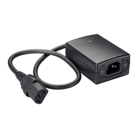
Celexon Professional Radio Trigger operating instructions
Armaturen
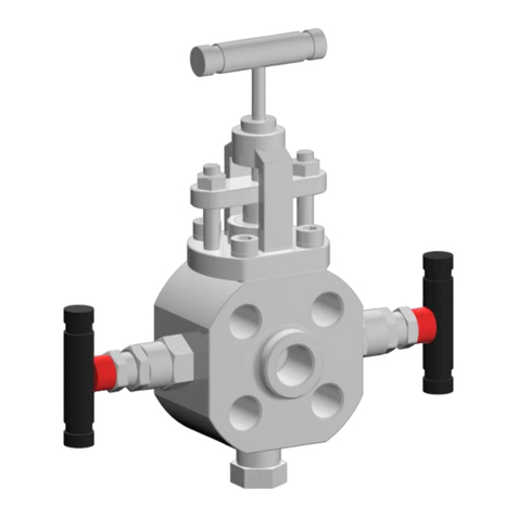
Armaturen Comeval UNIFLOW 8F Installation, operating and maintenance manual

NI
NI SCC-RLY01 user manual
Aetina
Aetina DeviceEdge Orin Nano AIE-CO21 user manual

Fuji Electric
Fuji Electric ALPHA7 instruction manual
Homematic IP
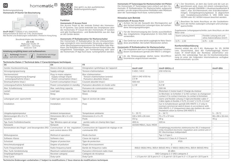
Homematic IP HmIP-SK20 operating manual

IDEC
IDEC HR6S-S Original instructions
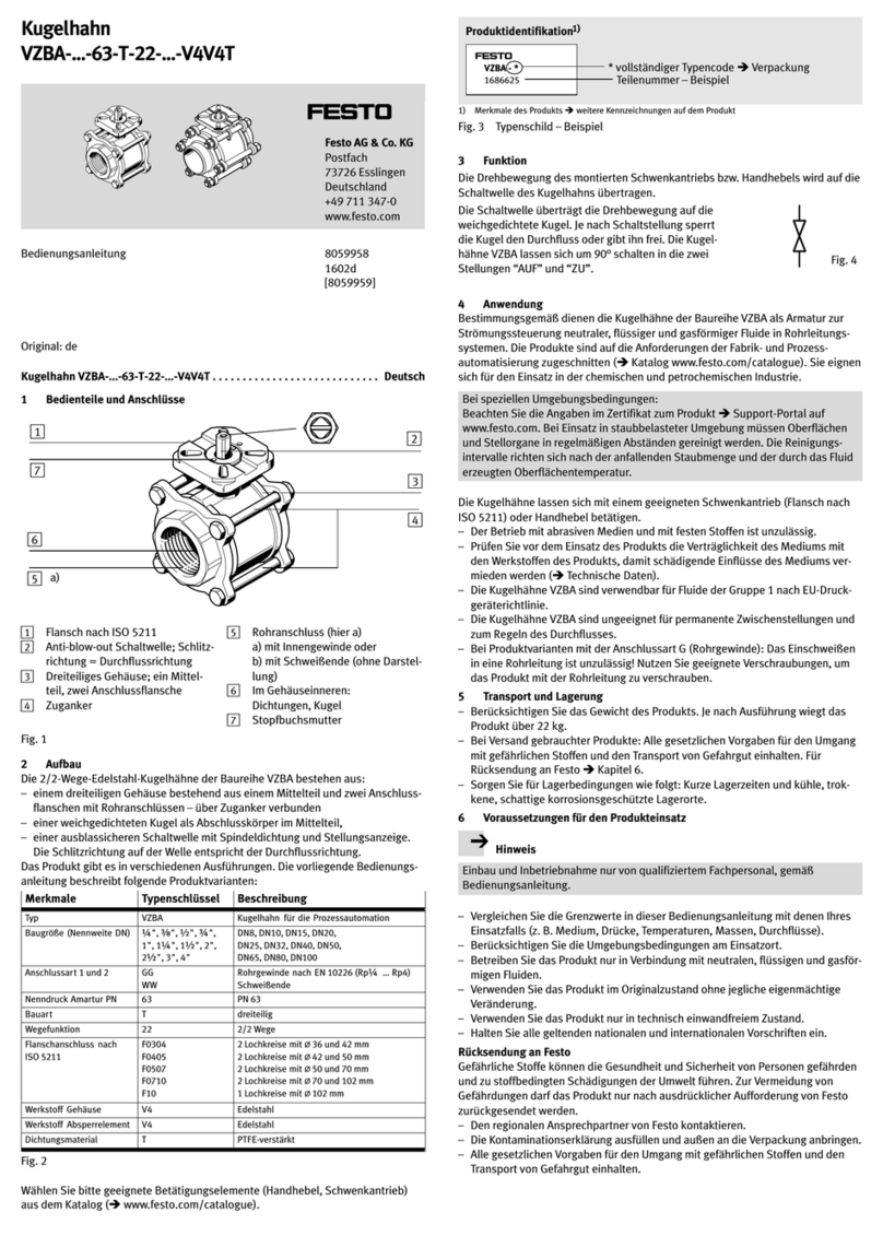
Festo
Festo VZBA-...-63-T-22-...-V4V4T series operating instructions
M-system
M-system R1D-GH2 instruction manual
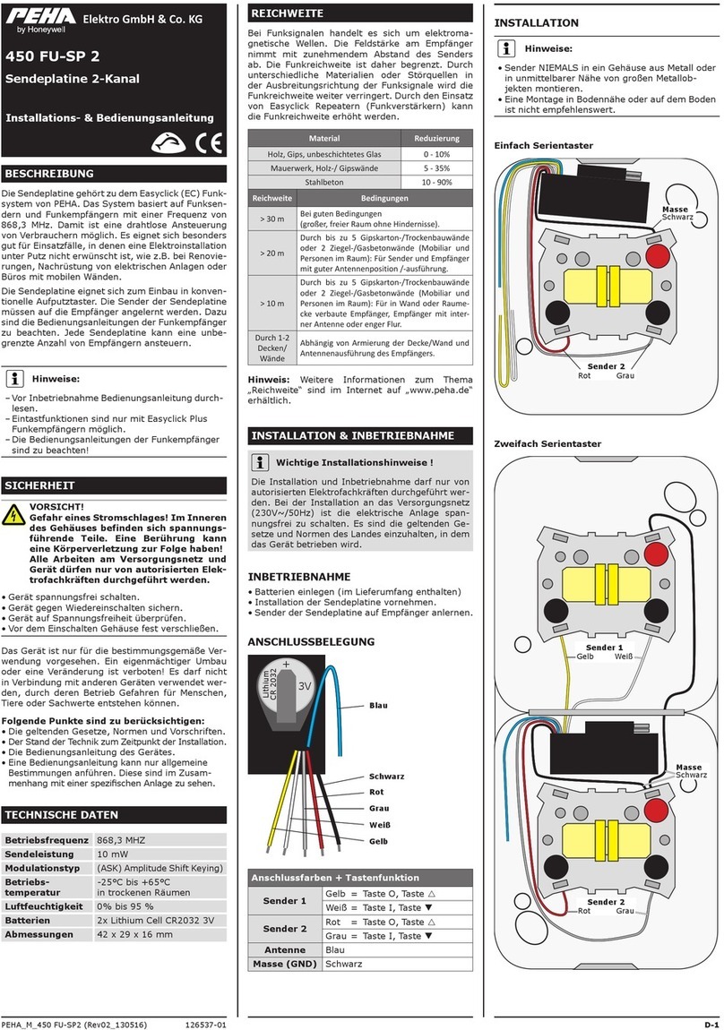
Honeywell
Honeywell PEHA 450 FU-SP 2 Installation and operating instructions
