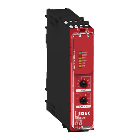
IDEC HR6S-S User manual

http://www.idec.com
HR6S-S
Safety Module
Original instructions
HR9Z-B2202

2HR9Z-B2202 8/2020
The information provided in this documentation contains general descriptions and/or technical
characteristics of the performance of the products contained herein. This documentation is not
intended as a substitute for and is not to be used for determining suitability or reliability of these
products for specific user applications. It is the duty of any such user or integrator to perform the
appropriate and complete risk analysis, evaluation and testing of the products with respect to the
relevant specific application or use thereof. Neither IDEC CORPORATION nor any of its affiliates
or subsidiaries shall be responsible or liable for misuse of the information contained herein. If you
have any suggestions for improvements or amendments or have found errors in this publication,
please notify us.
You agree not to reproduce, other than for your own personal, noncommercial use, all or part of
this document. You also agree not to establish any hypertext links to this document or its content.
IDEC CORPORATION does not grant any right or license for the personal and noncommercial use
of the document or its content, except for a non-exclusive license to consult it on an "as is" basis,
at your own risk. All other rights are reserved.
All pertinent state, regional, and local safety regulations must be observed when installing and
using this product. For reasons of safety and to help ensure compliance with documented system
data, only the manufacturer should perform repairs to components.
When devices are used for applications with technical safety requirements, the relevant
instructions must be followed.
Failure to use IDEC CORPORATION software or approved software with our hardware products
may result in injury, harm, or improper operating results.
Failure to observe this information can result in injury or equipment damage.
© 2020 IDEC CORPORATION. All rights reserved.

HR9Z-B2202 8/2020 3
Table of Contents
Safety Information. . . . . . . . . . . . . . . . . . . . . . . . . . . . . . 5
About the Book . . . . . . . . . . . . . . . . . . . . . . . . . . . . . . . . 9
Chapter 1 Introduction . . . . . . . . . . . . . . . . . . . . . . . . . . . . . . . . . . . 15
Device Overview . . . . . . . . . . . . . . . . . . . . . . . . . . . . . . . . . . . . . . . . . 16
Front View and Side View . . . . . . . . . . . . . . . . . . . . . . . . . . . . . . . . . . 17
Nameplate . . . . . . . . . . . . . . . . . . . . . . . . . . . . . . . . . . . . . . . . . . . . . . 18
Type Code . . . . . . . . . . . . . . . . . . . . . . . . . . . . . . . . . . . . . . . . . . . . . . 19
Chapter 2 Technical Data . . . . . . . . . . . . . . . . . . . . . . . . . . . . . . . . 21
Environmental Conditions . . . . . . . . . . . . . . . . . . . . . . . . . . . . . . . . . . 22
Mechanical Characteristics . . . . . . . . . . . . . . . . . . . . . . . . . . . . . . . . . 24
Electrical Characteristics . . . . . . . . . . . . . . . . . . . . . . . . . . . . . . . . . . . 26
Timing Data . . . . . . . . . . . . . . . . . . . . . . . . . . . . . . . . . . . . . . . . . . . . . 29
Data Functional Safety . . . . . . . . . . . . . . . . . . . . . . . . . . . . . . . . . . . . 31
Chapter 3 Engineering. . . . . . . . . . . . . . . . . . . . . . . . . . . . . . . . . . . 33
Electromagnetic Compatibility (EMC) . . . . . . . . . . . . . . . . . . . . . . . . . 34
Basic Principles of Operation . . . . . . . . . . . . . . . . . . . . . . . . . . . . . . . 35
Safety-Related Inputs . . . . . . . . . . . . . . . . . . . . . . . . . . . . . . . . . . . . . 40
Synchronization of Safety-Related Inputs . . . . . . . . . . . . . . . . . . . . . . 42
Dynamization. . . . . . . . . . . . . . . . . . . . . . . . . . . . . . . . . . . . . . . . . . . . 43
Signal Interlock Monitoring . . . . . . . . . . . . . . . . . . . . . . . . . . . . . . . . . 45
Chapter 4 Installation. . . . . . . . . . . . . . . . . . . . . . . . . . . . . . . . . . . . 47
Prerequisites and Requirements . . . . . . . . . . . . . . . . . . . . . . . . . . . . . 48
Mechanical Installation . . . . . . . . . . . . . . . . . . . . . . . . . . . . . . . . . . . . 49
Electrical Installation . . . . . . . . . . . . . . . . . . . . . . . . . . . . . . . . . . . . . . 51
Chapter 5 Functions . . . . . . . . . . . . . . . . . . . . . . . . . . . . . . . . . . . . 57
Application Functions . . . . . . . . . . . . . . . . . . . . . . . . . . . . . . . . . . . . . 58
Start Functions . . . . . . . . . . . . . . . . . . . . . . . . . . . . . . . . . . . . . . . . . . 69
Chapter 6 Configuration and Commissioning . . . . . . . . . . . . . . . . . 75
Configuration . . . . . . . . . . . . . . . . . . . . . . . . . . . . . . . . . . . . . . . . . . . . 76
Commissioning . . . . . . . . . . . . . . . . . . . . . . . . . . . . . . . . . . . . . . . . . . 78
Chapter 7 Diagnostics . . . . . . . . . . . . . . . . . . . . . . . . . . . . . . . . . . . 79
Diagnostics via LEDs. . . . . . . . . . . . . . . . . . . . . . . . . . . . . . . . . . . . . . 80
Diagnostics via Status Output Z1 . . . . . . . . . . . . . . . . . . . . . . . . . . . . 83

4HR9Z-B2202 8/2020
Chapter 8 Accessories, Service, Maintenance, and Disposal. . . . . . 87
Accessories . . . . . . . . . . . . . . . . . . . . . . . . . . . . . . . . . . . . . . . . . . . . . 88
Maintenance. . . . . . . . . . . . . . . . . . . . . . . . . . . . . . . . . . . . . . . . . . . . . 89
Transportation, Storage, and Disposal. . . . . . . . . . . . . . . . . . . . . . . . . 90
Service Addresses . . . . . . . . . . . . . . . . . . . . . . . . . . . . . . . . . . . . . . . . 91
Index . . . . . . . . . . . . . . . . . . . . . . . . . . . . . . . . . . . . . . . . . 93

HR9Z-B2202 8/2020 5
Safety Information
Important Information
NOTICE
Read these instructions carefully, and look at the equipment to become familiar with the device
before trying to install, operate, service, or maintain it. The following special messages may appear
throughout this documentation or on the equipment to warn of potential hazards or to call attention
to information that clarifies or simplifies a procedure.
DANGER
DANGER indicates a hazardous situation which, if not avoided, will result in death or serious
injury.
WARNING
WARNING indicates a hazardous situation which, if not avoided, could result in death or serious
injury.
CAUTION
CAUTION indicates a hazardous situation which, if not avoided, could result in minor or moderate
injury.
NOTICE
NOTICE
is used to address practices not related to physical injury.

6HR9Z-B2202 8/2020
PLEASE NOTE
Electrical equipment should be installed, operated, serviced, and maintained only by qualified
personnel. No responsibility is assumed by IDEC CORPORATION for any consequences arising
out of the use of this material.
A qualified person is one who has skills and knowledge related to the construction and operation
of electrical equipment and its installation, and has received safety training to recognize and avoid
the hazards involved.
QUALIFICATION OF PERSONNEL
Only appropriately trained persons who are familiar with and understand the contents of this
manual and all other pertinent product documentation as well as all documentation of all
components and equipment of the machine/process are authorized to work on and with this
product.
The qualified person must be a certified expert in safety engineering.
The qualified person must be able to detect possible hazards that may arise from parameterization,
modifying configurations, settings, and wiring, and generally from mechanical, electrical, or
electronic equipment. The qualified person must be able to understand the effects that
modifications to configurations, settings, and wiring may have on the safety of the
machine/process.
The qualified person must be familiar with and understand the contents of the risk assessment as
per ISO 12100-1 and/or any other equivalent assessment as well as all documents related to such
risk assessment or equivalent assessments for the machine/process.
The qualified person must be familiar with the standards, provisions, and regulations for the
prevention of industrial accidents, which they must observe when designing, implementing, and
maintaining the machine/process.
The qualified person must be thoroughly familiar with the safety-related applications and the non-
safety-related applications used to operate the machine/process.
INTENDED USE
This product described in the present document is a safety module intended to perform safety-
related functions in a machine/process according to the present document, to the specified related
documents, and to all other documentation of the components and equipment of the
machine/process.
The product may only be used in compliance with all applicable safety regulations and directives,
the specified requirements and the technical data.
Prior to using the product, you must perform a risk assessment as per ISO 12100-1 in view of the
planned application. Based on the results of the risk assessment, the appropriate safety-related
measures must be implemented.
Since the product is used as a component in an overall machine or process, you must ensure the
safety of persons by means of the design of this overall machine or process.

HR9Z-B2202 8/2020 7
Operate the product only with the specified cables and accessories. Use only genuine accessories.
Any use other than the use explicitly permitted is prohibited and can result in hazards.

8HR9Z-B2202 8/2020

HR9Z-B2202 8/2020 9
About the Book
At a Glance
Document Scope
This manual describes technical characteristics, installation, commissioning, operation and
maintenance of the safety module HR6S-S.
Validity Note
The present document is valid for the products listed in the type code
(see page 19)
.
Related Documents
Title of documentation Reference number
HR6S-S User Guide HR9Z-B2202 (ENG)
HR9Z-B2203 (JPN)
HR6S-S Instruction Sheet B-2187 (JPN, ENG, CHI)
HR6S-EP User Guide HR9Z-B2194 (ENG)
HR9Z-B2195 (JPN)
HR6S-EP Instruction Sheet B-2175 (JPN, ENG, CHI)

10 HR9Z-B2202 8/2020
Product Related Information
This equipment has been designed to operate outside of any hazardous location. Only install this
equipment in zones known to be free of a hazardous atmosphere.
DANGER
HAZARD OF ELECTRIC SHOCK, EXPLOSION OR ARC FLASH
Disconnect all power from all equipment including connected devices prior to removing any
covers or doors, or installing or removing any accessories, hardware, cables, or wires except
under the specific conditions specified in the appropriate hardware guide for this equipment.
Always use a properly rated voltage sensing device to confirm the power is off where and when
indicated.
Where 24 VDC or VAC is indicated, use PELV power supplies conforming to IEC 60204-1.
Replace and secure all covers, accessories, hardware, cables, and wires and confirm that a
proper ground connection exists before applying power to this equipment.
Use only the specified voltage when operating this equipment and any associated products.
Failure to follow these instructions will result in death or serious injury.
DANGER
POTENTIAL FOR EXPLOSION
Install and use this equipment in non-hazardous locations only.
Failure to follow these instructions will result in death or serious injury.

HR9Z-B2202 8/2020 11
1 For additional information, refer to NEMA ICS 1.1 (latest edition), "Safety Guidelines for the
Application, Installation, and Maintenance of Solid State Control" and to NEMA ICS 7.1 (latest
edition), "Safety Standards for Construction and Guide for Selection, Installation and Operation of
Adjustable-Speed Drive Systems" or their equivalent governing your particular location.
WARNING
LOSS OF CONTROL
The designer of any control scheme must consider the potential failure modes of control paths
and, for certain critical control functions, provide a means to achieve a safe state during and
after a path failure. Examples of critical control functions are emergency stop and overtravel
stop, power outage and restart.
Separate or redundant control paths must be provided for critical control functions.
System control paths may include communication links. Consideration must be given to the
implications of unanticipated transmission delays or failures of the link.
Observe all accident prevention regulations and local safety guidelines.1
Each implementation of this equipment must be individually and thoroughly tested for proper
operation before being placed into service.
Failure to follow these instructions can result in death, serious injury, or equipment damage.
WARNING
INSUFFICIENT AND/OR INEFFECTIVE SAFETY-RELATED FUNCTIONS
Verify that a risk assessment as per ISO 12100 and/or other equivalent assessment has been
performed before this product is used.
Before performing any type of work on or with this product, fully read and understand all
pertinent manuals.
Verify that modifications do not compromise or reduce the Safety Integrity Level (SIL),
Performance Level (PL) and/or any other safety-related requirements and capabilities defined
for your machine/process.
After modifications of any type whatsoever, restart the machine/process and verify the correct
operation and effectiveness of all functions by performing comprehensive tests for all
operating states, the defined safe state, and all potential error situations.
Failure to follow these instructions can result in death, serious injury, or equipment damage.

12 HR9Z-B2202 8/2020
Terminology Derived from Standards
The technical terms, terminology, symbols and the corresponding descriptions in this manual, or
that appear in or on the products themselves, are generally derived from the terms or definitions
of international standards.
In the area of functional safety systems, drives and general automation, this may include, but is not
limited to, terms such as
safety
,
safety function
,
safe state
,
fault
,
fault reset
,
malfunction
,
failure
,
error
,
error message
,
dangerous
, etc.
Among others, these standards include:
Standard Description
IEC 61131-2:2007 Programmable controllers, part 2: Equipment requirements and tests.
ISO 13849-1:2015 Safety of machinery: Safety related parts of control systems.
General principles for design.
EN 61496-1:2013 Safety of machinery: Electro-sensitive protective equipment.
Part 1: General requirements and tests.
ISO 12100:2010 Safety of machinery - General principles for design - Risk assessment and risk
reduction
EN 60204-1:2006 Safety of machinery - Electrical equipment of machines - Part 1: General
requirements
ISO 14119:2013 Safety of machinery - Interlocking devices associated with guards - Principles
for design and selection
ISO 13850:2015 Safety of machinery - Emergency stop - Principles for design
IEC 62061:2015 Safety of machinery - Functional safety of safety-related electrical, electronic,
and electronic programmable control systems
IEC 61508-1:2010 Functional safety of electrical/electronic/programmable electronic safety-
related systems: General requirements.
IEC 61508-2:2010 Functional safety of electrical/electronic/programmable electronic safety-
related systems: Requirements for electrical/electronic/programmable
electronic safety-related systems.
IEC 61508-3:2010 Functional safety of electrical/electronic/programmable electronic safety-
related systems: Software requirements.
IEC 61784-3:2016 Industrial communication networks - Profiles - Part 3: Functional safety
fieldbuses - General rules and profile definitions.
2006/42/EC Machinery Directive
2014/30/EU Electromagnetic Compatibility Directive
2014/35/EU Low Voltage Directive

HR9Z-B2202 8/2020 13
In addition, terms used in the present document may tangentially be used as they are derived from
other standards such as:
Finally, the term
zone of operation
may be used in conjunction with the description of specific
hazards, and is defined as it is for a
hazard zone
or
danger zone
in the
Machinery Directive
(
2006/42/EC
) and
ISO 12100:2010
.
Standard Description
IEC 60034 series Rotating electrical machines
IEC 61800 series Adjustable speed electrical power drive systems
IEC 61158 series Digital data communications for measurement and control – Fieldbus for use in
industrial control systems

14 HR9Z-B2202 8/2020

Introduction
16 HR9Z-B2202 8/2020
Device Overview
Outline
The device is a safety module for interruption of safety-related electrical circuits.
The device provides application functions used to monitor signals from different types of
sensors/devices.
Equipment with the following types of outputs can be connected to the safety-related inputs of the
device:
NO, NC, C/O, for example, Emergency Stop push-buttons, guard door switches, coded
magnetic switches, two-hand control devices
PNP transistors, for example, magnetic switches, proximity switches
OSSD, for example, light curtains
The device is available in two different types: Push-in terminals or screw terminals.
Feature summary:
10 application functions
Configurable start function
2 safety-related inputs
2 safety-related relay outputs
1 non-safety-related status/diagnostics outputs
1 non-safety-related start input with 8 selectable start functions
Connector for connection of extension module HR6S-EP to increase the number of safety-
related outputs by 6

Introduction
HR9Z-B2202 8/2020 17
Front View and Side View
Front View and Side View
1 Removable terminal blocks, top
2 Removable terminal blocks, bottom
3 LED indicators
4 Start function selector
5 Application function selector
6 Connector for optional output extension module HR6S-EP (lateral)
7 Sealable transparent cover
3
POWER
ERROR
STAT E
START
S12
S13
S22
S23
1
3
47
2
8
9
56
10
FUNCTION
1
36
27
45
8
START
SAFETY MODULE
HR6S-S
1
4
5
2
6
7

Introduction
18 HR9Z-B2202 8/2020
Nameplate
Nameplate
The nameplate contains the following data:
1 Device type (refer to chapter Type Code
(see page 19)
)
2 Nominal voltage
3 Frequency range VAC supply
4 Input power
5 Maximum current of safety-related outputs with utilization category AC-15 (250 VAC)
6 Maximum current of safety-related outputs with utilization category DC-13 (24 VDC)
7 Maximum total thermal current
8 Maximum Safety Integrity Level (SIL) as per IEC 61508-1:2010
9 Maximum Performance Level and Category as per ISO 13849-1:2015
10 Maximum response time to request at safety-related input
11 Permissible ambient temperature range during operation
12 IP degree of protection
13 Serial number
14 Product version (PV), software version (SV)
15 Plant code and date of manufacture (example: PP-2019-W10 means plant code PP, year of
manufacture 2019, week of manufacture 10)
0DGH LQ ,QGRQHVLD
ವವವವವವವ:ವವ
69 ವವವ39 ವವವ
61 ವವವ
5DWHG 9ROWDJH 8Q ವವವ
)UHTXHQF\ UDQJH $& ವವವ
3RZHU FRQVXPSWLRQ ವವವ
Safety module
'HJUHH RI 3URWHFWLRQ ವವವ
8VH PLQLPXP r& FRSSHU FRQGXFWRUV RQO\
6XUURXQGLQJ DLU WHPSHUDWXUH ವವವ
,(& ವವವ
,62 ವವವ
6HH LQVWUXFWLRQ VKHHW
5HVSRQVH WLPH ವವವ
,WK ವವವ
,(&
$& ವವವ
'& ವವವ
2VDND
-DSDQ
HR6S
ವವವ

Introduction
HR9Z-B2202 8/2020 19
Type Code
Type Code
If you have questions concerning the type code, contact your IDEC CORPORATION service
representative.
Item 1 2 3 4 5 6 7
Type code (example) H R 6 S ‒ S 1 C
Item Meaning
1 ... 4 Product range
HR6S: HR6S safety module
5Product version
S
6Supply voltage
1 = 24 VAC/VDC
7Terminal type
C = Push-in terminals, removable
P = Screw terminals, removable

Introduction
20 HR9Z-B2202 8/2020
Table of contents
Other IDEC Control Unit manuals
IDEC
IDEC MICROSmart FC6A-C16K1CE Use and care manual
IDEC
IDEC MicroSmart pentra FC5A-C10R2 User manual
IDEC
IDEC SmartRelay FL1D Series User manual
IDEC
IDEC FC5A-F2M2 User manual

IDEC
IDEC MicroSmart pentra FC5A-D12K1E User manual
IDEC
IDEC HR1S-ATE User manual

IDEC
IDEC SmartRelay Series User manual
IDEC
IDEC LONWORKS User manual
IDEC
IDEC MicroSmart Series User manual
IDEC
IDEC MICROSmart FC5A Series User manual

