Lead LD-BK10 Series User manual

Temperature Controller of
Dry Transformer
— User Instructions —
LD-BK10 Series
LD-BK10
T
he sensor cable must be removed from the con
troller before the withstand voltage test to prevent
damage to the controller.
在进行耐压测试前,必须将传感电缆从温控器上卸下,以防损坏温控器。
Max Ci
rc M
anu Alarm Trip Fault
Fan Run
Manu/Auto Max/Circ
最大
风机运行
Fan Fault
风机故障
手动/自动 最大/巡回
巡回 超温 跳闸 故障
手动

Safety Guidance
Please read the instructions carefully before installing and operating the controller,
and keep it properly.
Special Product Description:
If the contents of the instruction do not conform to the product, the wiring diagram of the actual
product shall prevail.
Please read the instructions and wiring
diagram carefully before using the
controller.
The controller monitors dangerous power
transformers. If users do not obey a
prescribed procedure to operate, that will
lead to property damage or serious injury
or even death.
Warning
After the controller is powered on, some
terminals are electrified. Please be care-
ful of electric shock.
The sensor cable plug and the power cord
should be separated from the controller
before the transformer voltage test, so as
not to damage the controller!
Only qualified technicians are allowed to
operate the controller. Before operation,
all safety instructions, installation, opera-
tion and maintenance procedures in the
manual should be known.
Make sure that all electrical connections
are correct and secure. The controller
must be grounded reliably.
The controller may only be used for the
purpose specified by our company, and
unauthorized modifications may cause the
controller to malfunction or even fail.
Please note the use conditions of the
controller, especially the humid environ-
ment.
Attention
Do not use a lighter to grill the sensor,
otherwise the sensor will fail.
Undefined terminals are not allowed to
use.
Please put the instructions in an easy place and give it to all users.
The controller is avoided to be used in the
atmosphere contains sulfur dioxide,
hydrogen sulfide and other corrosive gases
using, otherwise it will be damaged.
Do not apply a voltage or current that is
greater than the rated value on the output
terminals.
*

LD-BK10
T
he sensor cable must be removed from the con
troller before the withstand voltage test to prevent
damage to the controller.
在进行耐压测试前,必须将传感电缆从温控器上卸下,以防损坏温控器。
Max Circ Manu Alarm Trip Fault
Fan Run
Manu/Auto Max/Circ
最大
风机运行
Fan Fault
风机故障
手动/自动 最大/巡回
巡回 超温 跳闸 故障
手动
List of items
传感电缆插头
说明书
1. The temperature controller
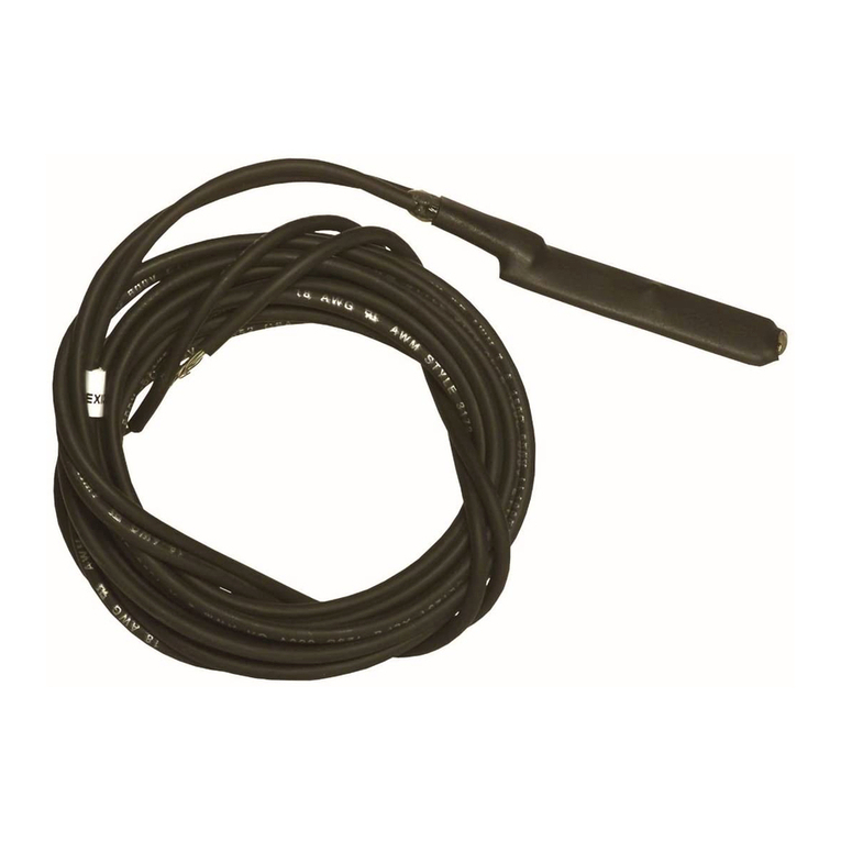
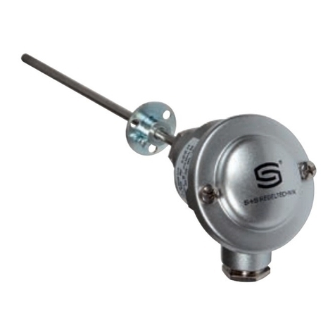
2. The sensor assembly
3. The key
4. The instruction
The temperature controller
The sensor assembly
The key
The instruction

CONTENTS
01Product overview
03The technical specif ication
04Model function
05Installation steps
09Panel shows
10Operation Setup
154 ~ 20mA current output (Type E)
16
RS485 communication (Type F)
20Fault handling
21Appendix: Wiring diagram, three-packet service

01
Product overview
Safe operation and working life of power transformers depends
largely on the safety and reliability of transformer winding. If the
temperature of transformer winding exceed the temperature
which insulation withstand, it will damage the insulation. This is
one of the most important reasons that transformers cannot
operate normally.
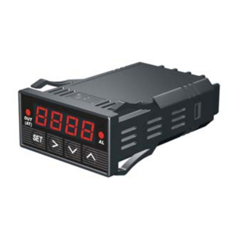
LD-BK10(Q) series temperature controller of dry transformer
(Referred to as temperature controller) is an intelligent control-
ler designed especially for safe operation of dry transformer.
The temperature controller features adoption of single chip
computer technology and utilization of the platinum thermo-re-
sistors embedded in the winding of the dry transformer for
detection and display of temperature rise of the transformer
windings. It can start or stop the cooling fan automatically for
forced air cooling of windings and control over-temp alarm and
over-temp tripping output so that the transformer will be oper-
ated safely.
The temperature controller has good expansibility. It can
expand multiple groups of control output contacts (such as two
groups of over-temp alarm and two groups of over-temp trip)
according to user requirements. It can also design passive con-
tacts with the capacity of DC220v 5A according to user
requirements.

CJX2-1810
NXB-63
C25
400V-
50Hz
6000A
02
LD-BK10
The sensor cable must be removed from the controller before the withstand voltage test to prevent
damage to the controller.
在进行耐压测试前,必须将传感电缆从温控器上卸下,以防损坏温控器。
Max Circ Manu Alarm Trip Fault
Fan Run
Manu/Auto Max/Circ
最大
风机运行
Fan Fault
风机故障
手动/自动 最大/巡回
巡回 超温 跳闸 故障
手动
Layout of controller:
Indicators
Indicators
Operation key
The lock
Sensor assembly
outlet hole
Sensor assembly
socket
Terminal block
Micro Circuit
Breaker
outlet hole
LED display

03
The technical specif ication
1. Operating conditions
-30.0℃~240.0℃
2. Range of measurement
Grade of accuracy: Grade 1(Grade 0.5 for temperature controller, Grade B for
sensor);
Resolution: 0.1℃
3. Measurement accuracy
400mm×320mm×120mm(H×W×D)
4. Overall dimension
≤12W
5. Power consumption of temperature controller
About 5kg
6. Weight
Capacity of contact of fan: 16A/250VAC (cosΦ=0.4);
Capacity of control output: 5A/250VAC (Resistance); 5A/30VDC
7. Contact capacity
JB/T7631-2016 Electronic Thermo-controllers for Transformers
ISO9001:2015 Quality Management Systems-requirements
Ambient temperature: -20℃~+55℃;
Relative humidity: < 95%(25℃);
Power frequency: 50Hz or 60Hz(±2Hz);
Power voltage: AC220V(+10%, -15%);
or AC380V (+10%, -15%);
(If there is no special indication when ordering, AC220V shall
prevail)
8. Standards of design and production

Type selection (any combination between E, F, G/I, L and C)
LD-BK10 - /T
04
Model function
Serial number
of controller
Special
functional
requirements
220: Power
supply
AC220V
380: Power
supply
AC380V
D : Conventional type
E : D+4~20mA current output
F : D+RS485 communication
G: D+1 channel ambient
temperature measurement
and control
I : D+1 channel iron core
temperature measurement
and control
L: Fan fault
C: D+PTC over-temp
alarm(optional)
PTC over-temp trip(option-
al)

A rectangular mounting hole 302x372mm is
opened on the transformer housing.
4 Φ4.5 fixed holes (160x385mm) are opened
on the transformer housing according to the
size of the embedded installation fixed hole.
Open the controller cover and remove 4
screws and fixing plates.
Install the L-shaped fixing piece and fasten
the temperature controller to the transformer
housing with 4 M4 screws.
Embedded installation hole size: 372×302mm(High x width)
Fixed hole size: 385mm×160mm (High x width)
Embedding depth: 90mm
Fixed hole size: φ4.5
Scan code to watch
"Installation Video"
160mm
302mm
372mm
385mm
90mm
1
LD-BK10
Thesensor cable must be removed from the controller before the withstand voltage test to prevent
damage to the controller.
在进行耐压测试前,必须将传感电缆从温控器上卸下,以防损坏温控器。
Max Circ Manu Alarm Trip Fault
FanRun
Manu/Auto Max/Circ
最大
风机运行
FanFault
风机故障
手动/自动 最大/巡回
巡回 超温 跳闸 故障
手动
变压器外壳
3
Fixing piece
Transformer housing
Installation steps
05
1. Temperature controller installa-
tion (embedded)
2
变压器外壳
4
Transformer housing

Note:correspondence between leader color of sensor and phase:
Yellow corresponds to phase A; Green corresponds to phase B;
Red corresponds to phase C; Blue corresponds to channel d.
(1) D25 sensing cable (3-wire system), Cable length tolerances: ±2.5%
Connection diagram of type D/E/F 3-channel sensing assembly
06
2. Sensing Cable Assembly
传感电缆插头
LA
LB
LC
Red Green Yellow
Connection diagram of type G/I 4-channel sensing assembly
传感电缆插头
LA
LB
LC,Ld
Red
Blue
Green Yellow
Pt100 sensor
Cable
D25 sensor assembly plug
Pt100 sensor
Cable
D25 sensor assembly plug

A. Pt100 platinum resistor is a thermo-resistor with better linearity in the range
of -30.0℃~240.0℃ and meets the requirements for Grade B set forth in
GB/T8622-97-- Technical Specification and Reference Table for Industrial
Platinum Resistance.
B. Overall dimension: Ф4mm×40mm
(2) Sensor
A. Electrical parameters
Operating temperature range:0.0℃~70.0℃
Operating humidity range:0.0%RH~100.0%RH (Condensable)
Detection range: 0.0%RH~99.9%RH
Storage temperature range:Below 95.0%RH (Condensable)
Detection accuracy: ±5%RH
(3) Humidity module (optional function)
07
A. Explanation of PTC
PTC is an abbreviation for positive temperature coefficient thermistor, which is
a semiconductor resistor having a typical temperature sensitivity. When the
temperature exceeds a certain value (Fixed temperature point not be adjust-
able), its resistance value will increase impulsively with increasing temperature,
i.e., resistance mutation.
B. Logical relation of interlock control of Pt100 and PTC
a. Interlock control of Pt100 and PTC on over-temp alarm
• When the temperature measured by Pt100 exceeds over-temp alarm
value, in addition, PTC reaches the point of over-temp alarm and the resis-
tance has mutated. Over-temp alarm signal will output.
b. Interlock control of Pt100 and PTC on over-temp trip
• When the temperature measured by Pt100 exceeds over-temp trip value,
in addition, PTC reaches the point of over-temp trip and the resistance has
mutated. Over-temp trip signal will output.
(4) Interlock control of Pt100 and PTC on over-temp alarm and over-temp trip
signal (optional function)

a. Two options:
b. We offer PTCAL and PTCAH whose temperature point is as same as the
controller setting for over-temp alarm and over-temp trip. Over-temp alarm
PTC is PTC130, over-temp trip PTC is PTC150. PTC temperature point of
resistance mutation is fixed value could not be adjustable. If users need to
change the PTC temperature point, please make a note when ordering.
• PTCAL&PTCAH: Involved in controlling over-temp alarm and over-temp
trip signal output
• PTCAH: Involved in controlling over-temp trip signal output
C. PTC status query of over-temp alarm and trip (Function code 1006)
D. About PTC ordering
08
Normal display status
Note1: Good: PTC of over-temp trip is normal;
-OP-: PTC of over-temp trip is open circuit;
-OL-: PTC of over-temp trip is short circuit.
Note2: Good: PTC of over-temp alarm is normal;
-OP-: PTC of over-temp alarm is open circuit;
-OL-: PTC of over-temp alarm is short circuit

Maximum temperature display
Circuit temperature display
Manual mode
Over-temp alarm
One-bit digital
display, showing
the measurement
phase and prompt-
ing characters
Four-bit digital
display, showing the
measured value and
parameters
Over-temp trip
Senor or controller fault alarm/ Out
of temperature range
Fan run
Fan fault
Panel shows
09
1. Indicator
2. Key
3. Display
Max Circ Manu Alarm Trip Fault
Fan Run
Manu/Auto Max/Circ
最大
风机运行
Fan Fault
风机故障
手动/自动 最大/巡回
巡回 超温 跳闸 故障
手动
Max
最大
Circ
巡回
Fan Run
风机运行
Fan Fault
风机故障
Alarm
超温
Trip
跳闸
Fault
故障
Manu
手动
Max/Circ
最大/巡回
Manu/Auto
手动/自动
Reset key
Set key
Manual fan start/ automatic fan
mode-Switch
Parameter setting increasing key, long
press to increase rapidly
Maximum temperature/ circuit tempera-
ture mode-Switch
Parameter setting decreasing key, long
press to decrease rapidly
Temperature display: if phase A is 48.2, will be displayed
Function code display: if function code is 1005, will be displayed
Parameter modify: if parameter value is 90.0, will be displayed

Operation Setup
10
Common Function Codes Diagram
Note: ① When displaying the function prompt, press key SET to enter into the
corresponding data display.
② The following parameters are conventional default values. Details are
subject to the controller certification or the wiring figure.
③ During the key operation, if no key is pressed, the thermostat will auto-
matically return to its normal working state after about 100 seconds, and the
previous setting is invalid.
Black box
Timing start
stop of fan
Control
parameter
Temperature
compensation
Normal display status
Fan fault
parameters
Temperature
simulation
Normal display status

1. Black Box (P1002): View the temperature of each phase when the controller is
powered failure.
2. Timing Start Stop of Fan (P1003): Set up the time interval for the start-up of
the cooling fan
11
Note: Chanel d is avail-
able for types G/I only.
Note: The spacing interval is expressed in a
unit of hour with a set range of 0~150.
The auto operation time of the fan is set as
2 minutes by the software and user is unable
to change it.
For example: If 0 is set, it indicates the fan
has no timed start/stop function; If 24 is
set, the fan will start once at an interval of
24 hours. The user can set the interval in
light of the actual conditions.
Temperature of phase
A before power failure
Temperature of phase
B before power failure
Temperature of phase
C before power failure
Temperature of channel
d before power failure
Normal display status
Timing start
stop interval
Intervaltime
setting
Normal display status

Ob: target value for start/stop of fan
AH: target value for over-temp trip
ObJ: target value for start/stop of
transformer room fan
AHJ: target value for over-temp
tripping in transformer room
Hb: target value for start/stop of
dehumidification heater
Starting temperature of fan>Ob+dF
Starting temperature of fan in
transformer room>ObJ+dFJ
Starting temperature of dehumidifi-
cation heater>Hb+HdF
dF: backlash of target value for
start/stop of fan
AL: target value for over-temp alarm
dFJ: backlash of target value for
start/stop of fan in transformer room
ALJ: target value for iron core over-temp
alarm
HdF: backlash of target value for
start/stop of dehumidification heater
Stopping temperature of fan<Ob-dF
Stopping temperature of fan in trans-
former room<ObJ-dFJ
Stopping temperature of dehumidifica-
tion heater<Hb-HdF
Note: ① The backlash of target value is 0.3 ℃ by default, except those for cooling fan, trans-
former room fan and dehumidification heater.
② The parameters shown above are all for reference and specific set value shall be subject
to the delivery label.
Example: If Ob=90.0 dF=10.0, then the starting temperature is 100.1 ℃, the stop tempera-
ture is 79.9 ℃.
3. Control Parameters Modification (P1005)
12
Modified
value AHJ
Modified value Ob
Modified value dF
Modified value AH
Modified value AL
Modified
value ALJ
Modified
value dFJ
Modified
value ObJ
Modified
value HdF
Modified
value Hb
Normal display status
Operation stips of winding
temerature measurement
Operation steps for ambient
temperature measurement
Operation steps for iron core
temperature measurement
Operation steps for ambient
humidity measurement

4. Temperature Compensation (P1008):
When there are errors in the display value of the measured temperature, the digital com-
pensation of the measured value corrects the measured value. ( Compensation range:-19.9
℃~-19.9℃)
5. Fan fault parameters(P1011)
13
Real time AD
value of fan
Value of fan
protection
Normal display status
Compensation
value of phase A
Compensation
value of channel d
Compensation
value of phase B
Compensation
value of phase C
Normal display status
Operation steps of 3 channels
Operation steps of 4 channels
① When FC set to 0: no fan fault judgment
function;
When FCx50> Fd, It is considered that the fan
is normal.
When FCx50< Fd, It is considered that the fan
is faulty, the fan fault alarm output.
② Please connect the same number of fans of
the same model and specification on the
terminals of the two groups of fans.
③ Start fans manually, check the Fd value and
set the FC value to be greater than Fd/50.
④ If the fan protection is incorrect after
modification, check the fan and fan wiring.
Refer to point 3.
Note:

6. Temperature Simulation (P1012):
Simulate the change of temperature value and detect the output of controller.
14
Fan star
Over-temp
alarm
Out of range
Fan stop
Over-temp alarm
release
In range
Normal display status
① To prevent the transformer from wrong tripping, the software doesn’t support
analogue function of over-temperature tripping;
② The actual operating temperature point shall be subject to the internal parameter
of temperature controller (1005 function setting).
Note:

1. Functional features
On the basis of the general-purpose function transmission of independent 3-way
(4-way) 4~20mA current signals that are in linear correspondence with the mea-
sured temperature value(0.0℃~200.0℃) will link to the distant A/D card directly so
as to set up a distributed control system(DCS).
Within the temperature controller A-, B-, C- and d- are connected mutually,
namely, with co-negative electrode. If your collecting system is in conflict with it,
please specify before placing order.
2. Technical specifications for current output
(1) Load resistance:R≤500Ω
Output accuracy: ±1%
(2) Corresponding curve and relationship formula between measured temperature
and output current of temperature controller
(3) Conversion of output
Relationship formula between temperature and current: I= (16T/200)+4
Where: T stands for temperature value of winding in X-phase
I stands for current value corresponding to the temperature in the phase.
If the user’s collecting system calls for receipt of analogue voltage signals, 250Ω
resistor with high accuracy may be connected in parallel directly at the existing
current output end. Then 1~5V voltage signals may be received immediately and
connected to the load resistance R≥20kΩ.
4-20mA Current Output (Type E)
15
T(℃)
I(mA
)
420
0
2
00

Original communication
address New communication
address
Normal display status
1. Functional features
Temperature controller has serial communication function and the operating
status of the transformer and temperature controller can be monitored by the
monitoring system.
It usually utilized RS485 interface. If you need additional communication interface
as RS232, RS422, please specify before ordering.
2. Technical indicators
3. Communication address setting
(1) Maximum communication distance: 1200m;
(2) Maximum number of temperature controller to be connected to: 28;
(3) Schematic communications connection diagram:
RS485 communication (Type F)
16
A(+)
B(-)
Up to 1200m
Controller 1 Monitoring
System
Controller N
Table of contents