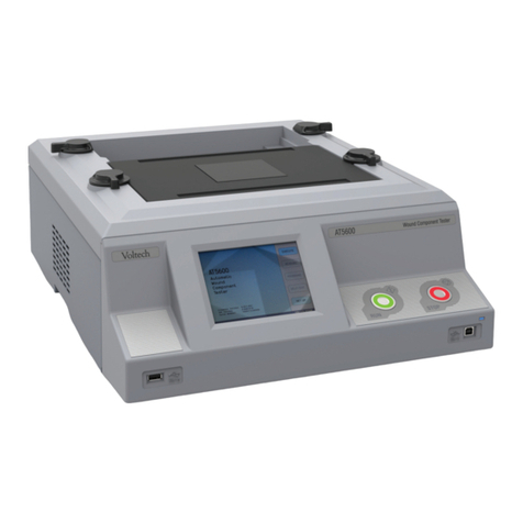
Voltech AT3600 User manual


VPN 98 - 024 V17
AT3600
Automatic Transformer Tester
User Manual
Voltech
2000-2008 Voltech Instruments

VOLTECH AT SERIES USER MANUAL
VPN 98 - 024
Voltech Instruments are committed to a policy of continuous product development. Hence,
product specification and the information given in this manual are subject to change without
notice.
No part of this publication may be produced, stored in a retrieval system, or transmitted in any
form, or by means electronic, mechanical photocopying, recording or otherwise without prior
written permission of Voltech Instruments.
All rights reserved.
2000-2005 Voltech Instruments
Microsoft, Windows, and the Windows logo, are either registered trademarks or trademarks of
Microsoft Corporation in the United States and/or other countries

VOLTECH AT3600 USER MANUAL TABLE OF CONTENTS
VPN 98 -024
VOLTECH AT3600 USER MANUAL
TABLE OF CONTENTS
1. INTRODUCTION
1. Introduction.................….........................................1.1.1
2. AT3600 Features Summary…….…….…….............1.2.1
3. Overview ……….........…........................................1.3.1
2. GETTING STARTED
1. Introduction..................…........................................2.1.1
2. Installing the AT3600....…................………………..2.2.1
3. Quick Start Tutorial...…….......................................2.3.1
4. Firmware Upgrades..…..........…..............................2.4.1
3. TEST PROGRAM EDITOR
1. Introduction ………..................................................3.1.1
2. Schematic Editing..……..........................................3.2.1
3. Creating The Program ............................................3.3.1
4. Programming Tests ................................................3.4.1
4. USING THE SERVER
1. Introduction ........….................................................4.1.1
2. Test Program Handling. …………...........................4.2.1
3. Test Results Handling .........…................................4.3.1
5. FIXTURES
1. Introduction.…….....................................................5.1.1
2. Description of the Fixture System……....………......5.2.1
3. Kelvin Connections……………………………………5.3.1
4. Wire Stripping…………………………..……………..5.4.1

TABLE OF CONTENTS VOLTECH AT3600 USER MANUAL
VPN 98 -024
VOLTECH AT3600 USER MANUAL
TABLE OF CONTENTS -CONTINUED
6. FRONT PANEL OPERATION
1. Introduction.……………...............…........................6.1.1
2. Self Test………..……......................….…................6.2.1
3. Execute Mode………….…................…...................6.3.1
4. Fixture Compensation......…....................................6.4.1
5. Measure Mode………......…....................................6.5.1
6. Program Mode …..…...............................................6.6.1
7. TESTS & TEST CONDITIONS
1. Transformer Tests …..............................….............7.1.1
8. SPECIFICATION
1. Specification............….............................……........8.1.1
2. Interface Details................….......................…........8.2.1
3. Environmental Conditions.....…....................….......8.3.1
4. EMC Compliance.......….................................….....8.4.1
9. WARRANTY AND SERVICE
1. Warranty Information........….................…......….....9.1.1
10. SAFETY SYSTEMS
1. Safety Systems ……..…....................................….10.1
2. Safety Notices ........................….……......................10.5
3. Typical Installation ……………….....….……….........10.6
4. Operation with an IR Safety System ………………10.8
5.Constructing Safe Fixtures …………......................10.11

VOLTECH AT3600 USER MANUAL TABLE OF CONTENTS
CHAPTER 1 - INTRODUCTION
TABLE OF CONTENTS
This chapter will provide an introduction into the setup and use of your
AT3600 Tester.
1. INTRODUCTION
1. HOW TO USE THIS MANUAL….....….................................1.1.1
2. GENERAL SAFETY INSTRUCTIONS….................................1.1.2
3. PACKAGE CONTENTS .........….…...….............................1.1.3
4. PRODUCT IDENTIFICATION ………………………………...1.1.3
2. AT3600 FEATURES SUMMARY
……...…...............................…...….….......................1.2.1
3. OVERVIEW
……………………..........….............…..........................1.3.1
INTRODUCTION VPN 98-024

TABLE OF CONTENTS VOLTECH AT3600 USER MANUAL
VPN 98-024 INTRODUCTION

VOLTECH AT3600 USER MANUAL INTRODUCTION
INTRODUCTION VPN 98 - 024 PAGE 1.1.1.
1. INTRODUCTION
1.1. HOW TO USE THIS MANUAL
Welcome to the Voltech AT3600 wound component tester. Please study this
introductory chapter of the manual carefully. It will help you to setup your tester
quickly and safely. By using your instrument to its full potential, you will increase
the quality and reduce the cost of your transformers and inductors.
The following symbol conventions are used throughout:
Important safety information. To ensure operator safety, all safety information must
be read and understood.
Important information that explains a general principle or refers to other sections of
the manual.
The contents of this manual are believed to be accurate at the time of printing.
Voltech reserves the right, however, to change the operation or specification of
the AT3600 tester without notice. No liability is accepted for the
inappropriate, negligent, or incorrect set-up of the AT3600 tester by the user,
by either manual or automated means.
The Voltech AT3600 is protected by the following patents:
USA: US 5500598
UK: 2261957B
Europe: 0621953B
i
!

INTRODUCTION VOLTECH AT3600 USER MANUAL
PAGE 1.1.2. VPN 98 - 024 INTRODUCTION
1.2. GENERAL SAFETY INSTRUCTIONS
DANGER OF ELECTRIC SHOCK
Only qualified personnel should install this equipment, after reading and
understanding this users manual. If in doubt, consult your supplier.
WARNING: The AT tester must be connected to a safety ground (earth).
Only insert the power lead into a socket with a protective ground contact.
Ensure that the power lead is in good condition and free from damage
before use.
Replace the fuse only with the same type and rating: 3.15AT
Refer servicing only to qualified personnel who understand the danger of shock
hazards.
WARNING: The AT3600 wound component tester can generate voltages that may
be LETHAL. The safety interlock is designed to ensure the safety of operators
when used with a Voltech approved safety system. To ensure operator safety, this
interlock must always be properly connected to a Voltech approved safety system.
DANGER OF ELECTRIC SHOCK
Only qualified personnel should install this equipment, after reading and
understanding this user manual. If in doubt, consult your supplier.
RISQUE D'ELECTROCUTION
L'installation de cet équipement ne doit être confiée qu'à un personnel qualifié
ayant lu et compris le présent manuel d'utilisation. Dans le doute, s'adresser au
fournisseur.
GEFAHR VON ELEKTRISCHEM SCHOCK
Nur entsprechend ausgebildetes Personal ist berechtigt, diese Ausrüstung nach dem
Lesen und Verständnis dieses Anwendungshandbuches zu installieren. Falls Sie
Zweifel haben sollten, wenden Sie sich bitte an Ihren Lieferanten.
RISCHIO DI SCARICHE ELETTRICHE
Solo personale qualificato può installare questo strumento, dopo la lettura e la
comprensione di questo manuale. Se esistono dubbi consultate il vostro rivenditore.
!
!
!
!
!
!
!
!
!
!
!

VOLTECH AT3600 USER MANUAL INTRODUCTION
INTRODUCTION VPN 98 - 024 PAGE 1.1.3.
1.3. PACKAGE CONTENTS
The following items are supplied in the packing case along with this manual:
1. AT3600 transformer tester.
2. Power cord.
3. CD-ROM inside the cover of this manual, which contains the Editor and
Server installation files and other important information.
4. 9pin’D’ – 9pin’D’ F-F Cable.
5. 9pin’D’ – 25pin’D’ F-F Cable.
6. 25pin’D’ – 25pin’D’ F-F Cable.
7. This AT Series user manual.
8. Calibration certificate.
9. A Voltech product registration card.
Please report any missing items to your Voltech supplier. Returning your product
registration card will ensure that you continue to receive the latest product and
application information.
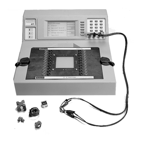
1.4. AT3600 AND ATI
The AT3600 is one of a family of automatic testers from Voltech that share the
same fixture construction and PC editor and server software. ATi’s and AT3600’s
can share the same server application, simultaneously recalling test programs and
recording test results.
AT3600 ATi
ii
i

INTRODUCTION VOLTECH AT3600 USER MANUAL
PAGE 1.1.4. VPN 98 - 024 INTRODUCTION
Features: ATi AT3600
20 wa
y
switchin
g
matri
x
!!
PC test editor and results server !!
Test fixture s
y
stem !!
Small si
g
nal tests
(
e.
g
. inductance
,
ca
p
acitance
,
turns !!
Telecomms. tests
(
e.
g
. return loss
,
lon
g
itudinal !!
Insulation resistance 500V 7000V
Hi-
p
ot
(
AC
)
5500V
Hi-
p
ot
(
DC
)
7000V
Sur
g
e tes
t
in
g
5000V
Ma
g
netizin
g
current and o
p
en circuit volta
g
e 270V
Watts
,
Stress Watts !
Leaka
g
e Curren
t
!
Hi-
p
ot Ram
p
(
AC
)
5500V
Hi-
p
ot Ram
p
(
DC
)
7000V
Also available for the AT3600, the Voltech 'AC Source Interface' extends the
possible test range of the AT3600 test signal generators up 600V, 10A when used
with a suitable external supply.
Over 35 different tests are available for the AT3600. Check our website at
www.voltech.com for details of new tests. Most can be installed within a few
minutes by purchasing a software upgrade.
To determine which options were installed on your tester during manufacture, check
the list attached to the calibration certificate inserted in the pocket on the inside
front cover of this manual.
i

VOLTECH AT3600 USER MANUAL AT3600 FEATURES SUMMARY
INTRODUCTION VPN 98 - 024 PAGE 1.2.1.
2. AT3600 FEATURES SUMMARY
Your AT3600 tester is designed for fast, accurate and reliable testing of transformers
and other wound components in a production or goods inwards environment.
However, it is a complex instrument with many ways in which it can be set up and
used.
Therefore, it is important that you take the time to read this section and the Overview
in the following section, in order to understand the product capabilities, and enable
you to make the best use of your AT3600 in your particular environment.

AT3600 FEATURES SUMMARY VOLTECH AT3600 USER MANUAL
PAGE 1.2.2. VPN 98 - 024 INTRODUCTION
TYPICAL INSTALLATION
TEST PROGRAM CREATION
• Simple, easy to use, Windows based Editor for creating test programs.
(Chapter 3.)
• Requires no software programming skills or expertise.
• Test conditions may be entered manually, or chosen automatically by
measuring a sample transformer.
PROGRAM ARCHIVE MANAGEMENT
• Windows based Server software for easy management of all test programs.
(Chapter 4.)
• Optionally, programs may be resident in the AT3600 Tester for stand-alone
operation.
Editor PC - used when creating
or editing test programs. Server PC - for handling detailed
results and large numbers of test
programs.
Untested
transformers
PASS FAIL
Tested transformers

VOLTECH AT3600 USER MANUAL AT3600 FEATURES SUMMARY
INTRODUCTION VPN 98 - 024 PAGE 1.2.3.
OPERATION
• Manual or robotic operation
• Barcode input
• Footswitch input
• Simple PASS / FAIL operation by an unskilled operator
• Safe – Light barrier controlled power isolation prevents operator injury from
high voltages. (Chapters 8 & 10.)
RESULTS
• Direct printing from the AT Series Tester.
• Results archiving to disk using the Server application.
• Results for analysis can be easily exported to other Windows applications.
AT MEASUREMENTS
Versatile – Many different types of test are all performed automatically. The range of
tests available is being constantly expanded, but common test types include:
• Continuity
• DC Resistance
• Primary Inductance (Series or Parallel)
• Q Factor
• Equivalent Resistance (Series or Parallel)
• Leakage Inductance
• Capacitance
• Turns Ratio and Phasing
• Inductance with Bias Current (Series or Parallel)
• Insulation Resistance
• Magnetizing Current
• Open Circuit Voltage
• Hi-Pot (DC)
• Hi-Pot (AC)
• Surge Stress Test
• Hi-Pot Ramp (AC)
• Hi-Pot Ramp (DC)

AT3600 FEATURES SUMMARY VOLTECH AT3600 USER MANUAL
PAGE 1.2.4. VPN 98 - 024 INTRODUCTION
• Modular Upgrades - Each individual test is independent of the others,
therefore only the tests required need to be purchased for each tester.
Additional tests may be added as required via a firmware upgrade, see chap
7 section 1.1 for the tests currently available.
• Fast - Achieving an average of 10 tests per second including switching of the
relay matrix.
• Accurate - Fully programmable signal sources and high-resolution
‘intelligent’ digital measurements.
• Reliable - Totally integrated signal sources, switching matrix and
measurement circuits under microprocessor control ensure low stress on all
circuits.
OVERVIEW
The next section gives a more detailed overview of your AT3600 Tester and how to
use it. It is recommended that you read this section before attempting to use your
tester.

VOLTECH AT3600 USER MANUAL OVERVIEW
INTRODUCTION VPN 98 - 024 PAGE 1.3.1.
AT3600 OVERVIEW
TOPICS COVERED IN THIS OVERVIEW
• The features and functionality of the AT3600 tester.
• Internal functionality.
• How the tester executes each test.
• What appears in a test program.
• How programs are created, archived and then used in actual test.
• Test fixtures.
• Typical manual and robotic test situations.
• Safety systems.
Note: This overview is intended as an introduction to each of the above topics, so
that you may quickly understand what may be possible. If further details are
required on any topic, they can be found in later chapters of this manual.

OVERVIEW VOLTECH AT3600 USER MANUAL
PAGE 1.3.2 VPN 98-024 INTRODUCTION
BEHIND THE FRONT PANEL
The internal functionality of the AT3600 tester is summarized in the following figure:
You do not need to know how each block functions in order to use the tester. The
following explanation is included for readers who wish to know more.
Test Nodes
These are the spring-loaded ATE pins that can be seen on the top surface of the tester.
Each node is made up of two contacts - a ‘power’ pin, and a ‘sense’ pin - forming a Kelvin pair.
Relay Switching Matrix
The purpose of the relay-switching matrix is to connect the selected test source and
measurement circuits to the particular nodes required in the test.
The matrix is a crucial component in the performance of the AT Series tester. It is made up of
very advanced, high speed, high voltage reed relays, capable both of holding off the 7000V test
voltages used in Hi Pot tests, and of accurately switching the very small voltages and currents
encountered in other tests. (Lower voltage rating relays are used on the AT1600).
The switching of the relays is carefully controlled by the processors so that there is no arcing
across the contacts. This means that the life of the relays can be guaranteed to last for many
millions of switching operations.
Processors
The AT Series Testers are based on a two-processor design:
A standard microprocessor which acts as controller, and also drives the relay matrix, the
keyboard and display, and the various interfaces.
A fast digital signal processor that controls the test sources and performs the measurements.

VOLTECH AT3600 USER MANUAL OVERVIEW
INTRODUCTION VPN 98 - 024 PAGE 1.3.3.
Test Sources
There are six different test sources within the AT3600.
The processors select which one is to be connected to the relay matrix, as each test is executed.
Measurement Circuits
The AT3600 tester contains a variety of circuits, capable of performing all the following
measurements:
• Voltages from less than 1mV to greater than 7000V,
• Currents from nano-amps to amps,
• DC and harmonic analysis,
• RMS, mean-sense, wattage and VA analysis,
• Transient capture,
and more.
Again, the processors select which is appropriate for each test as it is executed.
Keyboard & Display
The front-panel of the tester contains an LCD graphics panel display, three LED’s, and a
membrane type alpha-numeric keyboard.
To give the greatest versatility and ease of use, the front panel ergonomics are based around
four ‘soft-keys’, which are situated to the right of the display. During operation, the display
provides titles for these keys, allowing them to change with the context, so that the operator is
presented with only the key choices that are relevant at that point in time.
Interfaces
These include the Remote, Bar Code, Auxiliary and Server Ports located on the rear panel, and
the User Port that is at the rear of the top surface.
AC Hi-Pot
DC Hi-Pot
Sur
g
e
Hi
g
hPowe
r
Low Powe
r
Constant Current
Processors
Rela
y
Matrix

OVERVIEW VOLTECH AT3600 USER MANUAL
PAGE 1.3.4 VPN 98-024 INTRODUCTION
HOW DOES THE AT3600 TESTER RUN A TEST?
Because the programming of each test is done at a high level, it is not strictly
necessary for you to know the details of how tests are executed within the tester.
However, for some users this subject may be of interest, therefore a brief explanation
has been included here.
When the test program is loaded into the tester, each individual test is assembled into
a sequence of operations involving the components in the functional block diagram
shown previously. The sequence is different for each test, and in some cases, it
depends on which are the preceding and following tests in the program; but in all
cases, it is optimized to give the best measurement speed and accuracy.
As an example, the sequence for measuring inductance may be summarized as
follows:
For other tests, the sequence may be more complicated.
Notes: All the relay switching is completed before the test source is energized; this
will ensure that there can be no arcing, and prolong the life of the relays.
In contrast to some LCR bridges, the AT Series testers trim the test source to
give the user programmed test conditions. This will guarantee that the same
test conditions are applied to all transformers that use the same test program.
At the end of the test, the source is safely ramped down, so that the relay
switching for any subsequent test will always occur with the source removed.

VOLTECH AT3600 USER MANUAL OVERVIEW
INTRODUCTION VPN 98 - 024 PAGE 1.3.5.
CREATING PROGRAMS - THE EDITOR
The test program is simply the list of tests that you wish to apply to your transformer.
Clearly individual transformers will each have their own program, but as an example,
a typical program for a three winding switch-mode power supply transformer could
be as follows:
The Test Program Editor supplied with your tester allows you to create such a
program simply and easily without any need for software programming skills. Each
test required for the program is selected from a list of ‘available tests’ by clicking
with the mouse. The test details (such as the transformer terminals, test conditions,
and pass / fail limits) are then entered into a form fill dialogue box.
Normally, the Editor is used with the Auxiliary Port of the Tester connected to a
spare Com-Port on the PC:
Pull-down menus in the Editor would then allow you to download the program to the
tester, so that it may be run for the purposes of evaluation and modification.
Auxiliary port
PC running the
Editor software
Other manuals for AT3600
1
Table of contents
Other Voltech Test Equipment manuals
Popular Test Equipment manuals by other brands

EXFO
EXFO IQS-2150 user guide

Clas Ohlson
Clas Ohlson UNI-T UT18C instruction manual

SCS
SCS 724VK2 Operation instructions

Teledyne Lecroy
Teledyne Lecroy frontline TLF 3000 user manual

Meilhaus Electronic
Meilhaus Electronic MEphisto Scope UM202 quick start guide

DENTSPLY
DENTSPLY AUSTENAL ELECTROMATIC-4 Operation manual