Leadshine Technology M880A User manual

User sManual
For
M880A
HighPerformanceMicrosteppingDriver
Version 1.0
2008 All RightsReserved
Attention: Pleasereadthismanualcarefullybeforeusingthedriver!
3/F,Block2, Nanyou Tianan IndustrialPark,Nanshan Dist, Shenzhen,China
T:(86)755-26434369 F:(86)755-26402718
Website: www.leadshine.com E-Mail: sales@leadshine.com
The contentinthismanualhas been carefullyprepared and isbelievedtobe accurate,butno
responsibilityisassumed forinaccuracies.
Leadshinereservestherighttomakechangeswithoutfurthernoticetoany productshereinto
improvereliability,function ordesign.Leadshine doesnotassumeanyliabilityarising outofthe
application oruseofanyproductorcircuitdescribed herein;neitherdoesit conveyanylicense
underitspatentrightsofothers.
Leadshine sgeneralpolicydoesnotrecommend theuseofitsproductsinlifesupportoraircraft
applicationswhereinafailureormalfunctionofthe productmaydirectlythreaten lifeorinjury.
According toLeadshine stermsand conditionsofsales,the userofLeadshine sproductsinlife
supportoraircraftapplicationsassumesall risksofsuchuseandindemnifiesLeadshine againstall
damages.
2008byLeadshineTechnologyCompanyLimited.
All RightsReserved

Contents
I
Tableof Contents
1.Introduction,FeaturesandApplications....................................................................1
Introduction...........................................................................................................1
Features.................................................................................................................1
Applications..........................................................................................................1
2.Specifications............................................................................................................1
ElectricalSpecifications........................................................................................1
Operating EnvironmentandotherSpecifications..................................................2
MechanicalSpecifications.....................................................................................2
Elimination of Heat...............................................................................................3
3.PinAssignmentandDescription...............................................................................3
Connector P1Configurations................................................................................3
SelectingEffective PulseEdgeor EffectiveLeveland ControlSignalMode......3
Connector P2Configurations................................................................................4
4.ControlSignalConnector(P1)Interface...................................................................4
5.Connecting theMotor................................................................................................5
Connectionsto4-leadMotors...............................................................................5
Connectionsto6-leadMotors...............................................................................5
HalfCoilConfigurations...............................................................................5
FullCoilConfigurations................................................................................6
Connectionsto8-leadMotors...............................................................................6
SeriesConnections........................................................................................6
ParallelConnections......................................................................................7
6.Power SupplySelection............................................................................................7
Regulatedor UnregulatedPower Supply..............................................................7
Multiple Drivers....................................................................................................8
SelectingSupplyVoltage.......................................................................................8
7.SelectingMicrostepResolutionandDriverOutputCurrent.....................................8
MicrostepResolutionSelection............................................................................8
CurrentSettings.....................................................................................................9
Contents
II
Dynamic currentsetting................................................................................9
Standstillcurrentsetting................................................................................9
8.WiringNotes...........................................................................................................10
9.TypicalConnection..................................................................................................10
10.SequenceChartofControlSignals.......................................................................11
11. Protection Functions..............................................................................................11
Short-voltageandOver-voltageprotection.........................................................11
Over-currentProtection.......................................................................................11
ShortCircuitProtection.......................................................................................12
OverTemperatureProtection.............................................. 误!未定义书签。
12.FrequentlyAskedQuestions..................................................................................12
ProblemSymptomsandPossibleCauses............................................................13
APPENDIX.................................................................................................................13
TwelveMonthLimitedWarranty........................................................................13
Exclusions...........................................................................................................13
Obtaining WarrantyService................................................................................13
WarrantyLimitations...........................................................................................13

M880AMicrostepping DriverManual V1.0
Tel: +086 0755-264343691Web Site: www.leadshine.com
1.Introduction,FeaturesandApplications
Introduction
The M880Aisahighperformancemicrostepping driverbased on pure-sinusoidalcurrentcontrol
technology.Owing totheabovetechnologyand theself-adjustmenttechnology(self-adjust current
controlparameters) according todifferentmotors,the driven motorscanrun withsmallernoise,
lowerheating,smoothermovementand havebetterperformancesathigherspeed thanmostofthe
drivers inthe markets. It issuitablefordriving 2-phaseand4-phasehybridstepping motors.
Features
lHighperformance, cost-effective
lSupplyvoltage upto+80VDC
lOutput current up to7.8A
lSelf-adjustment technology
lPure-sinusoidalcurrentcontroltechnology
lPulseinputfrequencyupto300KHz
lTTLcompatibleand opticallyisolated input
lAutomaticidle-currentreduction
l16selectableresolutionsindecimaland
binary, upto51,200steps/rev
lSuitablefor2-phaseand4-phasemotors
lSupport PUL/DIRandCW/CCWmodes
lShort-voltage,over-voltage,over-current
andshort-circuitprotection
Applications
Suitableforawide rangeofsteppingmotors,fromNEMAsize17 to43.Itcanbeusedinvarious
kindsofmachines,suchasX-Ytables,labeling machines,lasercutters,engravingmachines,
pick-place devices,andsoon.Particularlyadapttothe applicationsdesiredwithlownoise,low
heating, highspeedand high precision.
2. Specifications
ElectricalSpecifications (Tj= 25 /77℉)
M880A
Parameters Min Typical Max Unit
Outputcurrent 1.8 - 7.8(5.6RMS) A
Supplyvoltage +24 +68 +80 VDC
Logicsignal current 7 10 16 mA
Pulseinputfrequency 0 - 300 KHz
Isolationresistance 500 MΩ
M880AMicrostepping DriverManualV1.0
Tel:+0860755-264343692WebSite: www.leadshine.com
OperatingEnvironmentandotherSpecifications
Cooling Natural Cooling orForced cooling
Environment Avoiddust, oil fogand corrosivegases
AmbientTemperature 0 -50 (32℉-122℉)
Humidity 40%RH -90%RH
Operating Temperature 70 (158℉)Max
OperatingEnvironment
Vibration 5.9m/s2 Max
Storage Temperature -20 -65 (-4℉-149℉)
Weight Approx. 570g(20.10oz)
MechanicalSpecifications(unit: mm[inch])
Figure1:Mechanicalspecifications
*Recommendusesidemountingforbetterheat dissipation

M880AMicrostepping DriverManualV1.0
Tel:+0860755-264343693WebSite: www.leadshine.com
Eliminationof Heat
lDriver sreliableworking temperatureshouldbe<70 (158℉), andmotorworkingtemperature
shouldbe <80 (176℉);
lItisrecommended touseautomaticidle-currentmode,namelycurrentautomaticallyreduceto
60%when motorstops,soastoreducedriverheatingand motorheating;
lIt isrecommendedtomount the driververticallytomaximizeheat sinkarea. Useforced cooling
methodtocool the system ifnecessary.
3. PinAssignmentandDescription
TheM880Ahastwoconnectors,connectorP1forcontrolsignalsconnections,andconnectorP2for
powerand motorconnections.Thefollowing tablesarebriefdescriptionsofthe twoconnectors.
Moredetailed descriptionsofthe pinsand related issuesarepresentedinsection 4,5,9.
Connector P1Configurations
PinFunction Details
PUL+
PUL-
Pulsesignal: Insinglepulse(pulse/direction)mode,thisinputrepresentspulse
signal, activeateachrising orfalling edge(setbyinside jumperJ3);4-5V
whenPUL-HIGH,0-0.5Vwhen PUL-LOW.Indoublepulsemode
(pulse/pulse),thisinput representsclockwise(CW)pulse,activeat highlevel
orlowlevel(setbyinside jumperJ3).Forreliableresponse,pulsewidth
shouldbelongerthan1.5μs.Seriesconnectresistors forcurrent-limitingwhen
+12Vor+24Vused.
DIR+
DIR-
DIRsignal: Insingle-pulsemode,thissignalhaslow/high voltagelevels,
representingtwodirectionsofmotorrotation;indouble-pulsemode (setby
inside jumperJ1),thissignaliscounter-clock(CCW)pulse,activeathigh
levelorlowlevel(setbyinside jumperJ3).Forreliablemotion response,DIR
signalshouldbeaheadofPULsignalby5μsatleast.4-5Vwhen DIR-HIGH,
0-0.5Vwhen DIR-LOW.Pleasenotethatmotion direction isalsorelated to
motor-driverwiring match.Exchangingthe connectionoftwowiresforacoil
tothedriverwill reversemotiondirection.
ENA+
ENA-
Enablesignal: Thissignalisusedforenabling/disabling the driver.High level
(NPNcontrolsignal,PNPandDifferentialcontrolsignalsareon the contrary,
namelyLowlevelforenabling.)forenabling the driverand lowlevelfor
disablingthedriver. Usuallyleft UNCONNECTED (ENABLED).
SelectingEffectivePulseEdgeorEffectiveLevelandControlSignalMode
TherearetwojumpersJ1and J3inside theM880Aspecificallyforselecting activepulseedgeor
effectiveleveland controlsignalmode,as showninfigure2.Default settingisPUL/DIRmodeand
upward-rising edgeactive.(Note: J2inside the driverisused toreversethedefault rotation direction.)
M880AMicrostepping DriverManualV1.0
Tel:+0860755-264343694WebSite: www.leadshine.com
(a) J1, J3opencircuit (b)J1opencircuit, J3shirtcircuit
PUL/DIRmodeandActiveatrising edge(NPN)PUL/DIRmodeandactiveatfalling edge(NPN)
(c) J1shortcircuit, J3opencircuit (d)J1, J3shortcircuit
CW/CCW modeandactiveatlow level(Thefixedlevel)CW/CCWmodeandactiveathigh level(Thefixedlevel)
Figure2:J1andJ3jumpers
Connector P2Configurations
PinFunction Details
VDC Powersupply, 24~80VDC, Including voltage fluctuation and EMFvoltage.
GND PowerGround.
A+, A- MotorPhaseA
B+, B- MotorPhaseB
4. Control SignalConnector(P1)Interface
TheM880Acanacceptdifferentialand single-endedinputs(includingopen-collectorand PNP
output). The M880Ahas3opticallyisolated logicinputswhicharelocated on connectorP1toaccept
line drivercontrolsignals. Theseinputsareisolatedtominimizeoreliminateelectrical noisescoupled
ontothe drivecontrolsignals.Recommend useline drivercontrolsignalstoincreasenoiseimmunity
ofthe driverininterferenceenvironments.Inthe followingfigures, connectionstoopen-collectorand
PNPsignalsareillustrated.
Figure3:Connectionstoopen-collector signal(common-anode)
M880AMicrostepping DriverManualV1.0
Tel:+0860755-264343695WebSite: www.leadshine.com
Figure4:Connectionto PNPsignal(common-cathode)
5. ConnectingtheMotor
TheM880Acandriveany2-pahseand4-pahsehybridstepping motors.
Connectionsto4-leadMotors
4leadmotors arethe leastflexiblebuteasiesttowire.Speedandtorque willdependonwinding
inductance.Insettingthedriveroutputcurrent,multiplythe specified phasecurrentby1.4to
determinethe peak outputcurrent.
Figure5:4-leadMotor Connections
Connectionsto6-leadMotors
Like8leadstepping motors,6leadmotorshavetwoconfigurationsavailableforhigh speed orhigh
torque operation.The higherspeedconfiguration, orhalfcoil,issodescribedbecauseitusesone half
ofthe motor sinductorwindings.The highertorque configuration,orfull coil,usesthe fullwindings
ofthe phases.
HalfCoil Configurations
Aspreviouslystated,thehalfcoilconfiguration uses50%ofthemotorphasewindings.Thisgives
lowerinductance,hence,lowertorqueoutput. Liketheparallelconnection of8leadmotor,the torque
outputwillbemorestableathigherspeeds.Thisconfigurationisalsoreferred toas halfchopper.In
M880AMicrostepping DriverManualV1.0
Tel:+0860755-264343696WebSite: www.leadshine.com
settingthe driveroutputcurrentmultiplythe specified perphase(orunipolar)current rating by1.4to
determinethe peak outputcurrent.
Figure6:6-leadmotor halfcoil (higher speed)connections
Full CoilConfigurations
Thefullcoilconfiguration on asixleadmotorshouldbeused inapplicationswherehighertorque at
lowerspeedsisdesired.Thisconfigurationisalsoreferred toasfull copper.Infullcoil mode,the
motorsshouldbe runat only70%oftheirrated current toprevent overheating.
Figure7:6-leadmotor fullcoil(highertorque)connections
Connectionsto8-leadMotors
8leadmotors offerahigh degree offlexibilitytothesystemdesignerinthattheymaybeconnected
inseriesorparallel, thussatisfyingawide rangeofapplications.
SeriesConnections
Aseriesmotorconfiguration wouldtypicallybeused inapplicationswhereahighertorque at lower
speedsisrequired.Becausethisconfiguration has the most inductance,the performancewill start to
degrade athigherspeeds. Inseriesmode, the motorsshouldalsoberun at only70%oftheirrated
currenttopreventoverheating.
Figure8:8-leadmotor seriesconnections

M880AMicrostepping DriverManualV1.0
Tel:+0860755-264343697WebSite: www.leadshine.com
Parallel Connections
An8leadmotorinaparallelconfiguration offersamorestable, butlowertorque at lowerspeeds.But
becauseofthe lowerinductance,therewillbe highertorque athigherspeeds.Multiplytheperphase
(orunipolar)currentratingby1.96,orthe bipolarcurrentrating by1.4,todetermine the peakoutput
current.
Figure9:8-leadmotor parallelconnections
6. PowerSupplySelection
TheM880Acanmatchmediumandsmall sizesteppingmotors (fromNEMAframesize17to43)
made byLeadshineorothermotormanufacturesaroundtheworld.Toachievegooddriving
performances, it isimportanttoselectsupplyvoltage and outputcurrentproperly. Generallyspeaking,
supplyvoltage determinesthe high speed performanceofthe motor,whileoutputcurrentdetermines
the outputtorque ofthe driven motor(particularlyatlowerspeed).Highersupplyvoltage will allow
highermotorspeed tobeachieved,atthepriceofmorenoise andheating.Ifthemotionspeed
requirementislow,it sbettertouselowersupplyvoltagetodecreasenoise,heatingandimprove
reliability.
RegulatedorUnregulated PowerSupply
Bothregulated and unregulatedpowersuppliescanbeused tosupplythe driver.However,
unregulated powersuppliesarepreferredduetotheirabilitytowithstand currentsurge.Ifregulated
powersupplies(suchasmostswitching supplies.)areindeed used,itisimportanttohavelarge
currentoutputrating toavoidproblemslikecurrentclamp,forexampleusing 4Asupplyfor3A
motor-driveroperation. Onthe otherhand,ifunregulated supplyisused,one mayuseapowersupply
oflowercurrentratingthan thatofmotor(typically50%~70%ofmotorcurrent).Thereasonisthat
the driverdrawscurrentfromthe powersupplycapacitorofthe unregulated supplyonlyduringthe
ON duration ofthe PWMcycle,butnotduring the OFFduration.Therefore,theaverage current
withdrawnfrompowersupplyisconsiderablyless thanmotorcurrent.Forexample,two3Amotors
canbewell suppliedbyone powersupplyof4Arating.
M880AMicrostepping DriverManualV1.0
Tel:+0860755-264343698WebSite: www.leadshine.com
MultipleDrivers
Itisrecommended tohavemultipledrivers toshareonepowersupplytoreducecost, ifthesupply
has enough capacity.Toavoidcrossinterference, DONOT daisy-chainthepowersupplyinputpins
ofthe drivers. (Instead,pleaseconnect themtopowersupplyseparately.)
SelectingSupplyVoltage
ThepowerMOSFETSinside theM880Acanactuallyoperatewithin+24~+80VDC,including
powerinputfluctuationand backEMFvoltage generated bymotorcoilsduringmotorshaft
deceleration.Highersupplyvoltagecanincreasemotortorque athigherspeeds,thushelpfulfor
avoiding losingsteps.However,highervoltage maycausebiggermotorvibration atlowerspeed,and
it mayalsocauseover-voltage protection oreven driverdamage.Therefore,it issuggested tochoose
onlysufficientlyhighsupplyvoltage forintended applications,andit issuggested tousepower
supplieswiththeoreticaloutputvoltage of+24 ~+75VDC, leavingroomforpowerfluctuation and
back-EMF.
7. SelectingMicrostepResolutionandDriverOutputCurrent
Thisdriverusesan8-bitDIPswitchtosetmicrostepresolution,andmotoroperating current, as
shownbelow:
MicrostepResolutionSelection
Microstepresolution issetbySW5, 6, 7, 8ofthe DIPswitch asshowninthe following table:
Microstep
Steps/rev.(for1.8°motor) SW5 SW6 SW7 SW8
2 400 ON ON ON ON
4 800 OFF ON ON ON
8 1600 ON OFF ON ON
16 3200 OFF OFF ON ON
32 6400 ON ON OFF ON
64 12800 OFF ON OFF ON
128 25600 ON OFF OFF ON
256 51200 OFF OFF OFF ON
5 1000 ON ON ON OFF

M880AMicrostepping DriverManualV1.0
Tel:+0860755-264343699WebSite: www.leadshine.com
10 2000 OFF ON ON OFF
20 4000 ON OFF ON OFF
25 5000 OFF OFF ON OFF
40 8000 ON ON OFF OFF
50 10000 OFF ON OFF OFF
100 20000 ON OFF OFF OFF
200 40000 OFF OFF OFF OFF
CurrentSettings
Foragivenmotor,higherdrivercurrentwillmake themotortooutputmoretorque,butatthe same
timecausesmoreheating inthe motorand driver. Therefore,outputcurrent isgenerallysettobesuch
thatthe motorwillnotoverheatforlong timeoperation.Sinceparallelandserialconnectionsof
motorcoilswill significantlychange resulting inductanceand resistance,itisthereforeimportantto
setdriveroutputcurrentdepending on motorphasecurrent, motorleadsandconnection methods.
Phasecurrent ratingsupplied bymotormanufacturerisimportantinselectingdrivercurrent,however
the selection alsodependson leads and connections.
Thefirstthree bits(SW1,2,3)ofthe DIPswitchareused tosetthe dynamiccurrent.Selectasetting
closest toyourmotor srequired current.
Dynamiccurrentsetting
PeakCurrent RMSCurrent SW1 SW2 SW3
2.8A 2.0A ON ON ON
3.5A 2.5A OFF ON ON
4.2A 3.0A ON OFF ON
4.9A 3.5A OFF OFF ON
5.7A 4.1A ON ON OFF
6.4A 4.6A OFF ON OFF
7.0A 5.0A ON OFF OFF
7.8A 5.6A OFF OFF OFF
Notes: Due tomotorinductance,the actualcurrentinthe coil maybesmallerthan the dynamic
current setting, particularlyunderhigh speed condition.
Standstill currentsetting
SW4isusedforthispurpose.OFFmeaning thatthe standstill currentissettobe halfofthe selected
dynamiccurrent, and ONmeaningthat standstill currentissettobe the sameasthe selected dynamic
M880AMicrostepping DriverManualV1.0
Tel:+0860755-2643436910WebSite: www.leadshine.com
current.
Thecurrentautomaticallyreducedto60%ofthe selected dynamiccurrentone secondafterthe last
pulse.Theoretically,thiswill reducemotorheating to36%(duetoP=I2*R)ofthe originalvalue.If
the application needsadifferentstandstill current, pleasecontact Leadshine.
8. WiringNotes
lInordertoimproveanti-interferenceperformanceofthedriver,itisrecommended touse
twisted pairshieldcable.
lTopreventnoiseincurred inPUL/DIRsignal,pulse/direction signalwiresand motorwires
shouldnotbe tied uptogether.Itisbettertoseparatethembyatleast10cm,otherwisethe
disturbing signalsgenerated bymotorwill easilydisturbpulsedirection signals,causing motor
positionerror, systeminstabilityandotherfailures.
lIfapowersupplyservesseveraldrivers,separatelyconnecting the driversisrecommended
insteadofdaisy-chaining.
lItisprohibited topull and plugconnectorP2whilethe driverispowered ON, becausethereis
high currentflowing throughmotorcoils(evenwhenmotorisatstandstill). Pulling orplugging
connectorP2 withpoweron will causeextremelyhighback-EMFvoltage surge,whichmay
damage thedriver.
9.Typical Connection
Acompletestepping systemshouldinclude stepping motor,steppingdriver,powersupplyand
controller(pulsegenerator).A typicalconnection isshownasfigure10.
Figure10:Typicalconnection

M880AMicrostepping DriverManualV1.0
Tel:+0860755-2643436911WebSite: www.leadshine.com
10. SequenceChartofControlSignals
Inordertoavoidsomefault operationsanddeviations,PUL,DIRandENAshouldabide bysome
rules, shownasfollowing diagram:
Figure11:Sequencechartof controlsignals
Remark:
a) t1:ENAmustbeaheadofDIRbyatleast5µs.Usually,ENA+and ENA-areNC(not
connected).See “ConnectorP1Configurations”formoreinformation.
b) t2:DIRmust be aheadofPULeffectiveedge by5µstoensurecorrectdirection;
c) t3: Pulsewidthnotless than1.5µs;
d) t4:Low levelwidthnot less than1.5µs.
11.ProtectionFunctions
Toimprovereliability, thedriverincorporatessomebuilt-inprotectionsfeatures.
Short-voltage andOver-voltageprotection
When powersupplyvoltage islowerthan+18VDC, over-voltage protection will beactivated and
powerindicatorLEDwillturnoff.Whenpowersupplyvoltageexceeds+94VDC,over-voltage
protection will be activated and theAlarm indicatorLEDwill turnon.
Over-currentProtection
Protection will be activated whencontinuouscurrentreachesto16A.
M880AMicrostepping DriverManualV1.0
Tel:+0860755-2643436912WebSite: www.leadshine.com
ShortCircuitProtection
Protection willbe activated incaseofshortcircuitbetween motorcoilsorbetween motorcoil and
ground.
12. Frequently AskedQuestions
Intheeventthatyourdriverdoesn toperateproperly,thefirststepistoidentifywhetherthe problem
iselectricalormechanicalinnature.The nextstepistoisolatethe systemcomponentthatiscausing
the problem. Aspartofthisprocess you mayhavetodisconnectthe individualcomponentsthatmake
upyoursystemandverifythattheyoperateindependently.Itisimportanttodocumenteachstep in
the troubleshooting process.Youmayneed thisdocumentation toreferbacktoatalaterdate,and
thesedetailswillgreatlyassistourTechnicalSupportstaffindeterminingtheproblemshouldyou
needassistance.
Manyofthe problemsthataffectmotioncontrolsystemscanbetraced toelectricalnoise,controller
softwareerrors,ormistakeinwiring.

M880AMicrostepping DriverManualV1.0
Tel:+0860755-2643436913WebSite: www.leadshine.com
ProblemSymptomsand PossibleCauses
Symptoms PossibleProblems
Nopower
Microstepresolutionsetting iswrong
DIPswitchcurrent setting iswrong
Fault condition exists
Motorisnotrotating
Thedriverisdisabled
Motorrotatesinthewrongdirection
Motorphasesmaybeconnected inreverse
DIPswitchcurrent setting iswrong
Thedriver infault Something wrongwithmotorcoil
Control signal istoo weak
Control signalisinterfered
Wrong motorconnection
Something wrongwithmotorcoil
Erraticmotormotion
Current setting istoo small, losing steps
Currentsettingistoosmall
Motorisundersized forthe application
Accelerationisset toohigh
Motorstallsduringacceleration
Powersupplyvoltage toolow
Inadequateheatsinking / cooling
Automaticcurrentreduction function not being utilized
Excessivemotoranddriver heating
Current isset too high
M880AMicrostepping DriverManual V1.0
Tel: +086 0755-2643436913 Web Site: www.leadshine.com
APPENDIX
TwelveMonthLimited Warranty
LeadshineTechnologyCo., Ltd.warrantsitsproductsagainstdefectsinmaterialsand
workmanshipforaperiod of12 monthsfromshipment outoffactory.Duringthewarrantyperiod,
Leadshinewill either,at itsoption, repairorreplaceproductswhichproved tobedefective.
Exclusions
The abovewarrantydoesnot extendtoanyproductdamaged byreasonsofimproperorinadequate
handlingsbycustomer,improperorinadequatecustomerwirings,unauthorized modification or
misuse,oroperationbeyondtheelectricalspecificationsofthe productand/oroperationbeyond
environmental specificationsforthe product.
ObtainingWarrantyService
Toobtainwarrantyservice,areturned materialauthorization number(RMA)mustbeobtained
fromcustomerserviceate-mail: tech@leadshine.com beforereturning productforservice.
Customershallprepayshipping chargesforproductsreturned toLeadshine forwarrantyservice,
andLeadshine shall payforreturnofproductstocustomer.
WarrantyLimitations
Leadshinemakesnootherwarranty,eitherexpressed orimplied,withrespecttothe product.
Leadshinespecificallydisclaimsthe implied warrantiesofmerchantabilityand fitnessfora
particularpurpose.Somejurisdictionsdo notallowlimitationson howlongand implied warranty
lasts,sothe abovelimitationorexclusionmaynotapplytoyou.However, any impliedwarrantyof
merchantabilityorfitnessislimited tothe 12-monthduration ofthiswrittenwarranty.
ShippingFailedProduct
Ifyourproductfailduring the warrantyperiod,e-mail customerserviceat tech@leadshine.com to
obtainareturned materialauthorizationnumber(RMA)beforereturning productforservice.
Pleaseincludeawritten description ofthe problemalongwithcontactnameandaddress.Send
failed producttodistributorinyourarea or:Leadshine Technology Co., Ltd.3/F,Block2,Nanyou
TiananIndustrialPark,NanshanDist, Shenzhen,China. Alsoencloseinformation regarding the
circumstancespriortoproductfailure.
Table of contents
Other Leadshine Technology Control Unit manuals

Leadshine Technology
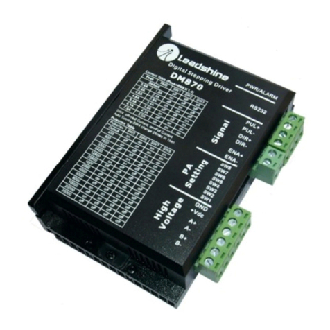
Leadshine Technology DM870 User manual

Leadshine Technology
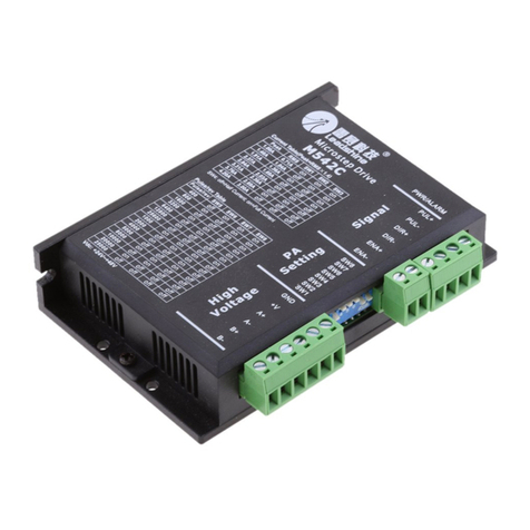
Leadshine Technology M542C User manual

Leadshine Technology
Leadshine Technology DM542 User manual

Leadshine Technology
Leadshine Technology M542 V2.0 User manual

Leadshine Technology
Leadshine Technology CS-D507E User manual

Leadshine Technology
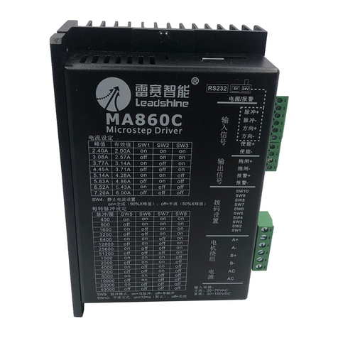
Leadshine Technology MA860C User manual

Leadshine Technology
Leadshine Technology M752 User manual

Leadshine Technology
Leadshine Technology AM882 User manual

Leadshine Technology
Leadshine Technology MA860H User manual

Leadshine Technology
Leadshine Technology MA860 User manual