6
MAINTENANCE 3
It is recommended to perform maintenance 3 after 1.500 operating hours.
The spare parts package 3 contains the following parts:
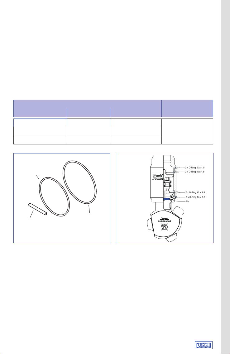
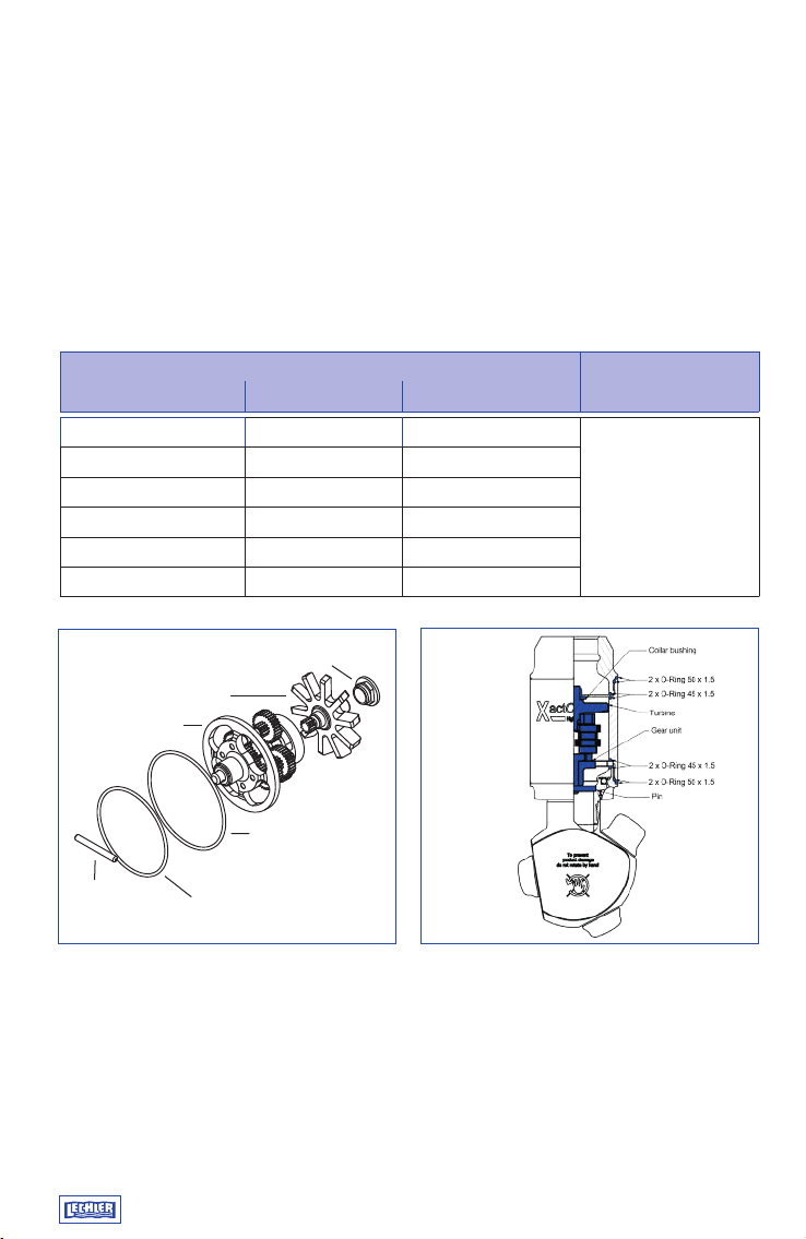
Spare parts package 3
Name Quantity Product number Order number
Pin 1 pc. 5S5.000.K8.00.25.0
5S5.000.1Y.00.70.0
O-ring 45 x 1.5 mm 4 pcs. 095.015.E9.11.53.0
O-ring 50 x 1.5 mm 4 pcs. 095.015.E9.11.54.0
Bearing unit 1 pc. 5S5.000.1Y.00.30.0
O-ring 27.5 x 1.5 mm 1 pc. 095.015.E9.11.55.0
O-ring 31 x 1.5 mm 1 pc. 095.015.E9.08.34.0
O-ring 25 x 1.0 mm 1 pc. 095.015.E9.06.97.0
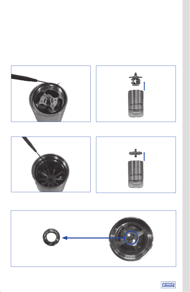
The following steps from this maintenance manual are necessary for carrying out
maintenance 3:
Disassembly of housing Steps 1 – 9
Disassembly of spray head and bearing unit Steps 14 – 18
Correct inspection Steps 19 – 20
Assembly of spray head with bearing unit Steps 21 – 27
Mounting of housing Steps 33 – 36
Assembly of spray head with housing Method A or B
For maintenance 3 the Lechler assem-
bly tool order no. 05S.590.16.00.00.0.
is required.
Tip
1x Pin
Material: PEEK
5S5.000.K8.00.25.0
1x O-ring ø 27.5x1.5mm
Material: EPDM
095.015.E9.11.55.0
1x O-ring ø 25x1mm
Material: EPDM
095.015.E9.06.97.0
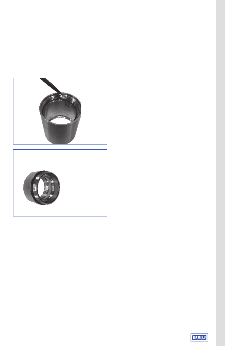
1x Bearing unit
Material: 1.4404
5S5.000.1Y.00.30.0
4x O-ring ø 50x1.5mm
Material: EPDM
095.015.E9.11.54.0
4x O-ring ø 45x1.5mm
Material: EPDM
095.015.E9.11.53.0
1x O-ring ø 31x1.5mm
Material: EPDM
095.015.E9.08.34.0