Lechler XactClean HP Operating and maintenance instructions

Maintenance
Instructions
XactClean®HP

2
1 Introduction 3
2 Disassembly 4
3 Correct inspection 8
4 Reassembly 11
4.1 Reassembly – Method A 14
4.2 Reassembly – Method B 15
CONTENT

3
INTRODUCTION
This manual shows the maintenance for Lechler XactClean®HP tank cleaning nozzle.
Please note: The Lechler assembly tool (Ordering No. 05S.290.30.00.00.0) and the spare
parts package (order No. 5S2.000.1Y. 00.50.0) are required for maintenance.
The assembly tool can be reused. The spare parts package is needed for one time main-
tenance only.
Spray head
Bearing unit
Pin
Gear box Housing
Turbine
Connection piece
O-ring 4x
The spare parts package includes a bearing
unit, a pin and four O-rings.
Description Ordering no.
Bearing unit 5S2.000.1Y.00.24.0
Pin 5S2.000.1Y.00.22.0
O-ring (4x) 5S2.000.6C.00.23.0

Tip
4
To dismantle the XactClean®HP open the housing first.
DISASSEMBLY
1
All threads of the XactClean®HP are
right-hand threads.
To unscrew the housing please use a
suitable flat wrench or a pliers wrench
and a vise with soft jaws.
Either the connection piece or the bea-
ring unit will become loose.
Important: The first part - which has
been loosened - must not be unscrewed
completely. It should remain unscrewed
so that the second part can be loosened.
For this reason, the housing is clam-
ped on the side in the vice - where the
loosened part is located - as shown in
the picture.
23

5
Remove the pin. Remove the O-ring from the other side of
the housing.
The gear unit can be easily removed by
pulling it out.
The O-ring from the other side of the
housing must be removed.
The turbine can now be easily pulled out.
4 5
6 7
8 9
Housing part without gear and turbine
unit.

6
DISASSEMBLY
Remove the O-ring from the bearing unit.
Use both grooves in the spray head
shaft to remove the spray head from the
bearing unit.
It is recommended to use the Lechler as-
sembly tool for disassembling the spray
head. Ordering No. 05S.290.30.00.00.0
Remove the O-ring from the connection
piece.
10 11
12
13

7
Place the ends of the Lechler assembly
tool pin in the grooves of the bearing unit.
Use a suitable spanner or pliers wrench
to unscrew the spray head together with
the Lechler assembly tool.
The coating on the thread of the bearing unit may come o when unscrewing. This is consi-
dered normal, since the thread coating is for single use only.
15
14
16

8
CORRECT INSPECTION
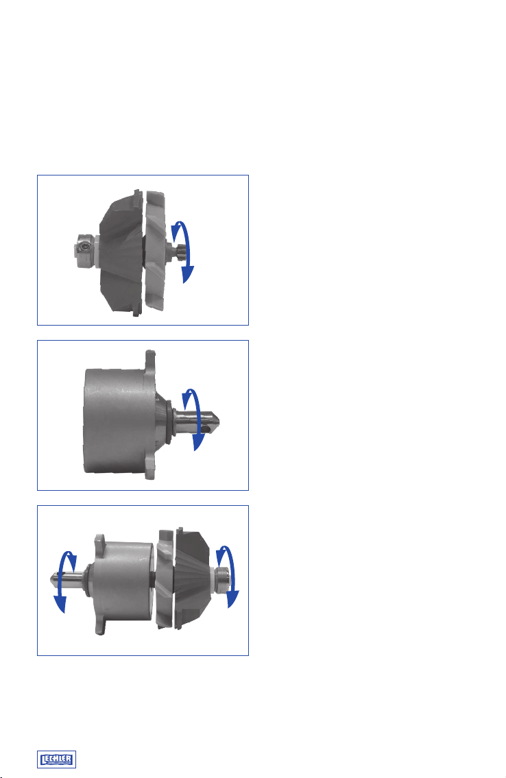
To check the function of the gear unit,
turn the output shaft while holding the
gear unit housing. It is normal for the
rotation to be stagnant. However, the
spindle should be rotatable.
Rotate the beige colored part while hol-
ding the blue one to check the function of
the turbine. The rotation should be smoo-
th with minimal friction. There should be
very little play in the turbine head.
If the turbine cannot be turned by hand
easily or if there is strong wear and tear
of the turbine, it must be replaced.
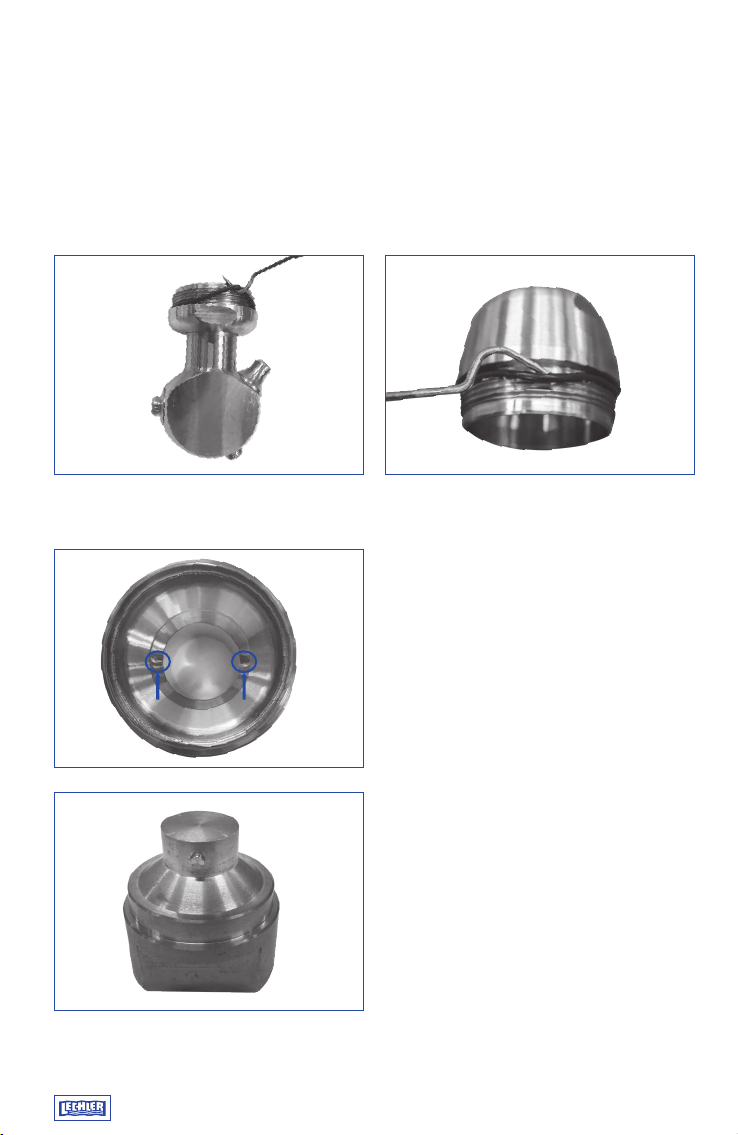
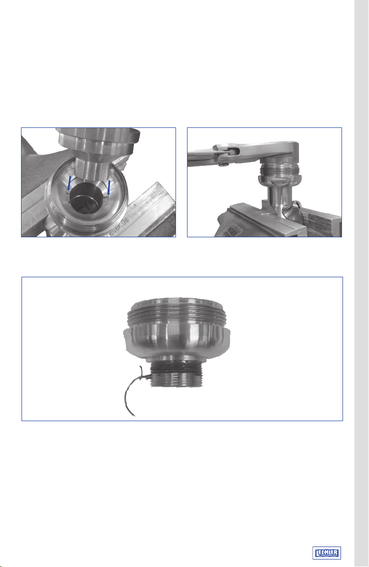
The second and more reliable way to
check whether the gearbox is working
is to insert the turbine unit‘s gear into
the gearbox. The next step is to turn the
spindle of the turbine unit for a few re-
volutions. This should work with minimal
eort and rotate without much eort and
friction.
If it cannot be turned by hand, small
particles, e.g. sand, may have accumu-
lated between the gears. These can be
removed by soaking and rinsing or by
means of an ultrasonic bath. Do not use
excessive force, as this may destroy the
gear unit.
If the gearbox cannot be turned by hand,
it must be replaced.
17
18
19

Tip
9
Description Part number
Turbine unit for type 5S2.95X 5S2.959.T7.00.10.0
Turbine unit for type 5S3.05X 5S3.059.T7.00.10.0
Turbine unit for type 5S3.11X 5S3.119.T7.00.10.0
Turbine unit for type 5S3.18X 5S3.189.T7.00.10.0
Turbine unit for type 5S3.23X 5S3.239.T7.00.10.0
Turbine unit for type 5S3.26X 5S3.269.T7.00.10.0
Gear box 5S2.000.1Y.00.21.0
If the turbine unit or gearbox does
not function properly, it is recommended
to replace the corresponding part with a
new unit.

10
CORRECT INSPECTION
Spray head
Bearing unit
Pin
Gear box Housing
Turbine
Connection piece
O-ring 4x
The spare parts package includes a bearing unit, a pin and four O-rings.
The bearing unit is the most common worn part of the XactClean®HP. (Higher wear is to
be expected, especially at higher pressures above the recommended operating pressure
of 5 bar and particle contaminated cleaning media.)
20
21

11
REASSEMBLY
The Lechler assembly tool is required
to screw the spray head onto the new
bearing unit. The bearing unit should be
tightened with a torque of 20 Nm.
The housing has grooves on each side which dier in size.
The three blades of the turbine unit must
be inserted into the three large grooves of
the housing part.
22
23
24

Tip
12
Insert new O-ring into the O-ring groove
of the housing part.
Insert a new O-ring into the O-ring groove
of the fitting and ensure that the O-ring
on the thread is not damaged.
The connection piece is now screwed
by hand onto the turbine side of the
housing.
REASSEMBLY
The position of the three gear box pins in
the certain grooves must be shown.
It is necessary to turn the output shaft of
the gearbox in order to insert the turbine
gear into the gearbox.
A suitable grease for EPDM can be
used for mounting the O-rings.
25
26 27
28

13
Once the three pins are located in the
grooves, it is possible to assemble a new
O-ring into the O-ring groove.
Push the new pin into the transverse bore
of the output shaft of the gear unit.
To mount the bearing unit with the
housing, the two grooves of the bearing
unit must be aligned with the pin. The pin
must be centered directly in the bore of
the gear unit.
Insert new O-ring into the O-ring groove
of the bearing unit and make sure that
the O-ring on the thread is not damaged.
29 30
32
31

14
REASSEMBLY
Mark the position of the pin with a
permanent marker on the outside of the
housing.
Mark the position of the grooves with a
permanent marker on the outside of the
spray head spindle of the bearing unit.
The two markings are used to position
the bearing unit and the housing in which
the gear unit is located.
The thread of the bearing unit is screwed
into the housing. The markings must be
held in position during screwing.
Continue with step 35 on page 16
33a
33b
33c 33d
There are two ways in which the bearing unit can be assembled with the housing.
Method A

15
Screw the bearing unit into the housing
by hand until a slight resistance is felt. Do
not use excessive force to tighten, the
pin may not be fully inserted into the two
grooves.
Rotate the spray head by hand while blocking the turbine shaft with one finger until the pin
is inserted into the grooves. A „clicking“ sound will be made. The preload of the bearing
unit against the housing must be adjusted by first unscrewing and then screwing it in.
If the pin is locked into the grooves,
screw the bearing unit onto the housing
by hand.
Continue with step 35 on page 16
34a
34b
34c
Method B

16
REASSEMBLY
With the use of a vice and a torque
wrench, the connecting piece is tighte-
ned to a torque of 30 Nm.
Turn the spray head to check that all parts are correctly mounted.
There should be minimal force. It is possible for the rotation of the head to be stationary
but it should rotate.
35
36

Edition 04/20 · 095.009.78.17.90.0 · DE/EN · Subject to technical modification.
Lechler, Inc. · Precision Nozzles · Nozzle Systems
445 Kautz Rd. St. Charles, IL 60174 · Phone: 800-777-2926 · Fax: 630-377-6657
[email protected] · www.lechlerusa.com
LECHLER WORLDWIDE
World Headquarters
Lechler Companies
Sales Oces
Table of contents
Other Lechler Industrial Equipment manuals