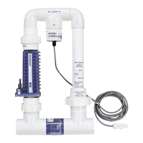
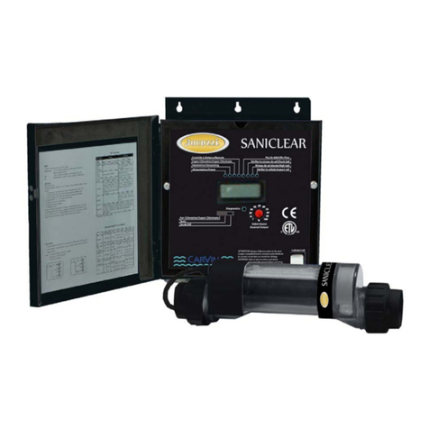
Lectranator Systems 360 User manual

INSTALLATION / OPERATION
MANUAL FOR ALL SRT MODELS
RETAIN MANUAL FOR FUTURE REFERENCE
Controls Bacteria and Algae in Spa and Swimming Pool Waters
MODEL 360 REGISTRATION NUMBER 23160 PEST CONTROL PRODUCTS ACT
(Can treat a maximum of 125,000 litres of swimming pool water.)
MODEL 840 REGISTRATION NUMBER 20151 PEST CONTROL PRODUCTS ACT
(Can treat a maximum of 180,000 litres of swimming pool water.)
Maximum output of hypochlorous acid equivalent to 0.54 kg of free available chlorine per day.
For swimming pools, a minimum of 1 ppm of free available chlorine must be maintained.
For spas, a minimum of 3 ppm of free available chlorine must be maintained.
IMPORTANT
READ THE LABEL AND OPERATING MANUAL BEFORE USING
CL Marketing Inc. 2770 - 24 Avenue NE Calgary, Alberta T1Y 6V7
Salt Chlorine Generator
Domestic
Lect SRT Man ENG 360 840 Final June 2005
08-Oct-2008
2008-2772

Factory Direct Customer Assistance...
HOTLINE: 1.800.661.8179 or 1.403.250.2494
FAX: 1.403.291.1023
Visit Us On The Internet @
http://www.tabex.com
Manufactured for
CL Marketing Inc.
2770 - 24 Avenue NE Calgary, Alberta T1Y 6V7
Installer
Date Installed Model Number
Control Panel Serial Number
Cell Serial Number Pool Gallons
Record The Following Information

Table Of Contents
Important Safety Instructions . . . . . . . . . . . . . . . . . . . . . . . . . . . . . . . . . . . . . . . . . . . . . . . . . . . . . . . . . . . . . . . 1
Specifications . . . . . . . . . . . . . . . . . . . . . . . . . . . . . . . . . . . . . . . . . . . . . . . . . . . . . . . . . . . . . . . . . . . . . . . . . . 2
1 a System Sizing . . . . . . . . . . . . . . . . . . . . . . . . . . . . . . . . . . . . . . . . . . . . . . . . . . . . . . . . . 3, 4
1 b Pool Water Preparation & Charts. . . . . . . . . . . . . . . . . . . . . . . . . . . . . . . . . . . . . 5 - 8
2 a Material Requirements For Installation . . . . . . . . . . . . . . . . . . . . . . . . . . . . . . . . . 9
2 b Control panel & Cell Installation . . . . . . . . . . . . . . . . . . . . . . . . . . . . . . . . . . . . . . . 10
3 a Hi Voltage Wiring . . . . . . . . . . . . . . . . . . . . . . . . . . . . . . . . . . . . . . . . . . . . . . . . . . . . . . 11
3 b General Information . . . . . . . . . . . . . . . . . . . . . . . . . . . . . . . . . . . . . . . . . . . . . . . . . . . . 12
4 a Control Panel Indicators . . . . . . . . . . . . . . . . . . . . . . . . . . . . . . . . . . . . . . . . . . . . . . . 13
4 b Start Up Sequence . . . . . . . . . . . . . . . . . . . . . . . . . . . . . . . . . . . . . . . . . . . . . . . . . . . . 14
5 a Trouble Shooting Model 360 & 840 . . . . . . . . . . . . . . . . . . . . . . . . . . . . . . 15, 16
Section 1 Water Pretest & Preparation
Section 2 Plumbing Requirements
Section 3 Control Panel Mounting & Wiring
Section 4 Start Up & Operation
Section 5 Trouble Shooting
Models: 360 & 840

When installing and using this electrical equipment, basic safety precautions must
always be followed, including the following:
1. READ AND FOLLOW ALL INSTRUCTIONS.
2. Refer problems to qualified personnel. Do not attempt to dismantle or repair. No user serviceable parts.
Warranty void if tampered with.
3. WARNING - to reduce the risk of injury, do not permit children to install or operate this product.
4. WARNING - Risk of electric shock. Connect only to a 110VAC grounding type receptacle protected by a
ground fault circuit interrupter (GFCI). Contact a qualified electrician for installation or if you cannot verify
that the receptacle to be used is protected by a GFCI.
5. WARNING - Do not bury cord. Locate system and cord to minimize abuse from lawnmowers, trimmers and
other equipment.
6. WARNING - To reduce risk of shock, replace damaged cord immediately.
7. WARNING - To reduce the risk of electric shock, do not use with extension cords. Connect only to a
properly installed and located electrical outlet.
8. WARNING - Do not use spas, hot tubs or pools unless all suction grates are installed to prevent body and
hair entrapment.
9. DANGER - To reduce risk of drowning from hair and body entrapment, install suction fitting(s) with a
marked flow rate that equals or exceeds the flow rate on the equipment assembly.
10. Do not install LECTRANATOR unit within an outer enclosure or beneath the skirt of a hot tub or spa.
11. CAUTION - Maintain water chemistry in accordance with manufacter’s instructions.
12. All field-installed metal components such as rails, ladders, drains, or other similar hardware within 3m (10
feet) of the spa or hot tub shall be bonded to the equipment grounding bus with copper conductors not
smaller than No. 8 AWG in the U.S.A. and No. 6 AWG in Canada.
13. Follow all aspects of the local and National Electric Code(s) when installing this product.
14. For outdoor installation, mount the LECTRANATOR Control Panel to ensure the least amount of direct
exposure to rain, direct sunlight or any corrosive environment.
15. Install at least 5 feet from the inside wall of the pool or spa.
16. A green ground wire is fastened to the inside of the Control Panel. To reduce the risk of electrical shock,
connect this ground wire to the grounding terminal of your electrical service or supply panel with a
continuous green or green & yellow striped insulated copper wire, equivalent in size to the circuit
conductor supplying this equipment, but no smaller than No. 12 AWG (3.3mm2).
17. A security screw is provided on the access cover to restrict access to the Control Panel after installation.
Remove screw from access cover prior to installation, insert and tighten screw when installation is
complete.
18. SAVE THESE INSTRUCTIONS.
CAUTION
Failure to follow these instructions can result in fire, explosion, electric shock or electrocution.
Read through and follow these instructions carefully before beginning the installation or start up of the
Lectranator system.
IMPORTANT SAFETY INSTRUCTIONS
1

ALL MODELS INPUT: 115 VAC, 50/60 Hz, 2.5 Amps
220 VAC, 50/60 Hz, 1.3 Amps
Outputs
SRT360 with RC-7 Cell Maximum output of hypochlorous acid equivalent to 0.54 kg of free available chlorine per
day @ 3.5 Amps per 24 hours @ Maximum setting (10)
SRT840 with RC-15 Cell Maximum output of hypochlorous acid equivalent to 0.54 kg of free available chlorine per
day @ 5.0 Amps per 24 hours @ Maximum setting (10)
Flow Rate Ideal: 25US Gallons/min./95 Liters/Min. (on external bypass)
Reverse Polarity Function (Standardin all models)
The Reverse Polarity Function is designed to automatically clean the cell blades, maximizing the cell’s ability to manufacture
chlorine or bromine.
This feature is only enabled when the GREEN CELL ON indicator is displayed. This feature is part of a start up cycle. Thirty
minutes after the Control Panel is energized, a polarity reversal occurs, which cleans the cell. There after, as long as the Control
Panel is allowed to operate continuously without a power interruption, an expected polarity reversal will take place approximately
every 3 hours of main filter pump operation. This setting is not selectable. Since the OUTPUT CONTROL DIAL effects the amount of
time the GREEN CELL ON indicator is displayed, it also has the same effect with regards to the Reverse Polarity Function.
NOTE: Before adding any make-up water to your pool, it is suggested that pretesting the make-up water for high pH, total
alkalinity and calcium hardness will aid in the adjustment of these levels before they become excessive.
If manual cleaning of the cell is required, please refer to page 5 for further details and instructions.
Specifications
2
Automatic Self Cleaning Feature

System Sizing
Use these three formulas to figure your correct water volume:
Rectangular Pool: Length (feet) x Width (feet) x Average Depth (feet) x 7.5 = Total Gallons
Lenght (m) x Width (m) x Average Depth (m) x 1000 = Total Litres
Oval / Round Pool: Diameter (feet) x Diameter (feet) x Average Depth (feet) x 5.9 = Total Gallons
Diameter (m) x Diameter (m) x Average Depth (m) x 790 = Total Litres
Free Form Pool: Average Length (feet) x Average Width (feet) x Average Depth (feet) x 7.5 = Total Gallons
Average Length (m) x Average Width (m) x Average Depth (m) x 1000 = Total Litres
Lectranator’s System Production Capacity
1. Sanitizer Demand / Pool Requirements
The rate at which sanitizer is consumed in any swimming pool depends on the relationship of eight major variables. Since these
variables can vary widely from pool to pool and season to season, precise prediction of the sanitizer demand for any one pool is
difficult. At the end of this section, rules of thumb are provided for Lectranator System Sizing. Given all the variables, should you find
the unit unable to keep up with the sanitizer demand in your pool (assuming it is being operated correctly), we suggest increasing the
output through a larger or multiple units.
THE VARIABLES ARE:
1. Volume and surface area of the pool / spa being sanitized.
2. Average water temperature maintained: As the temperature of the water increases, the sanitizer demand will also increase.
As the temperature of the water decreases, the sanitizer demand will also decrease. When this happens, the output dial
should be decreased to compensate for this lower demand (which will also protect your equipment from excessive levels of
sanitizers).
3. Cyanuric acid level maintained: This chemical, when added to pool water, significantly inhibits chlorine depletion from
exposure to sunlight. Cyanuric acid levels must be maintained between 30 and 100 ppm to ensure that the chlorine being
produced is protected from UV breakdown.
4. Bather load: As the bather load increases, the sanitizer demand will also increase. Heavy uses of the spa (excessive conta-
mination) may require longer recovery times (a return to a minimum of 3 ppm bromine). Recovery time may be reduced by
adding a shock compound to the water.
5. Amount of direct sunlight / UV exposure: Pools exposed to larger amounts of direct sunlight are more vulnerable to
increased sanitizer loss and algae growth. Indoor or screened pools have less sanitizer demand.
6. Exposure to vegetation and airborne debris: Dense landscaping near the pool, along with increased nitrate levels (urine,
bird droppings, fertilizer, well water, etc.) greatly contribute to increased sanitizer demand.
7. Chemical dilution: Virtually all pool chemicals experience dilution through rainfall, adding of fresh make-up water due to evap-
oration, splash-out, filter backwashing, leaks, etc. When freshwater is added, sanitizer demand increases for a brief period.
8. Main filter pump runtime and your pool’s circulation patterns: Sanitizer can only be produced while the main filter pump is
operating. Waterfalls/Fountains and other water features operated by the filter pump can directly effect sanitizer demand. The
main filter pump runtime and/or output dial may need to be increased to satisfy this higher demand.
3
System Sizing For Swimming Pools
Section 1 a

2. Sanitizer Production / System Sizing
While sanitizer demand varies beyond precise prediction, the following “rules of thumb” will assist you in properly selecting the correct
Lectranator model. When unsure, we recommend selecting the larger model versus the smaller model if you desire 100% of your san-
itizing requirements be satisfied with your Lectranator System.
1. A Control Panel with a RC-7 cell, operated at maximum output (3.5 amps), at 3000 ppm salt residual will produce
Sodium Hypochlorite equivalent to 0.545 kg of chlorine per day. This amount of chlorine should satisfy most residential pool
applications, depending on the 8 demand variables for sanitizer.
2. A Control Panel with a RC-15 cell , operated at maximum output (5.0 amps), at 3000 ppm salt residual will produce
Sodium Hypochlorite equivalent to 0.545 kg of chlorine per day. This amount of chlorine should satisfy higher demand applica-
tions, depending on the 8 demand variables for sanitizer.
NOTE: Residual salt levels must be maintained above 2800 ppm and below 3200 ppm.Do not exceed 3200 ppm salt residual or
you will begin to taste the salt in the water! Maintaining constantly high levels of salt and chlorine and/or bromine above recom-
mended range can contribute to corrosion of the pool or spa equipment. Salt levels exceeding the recommended concentration
can be reduced by diluting the spa water with fresh water.
System Sizing For Swimming Pools (Continued)
4
Section 1 a
RC-7
RC-15

STEP 1 - Proper Water Balance Requirements
Proper Lectranator System operation is dependent on proper pool water conditions. Manually balance the pool water chemistry to meet all recommended ranges of
water balance factors below before start-up of Lectranator. From that point forward your Lectranator System will assist you in keeping your water chemistry factors in
balance. Check expiry date of the test kit as the result may be inaccurate if used after that date
Maximum spa water usage temperature is 40 C. Duration in spa water at 40 C should not exceed 15 minutes. For proper sanitation, spa must be completely drained
periodically. The number of days between COMPLETE SPA DRAINAGE is equal to the volume of spa water in litres, divided by 10 times the maximum number of
daily spa users. Refill spa with water and repeat the start-up procedure.
BEFORE START UP MAKE SURE THE POOL WATER MEETS THE FOLLOWING REQUIREMENTS:
ALL WATER BALANCE FACTORS SHOULD BALANCE WITH LANGELIERS SATURATION INDEX. WE RECOMMEND THE TAYLOR K-2005 TEST KIT, OR A
VISIT TOYOUR LOCAL POOL PROFESSIONAL. CHECK EXPIRY DATE OF THE TEST KIT AS THE RESULT MAY BE INACCURATE IF USED AFTER THAT DATE.
Lectranator System Required Ranges (And periods for testing water for these water balance factors.)
CAUTION: Excessive Free Chlorine (> 3.0 ppm) or Free Available Bromine (>5.0ppm) causes corrosion of any metal components in contact with pool/spa water.
Staining and premature failure of heaters, filters, and other metal components will be the result. Do not exceed recommended sanitizer ranges. NOTE: Standard
(DPD reagent) pool water test kits do not read chlorine/Bromine levels above approximately 8.0 ppm residual. Test reagents, at high levels, return to a
clear liquid. AVOID HIGH SANITIZER LEVELS!
STEP 4 - Salt Requirements
It is important that a suggested salt level of 3000 ppm be maintained at all times. Allowing less than 2800 ppm salt may activate a service light. The amount of salt
required depends on the size of the pool. Use of “Tabex” granulated, evaporated, non-iodized blended salt is recommended. Water conditioning pellets can be used
but take longer to dissolve. Use the chart on the next page to determine the amount of salt to add, in pounds or kilos, for a new pool start up. Also test your make up
water for its level of salt and compare it with the charts on the next page. Before adding salt to a pool for the first time, turn your Lectranator off, open your main
drain, then pour salt around the perimeter of the pool.
NEVER add salt directly through the skimmer. Turn device off before adding sodium chloride, sodium bromide and other chemicals, and wait until com-
plete dissolution before turning it on. Use only Sodium Bromide that is registered or scheduled under the Pest Control Products Act..
NOTE: DO NOT allow large amounts of undissolved salt to remain on fresh cementitous pool/spa interior surfaces. Brush vigorously to accelerate salt
dissolving especially in cold water conditions, or in pools with inoperative or no main drains.
Stains From Salt
CAUTION! Generic (bulk) salts have anti-caking additive in them that contains a small amount of Iron. When large quantities of this type of salt are left on the pool
floor to slowly dissolve, this iron content will leave a brown or orange colored stain. We suggest brushing the salt periodically to assist in the dissolving of the salt.
NOTE: Homeowners with water softening equipment, which utilize salt, may already have substantial levels of salt in their drinking water. So before
adding water to your pool, test the level of salt, then determine the amount of salt still
needed to be added to bring the level up to the suggested 3000 ppm level.
Manual Cell Cleaning (Residential Single Cell System
The electrolytic cell has a life expectancy of 2-5 years of use under typical condition of use. When replacing the cell, only use replacement cells having a
label that clearly states that it is:
A) a replacement cell for the chlorine generating device Lectranator Salt Chlorine Generator Model 360, REGISTRATION NUMBER: 23160, PEST
CONTROL PRODUCT ACT, or
B) a replacement cell for the chlorine generating device Lectranator Salt Chlorine Generator Model 840, REGISTRATION NUMBER: 20151, PEST
CONTROL PRODUCT ACT
In normal conditions the Lectranator cell should not require Manual Cleaning. If manual cleaning is required, check water chemistry for possible imbal-
ances or call factory for consultation and use the following procedure.
STEP 1 - Remove the cell by loosening the unions to release.
STEP 2 - Fill a bucket with 1 part muriatic acid or Tabex Grime Away to 4 parts of water. PUT WATER IN BUCKET FIRST!
CAUTION: Always add acid to water never water to acid.
STEP 3 - Submerge the cell and not the flow switch.
STEP 4 - After 10-15 minutes of foaming, remove the cell. Rinse out with fresh water.
STEP 5 - If cell blades still have white crusty scale deposits on them, repeat process, not to exceed 15 minute intervals.
NOTE: DO NOT try to remove any scale from cell blades with any tools. This may scratch or damage the coating on the blades and will void
warranty.
Pool Water Preparation & Monitoring
5
Section 1 b
STEP 2 - Daily Checks
1) Free available Chlorine 1.0-3.0 ppm (pool)
Free Available Bromine 1.0-3.0 ppm (pool)
Free Available Chlorine 3.0-5.0 ppm (spa)
Free Available Bromine 3.0-5.0 ppm (spa)
2) pH 7.2-7.8 ppm
STEP 3 - Monthly Checks
3) Calcium Hardness 200-300 ppm (pool)
Calcium Hardness 150-200 ppm (spa)
4) Total Alkalinity 100-120 ppm
5) Cyanuric Acid 30-100 ppm
6) Salt Residual 2800-3200 ppm
7) Langeliers Index (water balance) + or - 0.3

6
Once a month (or as often as necessary) the cell should be removed and inspected for scale build-up or depris on the cell
blades. If the cell scales continuously, consult the Trouble shooting section in the manual.
1. To prepare the system for servicing:
a. Stop water flow to the Lectranator board by turning off the booster pump and/or the filter
pump. If applicable, shut off AC power to ORP/pH/CL controller and close the flow cell/probe loop valves so as
to isolate the ORP/pH/CL electrodes.
b. Record all models Power Supply Feed Rate knob settings.
c. turn all models Power Supply Feed Rate Knobs to zero(0).
d. Wait for green cell lights (second light from the top) to go out on all models Power supplies.
e. Close the influent and effulent valves on each leg of cells.
f. Be certain to verify that the flow lights (bottom light) on each models Power Supply are on (lit).
g. Unplug DC Cell Cord from the cell(s) to be serviced.
h. Remove the cell or cells from the piping system.
2. To remove debris from cell(s):
a. Flush depris from the cell blades using a garden hose.
3. To remove scale and deposits:
a. Mix four parts water with one part muriatic acid or, four parts of water with one part Tabex®
Grime Away®(4:1).
b. Immerse the cell into the solution. The foaming action is the calcium carbonate being
removed from the cell. Allow cell to remain in the solution for one half hour (maximum).
c. Remove the cell and flush throughly with fresh water. If scale deposits still remain, repeat
procedure using a fresh acid solution.
4. Re-installation of the cell(s):
a. Re-install the cell(s) and tighten unions (hand tight only).
b. Before fitting the DC plug back onto the cell, make sure the DC plug and cell posts are dry.
Push DC plug securely onto cell to prevent water damage.
c. Always double check your connections to ensure that all DC plugs are connected to their designated Cells.
(example: DC plug B2 is connected to corresponding Cell B2, DC plug C1 to Cell C1, etc.)
5. Putting System Back into Operation:
a. Open the influent and effluent valves on each leg of cells. If applicable, re-open the valves to the flow cell or
probe loop and turn AC power back on to the ORP/pH/CL controller.
b. Turn on the system booster pump and/or the filter pump. Adjust flow to 25 US Gallons/min., if necessary. (At
this point, all flow switch lights should be “off”. If not, contact your Lectranator Service Representative.)
c. Reset all the models Power Supply Feed Rate knobs to recorded settings.
NOTE: The flow switches located on each leg of cells are a safety feature of the system. If the
flow lights fail to illuminate(light) when influent and effulent valves are closed, immediatley
turn off power to the entire system, and contact your Lectranator Service Representive.
WARNING: Always add acid to the water. Do not add water to the acid. Wear ALL protective
gear required by local safety regulations.
NOTE:Do not use any sharp object (screwdriver,chisel etc.) to chip scale or depris from the
blades of the Cell. Only the spray from the garden hose nozzle should be used.
Chlorine Cell Inspection and Cleaning Procedure
Section 1 b

Salt Requirements Needed For 3000 PPM
7
Section 1 b
Pool / Spa Volume in US Gallons
0 ppm 5 12 19 25 37 62 125 250 375 500 749
320 ppm 4.5 11 17 22 33 56 112 223 335 446 669
640 ppm 3.9 10 15 20 29 49 98 197 295 393 590
960 ppm 3.4 8.5 13 17 25 42 85 170 255 340 510
1280 ppm 2.9 7.2 11 14 21 36 72 143 215 286 430
1600 ppm 2.3 5.8 8.7 12 17 29 58 117 175 233 350
1920 ppm 1.8 4.5 6.7 9 13 22 45 90 135 180 270
2240 ppm 1.3 3.2 4.7 6.3 9.5 16 32 63 95 127 190
2560 ppm 0.7 1.8 2.7 3.7 5.5 9 18 37 55 73 110
2880 ppm 0.2 0.5 0.7 1 1.5 2.5 5 10 15 20 30
3000 ppm 00 0 0 0 0 0 0 0 0 0
Salt Level
Before Addition 200 500 750 1000 1500 2500 5000 10000 15000 20000 30000
NOTE: ABOVE CHART BASED ON 1 POUND OF SALT ADDED TO 1 MILLION POUNDS OF WATER
(APPROXIMATELY 120,000 GALLONS) WHICH EQUALS 1 PPM OF SALT.
Pool / Spa Volume in Liters
0 ppm 3 6 9 12 15 30 75 150 225 300 360
320 ppm 2.7 5.4 8 11 13 27 67 134 201 268 322
640 ppm 2.4 4.7 7.1 9.4 12 24 59 118 177 236 283
960 ppm 2 4.1 6.1 8.2 10 20 51 102 153 204 245
1280 ppm 1.7 3.4 5.2 6.9 8.6 17 43 86 129 172 206
1600 ppm 1.4 2.8 4.2 5.6 7 14 35 70 105 140 168
1920 ppm 1.1 2.2 3.2 4.3 5.4 11 27 54 81 108 130
2240 ppm 0.8 1.5 2.3 3 3.8 7.6 19 38 57 76 91
2560 ppm 0.4 0.9 1.3 1.8 2.2 4.4 11 22 33 44 53
2880 ppm 0.1 0.2 0.4 0.5 0.6 1.2 3 6 9 12 14
3000 ppm 00 0 0 0 0 0 0 0 0 0
Salt Level
Before Addition 1000 2000 3000 4000 5000 10000 25000 50000 75000 100000 120000
POUNDS OF SALT NEEDED FOR 3000 PPM RESIDUAL
KILOS OF SALT NEEDED FOR 3000 PPM RESIDUAL

Cyanuric Acid / Stabilizer Conditioner
Cyanuric acid, CYA, (also known as stabilizer or conditioner) prevents rapid breakdown of chlorine by sunlight and inhibits the
corrosive effects of chlorine and bromine. Regulations may exist regarding use of Cyanuric acid; please consult your pool profession-
al. Use the chart below to determine the amount of Cyanuric acid needed. Test water with test kit that includes
CYA testing, then use the chart below to determine the amount to add.
POUNDS OF CYANURIC ACID NEEDED FOR 75 PPM RESIDUAL
NOTE: ABOVE CHART BASED ON 1 POUND OF CYANURIC ACID ADDED TO 41,500 POUNDS OF
WATER (5,000 U S GALLONS) WHICH EQUALS 25 PPM OF CYA.
Recommended required Cyanuric Acid levels are 30 - 100 ppm. To add, pour around the perimeter of the pool.
Allow CYA to dissolve and circulate for 24 hours before measuring again.
Pre-dissolving any chemical prior to addition to pool water is advised.
KILOGRAMS OF CYANURIC ACID NEEDED FOR 75 PPM RESIDUAL
Cyanuric Acid Needed for 75 PPM
8
Section 1 b
Pool / Spa Volume in US Gallons
0 ppm 0.12 0.31 0.47 0.62 0.94 1.6 3.1 6.2 9.4 12.5 18.7
12 ppm 0.1 0.26 0.39 0.52 0.79 1.3 2.6 5.2 7.9 10.5 15.7
25 ppm 0.08 0.21 0.31 0.42 0.62 1 2.1 4.2 6.2 8.3 12.5
37 ppm 0.06 0.16 0.24 0.32 0.47 0.79 1.6 3.2 4.7 6.3 9.5
50 ppm 0.04 0.1 0.16 0.21 0.31 0.52 1 2.1 3.1 4.2 6.2
62 ppm 0.02 0.05 0.08 0.11 0.16 0.27 0.54 1.1 1.6 2.2 3.2
CYA Level
Before Addition 200 500 750 1000 1500 2500 5000 10000 15000 20000 30000
Pool / Spa Volume in Liters
0 ppm 0.08 0.15 0.23 0.30 0.38 0.75 1.90 3.80 5.6 7.5 9.0
12 ppm 0.06 0.13 0.19 0.25 0.32 0.63 1.60 3.20 4.7 6.3 7.6
25 ppm 0.05 0.10 0.15 0.20 0.25 0.50 1.30 2.50 3.8 5.0 6.0
37 ppm 0.04 0.08 0.11 0.15 0.19 0.38 1.00 1.90 2.9 3.8 4.6
50 ppm 0.03 0.05 0.08 0.10 0.13 0.25 0.63 1.30 1.9 2.5 3.0
62 ppm 0.01 0.03 0.04 0.05 0.07 0.13 0.33 0.65 1.0 1.3 1.6
CYA Level
Before Addition 1000 2000 3000 4000 5000 10000 25000 50000 75000 100000 120000

NEEDED BY INSTALLER
1) Required amount of salt
2) Hacksaw, Pipe Cutters or Cable Saw
3) Tape measure & Permanent Marker
4) Screwdrivers: Flat head & Phillips head
5) Drill with 6mm (1/4”) masonry-drill
bit for block or stucco
6) Voltmeter - To determine AC
voltage to Control Panel
7) Test kit for Chlorine/Bromine, Calcium
Hardness, pH, Total Alkalinity, and
Cyanuric Acid (stabilizer).
We recommend the
Taylor Technologies®
Model K-2005 Test Kit
8) P.V.C. Glue
9) P.V.C. Cleaner / Primer
10) Assorted P.V.C. Fittings & Pipe
11) Assorted Electrical Hookup
Components
12) Teflon tape or pipe joint compound
SUPPLIED BY LECTRANATOR
1) Residential Installation / Operation
Manual
2) Limited Warranty with Warranty Card
(Must Return)
3) LECTRANATOR Control Panel
4) • Chlorine/Bromine Production Cell
• Flow Detector With Tee
• Cell Unions
5) Salt test strips & vial with mounting
hardware.
Material Requirements For Installation
9
Section 2 a

Control Panel
Using the supplied anchors and screws, the Control Panel should be mounted on a flat, sturdy, vertical surface away from direct
exposure to sunlight. The Control Panel is equipped with a 3.65m DC cell cord and flow detector cord. For ease of installation, please
ensure that both cords connect to the cell and flow detector while still providing slack in each cord for future service. Using a torpedo
level and permanent marker, hold and level the Control Panel on the surface to be mounted and dot each of the (4) mounting holes
with the permanent marker. Using a .25” (.62 cm) drill bit, drill to a depth of 1” (2.5 cm) and install the supplied anchors. The Control
Panel is now ready to receive the (4) mounting screws to secure the installation. DO NOT SHOOT OR PERMANENTLY ATTACH
THE CONTROL PANEL TO THE WALL! This will void warranty, damage the Control Panel and make it virtually impossible to
service without damaging the cover. NOTE: Install at least 5 ft. (1.53m) from the inside wall off the pool or spa.
Control Panel & Cell Installation
10
Section 2 b
NOTE: The cell is a bi-directional flow device. When installing, do not glue or silicone the threads of the unions into the
body of the cell. This will void the warranty. Teflon tape or pipe joint compound is suggested.

STEP 1 - High Voltage Wiring
All electrical equipment must be located five feet or more from closest pool or spa waterline. Use the ground wire provided inside the
Control Panel for grounding. Bond all equipment, including the Control Panel, to earth ground.
STEP 2 - Wire from the sub-panel - Your Lectranator Control Panel is shipped with the voltage selector switch factory set to
230 VAC. If 115 VAC is desired, remove the screw securing the access cover, using a small slotted screwdriver, slide the red voltage
selector switch to the 115 VAC position. The Control Panel will operate at either 50Hz or 60Hz line power. Ensure that the filter pump
AC voltage used matches the Control Panel voltage setting. Improper wiring will damage the Control Panel, which is not
covered under warranty. Connect AC power to the two hookup wires at the bottom of the Control Panel.
STEP 2 a - Control Panel Hook-up - Ensure that the main filter pump circuit breaker is set to OFF. Connect AC from the LOAD
SIDE of the external time clock, Compool/Jandy filter pump relay or on/off switch to the Control Panel so that Lectranator operates
only when the filter pump operates. For flexibility, ease of wiring and making connections, #14 gauge stranded wire is recommended
for interconnection between the external control system and the Control Panel. Wiring diagrams are located on the Control Panel’s,
access cover.
Each Lectranator Salt Chlorine Generator consists of three (3) main components:
1. The CONTROL PANEL converts incoming AC power to a Low Voltage DC current which energizes the Cell.
2. The CELL receives that Low Voltage DC current from the Control Panel, indicated by a GREEN CELL ON
indicator, which initiates the electrolytic process and allows sanitizer to be produced. This process converts
salt (Sodium Chloride) to 100% Pure Sodium Hypochlorite (Liquid Chlorine) which in turn sanitizes your pool.
This processed salt then reverts back to salt and the entire process is repeated.
3. The FLOW DETECTOR ensures adequate flow is present to produce sanitizer. Further, it protects the Cell
from damage caused by insufficient flow. If the flow rate drops below 20 US Gallons/min. (75.6Liters/Min.),
the Control Panel will display a RED FLOW DETECTOR indicator and the CELL ON indicator will display
dark.
a) Chlorine/Bromine Controller Interface - Each Control Panel has a yellow and black pair of wires labeled. “Use with
chlorine controller only”. These can be used to interface with a chlorine/bromine controller. This is a dry-contact input. If an ORP
controller is used, its output voltage (normally 115 VAC) should be wired to the coil contacts of a normally-closed relay or contactor.
The relay contacts are then used only to break the connection between the yellow and black wires on the Control Panel. Remove the
access cover for access to these wires.
NOTE: When an ORP controller is interfaced with a single Control Panel your output dial should be set on 10. Where multi-
ple control panels are interfaced with an ORP controller, consult factory
b) 10A Cell Fuse -On the back of the Control Panel a 10 amp cell fuse is installed into a black fuse holder. This fuse protects the
Control Panel and cell from voltage spikes. If a red service light displays, inspection and possible replacement of this fuse may be
necessary. The Control Panel must be removed from the wall to access this fuse.
High Voltage Wiring
11
Section 3 a
Electronic Component Location: Model 360 & 840
Section 3 b

Control Panel Models
12
Section 3 b
LECTRANATOR MODEL 840
LECTRANATOR MODEL 360
FLOW DETECTOR
CORD
FLOW DETECTOR
FLOW
DETECTOR
TEE DC CELL CORD CELL
UNIONS
LECTRANATOR
CONTROL PANEL
360 840
RC-15
RC-7

Indicator Lights
A. AC ON:
If your Lectranator is wired properly, this indicator will display GREEN whenever the main filter pump is operating. This
indicator ensures that proper incoming AC power is being delivered to the Control Panel. Further, this indicator will display dark whenever the
main filter pump is switched off or power is interrupted. A flashing AC ON light in an indication that either the control panel has failed or that the
system has operated without water flow for 40 minutes or longer.
B. CELL ON:
This indicator will display GREEN whenever the Control Panel is energizing the Cell. While this indicator displays GREEN, rest assured that
your pool is being sanitized with 100% Pure Sodium Hypochlorite (Liquid Chlorine). Except for the OFF position, each time the incoming AC
power is interrupted and then restored to the Control Panel, this indicator will display GREEN for the first 30 minutes of continuous operation
regardless of the Output Control Dial setting. This is a normal START-UP CYCLE whenever the unit is reset by a power interruption. The
Output Control Dial regulates the amount of time the Control Panel switches on and off to energize the Cell. During rest mode this indicator will
display dark.
C. SERVICE:
Normally, this indicator will display dark. This indicator will display RED whenever an abnormal activity exists within the system. If a RED indi-
cator persists, please refer to #8 of the Trouble Shooting Guide on page 16 for further assistance, as one or more of the following conditions
may exist:
a) Low salt level, b) Very cold pool/spa water (below 13°C/55°F), c) Cell plugged with debris or scale deposits
d) DC plug is not pushed tightly onto cell terminals, e) Failing cell, or, f) Blown fuse.
D. FLOW DETECTOR:
Normally, this indicator will display dark. This indicator will display RED whenever insufficient flow is present. Typically, the flow rate drops
below 20 US Gallons/min. (75Liters/Min.). Further, if this indicator is displaying RED, the GREEN CELL ON indicator will display dark. If a
RED indicator persists, please refer to #9 of the Trouble Shooting Guide for further assistance, as one or more of the following conditions may
exist:
a) Flow detector plugged or jammed open with debris, b)Corroded microswitch, c) Flow rate is below 20 US Gallons/min. (80 Liters/Min.)
d) Defective flow detector, e) Control panel not electrically interconnected with pump.
To turn off flow detector light:
1) Turn AC power off (turn pump off), 2) Correct problem (see troubleshooting), 3) Wait 30 seconds to allow panel to reset.
4) Restart system.
Output Dial
This is a percentage timer that regulates the amount of time the system is to produce chlorine/bromine during the filter pump
running cycle. The output is regulated according to the setting of this dial. Each setting has a memory cycle of 22 minutes. The setting of the dial will
determine how long the cell will produce chlorine/bromine and how long it will be in the rest mode. While in the rest mode your cell light will be off to
indicate that no chlorine/bromine is being produced. Below is a chart that indicates the on and off periods of each output setting.
NOTE: Any interruption of power, will cause the current memory cycle to reset itself, when power is restored.
Dial Setting Approx. On-Time Approx. Rest-Time
11 min. 22 min.
22 min. 21 min.
37 min. 16 min.
49 min. 14 min.
511 min. 12 min.
612 min. 11 min.
714 min. 9 min.
816 min. 7 min.
921 min. 2 min.
10 23 min. 0 min.
Model 360 & 840 Control Panel Indicators
13
Section 4 a

Use Of Sodium Bromide Once a bromine pool - Always a bromine pool.
SODIUM BROMIDE (OPTIONAL) - 50 PPM
Where Cyanuric acid is not available or where its use is restricted, bromine can be used as an alternative sanitizer to chlorine.
The Lectranator will convert sodium bromide to bromine in the same way that it converts sodium chloride to sodium hypochlorite.
NOTE: Bromine pools do not require the addition of Cyanuric acid. Typical chlorine stabilizer provides no U.V. protection
for bromine.
To produce hypobromous acid (bromine sanitizer), we recommend initially adding 50 grams of sodium bromide for every 1000 Litres
(4 lbs. for every 10,000 US gallons) of pool water capacity. Thereafter, add 20 grams of sodium bromide for every kilogram of salt
(1 lb. of sodium bromide for every 50 lbs. of salt) added to the pool.
REMEMBER: For the Lectranator System to operate properly, the pool water must contain the recommended level of both salts as
previously specified. (When used, sodium bromide is added in addition to the normal amount of sodium chloride required.)
Before operating the Lectranator System, perform the following steps to ensure proper installation and operation:
A. Turn ON all circuit breakers to the pool equipment.
B. Set the output control dial at position five.
C. Switch on the main filter pump, the following indicators should display....a GREEN AC ON and a RED FLOW DETECTOR. This is
normal. After sufficient flow is detected, the RED FLOW DETECTOR indicator should display dark and approximately 5-10 sec-
onds later, a GREEN CELL ON indicator should display. If this sequence does not occur or any RED indicators display, please
refer to the Trouble Shooting Guide for further assistance.
NOTE: Be sure to monitor the chlorine/bromine level for the next few days and properly adjust the chlorine/bromine output
according to Lectranator’s required levels. DO NOT EXCEED SANITIZER LEVELS REQUIRED!
If an adjustment is required, make the adjustment and allow the pool to react to this change a minimum of 1-2 days. After the 1-2
days expires, retest the pool water and make any further adjustments if necessary.
As the water temperature decreases, the sanitizer demand also decreases.
Lower the Output Control Dial to satisfy this change in sanitizer demand. (When the water temperature drops below 14C (60F), lower
the Output Control Dial, in some cases, set it to the “OFF” position. Because the water temperature is cooler, the sanitizer demand is
lower, it is unnecessary to produce as much sanitizer as normally produced in warmer water. Further, this action protects the Cell from
damage caused by operating below 14C (60F). A non-chlorine shock can be added to the pool until the water temperature increases
above 14C (60F).
As the water temperature increases, the sanitizer demand also increases.
Raise the Output Control Dial to satisfy this change in sanitizer demand.
Model 360 & 840 Control Panel Indicators (Con't.)
14
Section 4 a
Equipment Start Up Sequence
Section 4 b

PROBLEM CAUSE SOLUTION
1. Insufficient sanitizer production.
A. The test kit reagents or test strips are old or expired. A. Retest with new reagents or test strips.
B. The unit is set too low in relation to an increased sanitizer demand. B. Turn up the output dial and/or increase the filter pump run time.
C. The bather load has increased. C. Set the output control dial to #10 and allow the filter pump to operate
24 hours (were applicable remove the “OFF” tripper from the external time
clock) to super-chlorinate / brominate the water.
D. Sanitizer lose due to intense sunlight exposure. D. Check the stabilizer level and add cyanuric acid if needed.
(Refer to the Cyanuric Acid Needed for 75 PPM section, page 7.)
If on bromine, replenish bromine residual.
E. The body of water being sanitized leaks. E. Repair the leak and rebalance the water being sanitized.
(Refer to the Pool Water Preparation section, page 5.)
F. Low salt F. Check the residual salt level and add if necessary. (Refer to the Salt
Requirements Needed for 3000 ppm section, page 6).
2. Scale build-up within the cell.
A. The water being sanitized contains high pH, A. Calculate Langelier’s Index to assure balanced water. (See page 5). Adjust
alkalinity and calcium hardness. the water chemistry and clean the cell (See page 5) Dilute pool water with
fresh water if necessary. Warning- Always add Acid to water never water to
acid.
.
B. The unit is not reversing polarity. B. Send the control panel back to the factory for service.
C. Possible cell failure C. Check with either a 504 or 947 cell tester. Replace the cell if needed.
Refer to #4 of this section.
3. DC plug and cell terminals burned.
A. The cell cord plug is not securely pushed onto A. Ensure that the cell cord plug is pressed completely onto the cell terminals.
the cell terminals allowing moisture to seep into the plug. Check the cell terminals and clean with a dry cloth to remove
all dirt and corrosion.
B. The cell terminals leak. B. Shut off the main filter pump and patch the cell terminal(s) with epoxy putty
and leave the filter pump off for 24 hours.
C. Completely failed cell C. Replace the cell.
4. Premature cell failure. (Requires replacement cell. Normal cell life, if sized and operated correctly, is 3 - 5 years.)
A. The service indicator has been ignored allowing the unit to A. Check and add salt if needed. (Refer to the Salt Requirements Needed
operate (unprotected) at low salt levels. For 3000 PPM section, page 6.)
B. Abnormally high cell usage due to an insufficient cyanuric acid level. B. Check the stabilizer level and add cyanuric acid if needed.
(Refer to the Cyanuric Acid Needed for 75 PPM section, page 7.)
C. Debris in Cell C. Ensure that the strainer union screen is being used. Inspect the cell monthly
and clean debris if required.
5. White flakes in the water.
This occurs when excessive calcium hardness is present in the Monitor the pH and adjust if necessary.
water being sanitized. This should cease after a few days. (Refer to the Pool Water Preparation section, page 5.)
6. No AC ON light.
A. Incoming AC power for the main filter pump is not present. A. Ensure that the main filter pump circuit breaker is set to “ON”.
B. The control panel is damaged. B. Send the Control Panel back to the factory for service.
C. The unit is not wired properly. C. Rewire the unit. (Refer to section 3a, page 11.)
D. Pump is off. D. Make sure pump timer is set properly.
Trouble-Shooting Model 360 & 840
15
Section 5 a

PROBLEM CAUSE SOLUTION
7. No CELL ON light.
A. The unit is in rest mode. A. This is normal.
(Refer to the Output Dial section, page 13.)
B. Red flow detector light B. See # 9.
C. Check the voltage selector switch. C. Ensure that your not powering a 230 VAC Control Panel with 115 VAC.
D. The Control Panel has failed. D. Send the Control Panel to the factory for service.
8. Red SERVICE light.
A. The cell is scaled. A. See # 2.
B. The cell cord is disconnected from the cell. B. Ensure that the cell cord is firmly pressed onto the cell.
C. The 10A cell fuse may be blown. C. Check the 10A cell fuse on the back of the Control Panel and replace
if necessary.
D. Low salt D. Check the residual salt level and add if necessary.
(Refer to the salt requirements needed for 3,000 ppm section, page 6).
E. The unit is not reversing polarity. E. Send the Control Panel back to the factory for service.
F. Possible cell failure. F. Check with either a 504 or 957 cell tester. Replace the cell if
needed. Refer to #4 of this section.
G. Very cold pool water. G. Lower the output control dial setting, even to the “OFF” position, and add
a non-chlorine shock to the pool until the wtaer temperature increases
above 14°C (60° F).
9. Red FLOW DETECTOR light.
A. Water exiting the filter is being diverted away from the inlet A. Increase the flow rate above 15 gallons per minute to activate
of the flow detector. the flow detector.
B. Check the condition of the filter. B. If the filter is dirty, clean the filter to increase the overall flow rate.
C. Check the condition of the strainer union at the inlet C. If it is clogged; remove, clean and reinstall.
side of the flow detector.
D. Ensure that the flow detector is not installed opposite in D. Extract the flow detector and re-install if necessary.
relation to the actual water flow.
E. The Control Panel is not wired properly. E. Rewire the Control Panel. (Refer to section 3a, page 11).
F. The flow detector may have failed. F. Replace the flow detector.
Trouble-Shooting Model 360 & 840 (con’t)
16
Section 5 a

Imported to Canada by
C L MARKETING INC.
2770 -24 Avenue N.E.
Calgary, Alberta, T1Y 6V7
REGISTRATION NO.23160 PEST
CONTROL PRODUCTS ACT
LECTRANATOR Salt Chlorine
Generator Model 360
One360 unit can treat a maximum of
125,000 Liters of swimming pool water.
NOTICE TO USER: This pest control product is
to be used only in accordance with the
directions on the label. It is an offence under
the Pest Control Products Act to use this
product in a way that is inconsistent with the
directions on the label. The user assumes the
risk to persons or property that arises from
any such use of this product.
For swimming pools, a minimum of 1 ppm of
free available chlorine or bromine must be
maintained. For spas, a minimum of 3 ppm
of free available chlorine or bromine must be
maintained.
Controls Bacteria and Algae in Swimming
Pool Waters.
Maximum output of hypochlorous acid
equivalent to 0.54 kg of free available
chlorine per day.
WARNING: Operating the LECTRANATOR
MODEL 360 without water flow through
the cell can cause a build up of flammable
gases which can result in FIRE OR
EXPLOSION
DOMESTIC
READ THE LABEL AND THE INSTALLATION
AND OPERATION MANUAL BEFORE USING.
KEEP OUT OF REACH OF CHILDREN.
PCP STICKER 23160 -SRT360 -ENG FinalJune 2005
This manual suits for next models
3
Table of contents
Other Lectranator Systems Swimming Pool Filter manuals
Popular Swimming Pool Filter manuals by other brands

Jandy
Jandy AquaPure Ei Workbook

Jandy
Jandy SFTM Series Operation / installation instruction

Evoqua
Evoqua BLU-SENTINEL SE Short operating instructions

BIO-LAB CANADA
BIO-LAB CANADA Mineral Springs Pool Pilot Soft Touch 840C Installation and operation manual

Bestway
Bestway FLOWCLEAR 58677 owner's manual

Fiap
Fiap WallSkim Active Slim Series manual