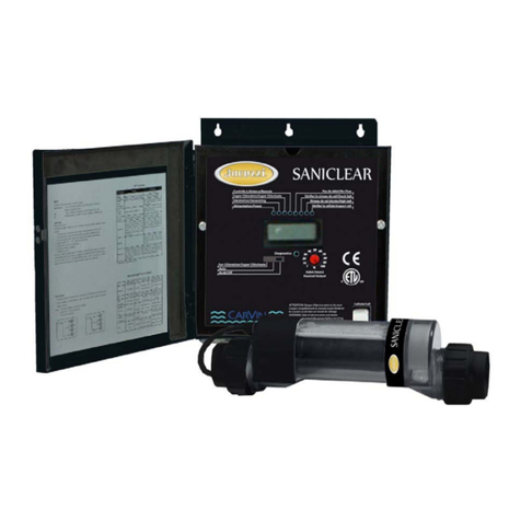
Lectranator Systems ST 60 User manual

2019-5907
2019-11-29
Device
ct
ent
uct.
Device
ct
uct.
Device
ct
uct.
Device
ct
uct.
Imported to Canada by
LECTRANATORSYSTEMSINC.
1034 - 72 Avenue N.E. Calgary,
Alberta, T2E 8V9
Phone: 1.866.517.7584
REGISTRATION NO. 27840 PEST CONTROL
PRODUCTS ACT LECTRANATOR SOFT TOUCH
MODEL ST60 Chlorine or Bromine Generating
One ST60 unit can treat a maximum of
190,000 Liters of swimming pool water.
NOTICE TO USER: This pest control produ
is to be used only in accordance with the
directions on the label. It is an offence
under the Pest Control Product Act to
use this product in a way that is inconsist
with the directions on the label. The user
assumes the risk to persons or property
that arises from any such use of this prod
For swimming pools, a m inimum of 1 ppm of
free available chlorine or bromine must be
maintained. For spas, a minimum of 3 ppm
of free available chlorine or bromine must be
maintained.
Controls Bacteria and Algae in Swimming
Pool Waters.
Maximum output of hypochlorous or
hypobromous acid equivalent to 0.77 kg
of free available chlorine per day
WARNING: Operating the LECTRANATOR
SOFT TOUCH MODEL ST60 without water
flow through the cell can cause a build upof
flammable gases which can result in FIRE
OR EXPLOSION
DOMESTIC
READ THE LABEL AND THE INSTALLATION
AND OPERATION MANUAL BEFORE USING
KEEP OUT OF REACH OF CHILDREN
Imported to Canada by
LECTRANATORSYSTEMSINC.
1034 - 72 Avenue N.E. Calgary,
Alberta, T2E 8V9
Phone: 1.866.517.7584
REGISTRATION NO. 27840 PEST CONTROL
PRODUCTS ACT LECTRANATOR SOFT TOUCH
MODEL ST60 Chlorine or Bromine Generating
One ST60 unit can treat a maximum of
190,000 Liters of swimming pool water.
NOTICE TO USER: This pest control produ
is to be used only in accordance with the
directions on the label. It is an offence
under the Pest Control Product Act to use
this product in a way that is inconsistent
with the directions on the label. The user
assumes the risk to persons or property
that arises from any such use of this prod
For swimming pools, a m inimum of 1 ppm of
free available chlorine or bromine must be
maintained. For spas, a minimum of 3 ppm
of free available chlorine or bromine must be
maintained.
Controls Bacteria and Algae in Swimming
Pool Waters.
Maximum output of hypochlorous or
hypobromous acid equivalent to 0.77 kg
of free available chlorine per day
WARNING: Operating the LECTRANATOR
SOFT TOUCH MODEL ST60 without water
flow through the cell can cause a build upof
flammable gases which can result in FIRE
OR EXPLOSION
DOMESTIC
READ THE LABEL AND THE INSTALLATION
AND OPERATION MANUAL BEFORE USING
KEEP OUT OF REACH OF CHILDREN
Imported to Canada by
LECTRANATOR SYSTEMS INC.
1034 - 72 Avenue N.E.
Calgary, Alberta, T2E 8V9
Phone: 1.866.517.7584
REGISTRATION NO. 27840 PEST CONTROL
PRODUCTS ACT LECTRANATOR SOFT TOUCH
MODEL ST60 Chlorine or Bromine Generating
One ST60 unit can treat a maximum of
190,000 Liters of swimming pool water.
NOTICE TO USER: This pest control produ
is to be used only in accordance with the
directions on the label. It is an offence
under the Pest Control Product Act to use
this product in a way that is inconsistent
with the directions on the label. The user
assumes the risk to persons or property
that arises from any such use of this prod
For swimming pools, a m inimum of 1 ppm of
free available chlorine or bromine must be
maintained. For spas, a minimum of 3 ppm
of free available chlorine or bromine must be
maintained.
Controls Bacteria and Algae in Swimming
Pool Waters.
Maximum output of hypochlorous or
hypobromous acid equivalent to 0.77 kg
of free available chlorine per day
WARNING: Operating the LECTRANATOR
SOFT TOUCH MODEL ST60 without water
flow through the cell can cause a build upof
flammable gases which can result in FIRE
OR EXPLOSION
DOMESTIC
READ THE LABEL AND THE INSTALLATION
AND OPERATION MANUAL BEFORE USING
KEEP OUT OF REACH OF CHILDREN
Imported to Canada by
LECTRANATOR SYSTEMS
INC. 1034 - 72 Avenue N.E.
Calgary, Alberta, T2E 8V9
Phone: 1.866.517.7584
REGISTRATION NO. 27840PEST CONTROL
PRODUCTS ACT LECTRANATOR SOFT TOUCH
MODEL ST60 Chlorine or Bromine Generating
One ST60 unit can treat a maximum of
190,000 Liters of swimming pool water.
NOTICE TO USER: This pest control produ
is to be used only in accordance with the
directions on the label. It is an offence
under the Pest Control Product Act to use
this product in a way that is inconsistent
with the directions on the label. The user
assumes the risk to persons or property
that arises from any such use of this prod
For swimming pools, a m inimum of 1 ppm of
free available chlorine or bromine must be
maintained. For spas, a minimum of 3 ppm
of free available chlorine or bromine must be
maintained.
Controls Bacteria and Algae in Swimming
Pool Waters.
Maximum output of hypochlorous or
hypobromous acid equivalent to 0.77 kg
of free available chlorine per day
WARNING: Operating the LECTRANATOR
SOFT TOUCH MODEL ST60 without water
flow through the cell can cause a build upof
flammable gases which can result in FIRE
OR EXPLOSION
DOMESTIC
READ THE LABEL AND THE INSTALLATION
AND OPERATION MANUAL BEFORE USING
KEEP OUT OF REACH OF CHILDREN

2019-5907
2019-11-29
(PP ST60 & DIG60 Cell Label - RC13 ENGLISH Final)
Cell Model RC-13
This is a replacement cell for the chlorine or bromine generating devices Lectranator Soft Touch Model ST60
REGISTRATION NUMBER 27840, PEST CONTROL PRODUCTS ACT, and Lectranator DigitalModel
DIG60 REGISTRATION NUMBER 27843, PEST CONTROL PRODUCTS ACT. This cell must only be
used on these models of chlorine or bromine generating device.
Read the Label and the Installation and Operation Manual of the chlorine or bromine generating device Lectranator
Soft Touch Model ST60 or Lectranator Digital Model DIG 60 beforeusing.
Lectranator Systems Inc., 1034 –72 Ave N.E., Calgary, Alberta, T2E 8V9
Phone: 1.866.517.7584

2019-5907
2019-11-29
LECTRANATOR SOFT TOUCH
MODEL ST 60
by LECTRANATOR SYSTEMS
INC.
Domestic
Chlorine or Bromine Generating Device
KEEP OUT OF REACH OF CHILDREN
Installation and Operation Manual
MODEL ST60 REGISTRATION NUMBER 27840 PEST CONTROL PRODUCTS ACT
Maximum output of hypochlorous or hypobromous acid equivalent to 0.77 kg of free available chlorine per day
One ST60 Unit Can Treat a Maximum Of 190,000 Litres Of Swimming Pool Water
Controls Bacteria And Algae In Swimming Pool Waters
(For Indoor or Outdoor use)
RETAIN MANUAL FOR FUTURE REFERENCE
CNSF50
IMPORTANT
READ THE LABEL AND THIS MANUAL BEFORE INSTALLING & OPERATING
NOTICE TO USER: This pest control product is to be used only in accordance with the directions on the
label. It is an offence under the Pest Control Product Act to use this product in a way that is inconsistent
with the directions on the label. The user assumes the risk to persons or property that arises from any
such use of this product.
Lectranator Systems Inc. • 2770 - 24 Avenue N.E. • Calgary • Alberta • Canada • T1Y 6V7
Phone: 1.866.517.7584
PP ST60 Residential English Final Nov 2004

1
2019-5907
2019-11-29
Serial Number: # ____________________________
Date of Installation: __________________________
Control Unit
Serial Number: # ____________________________
Installer: ___________________________
Control Unit
Model Number: ST60______________
Cell Model
Number: RC-13
LECTRANATOR SOFT TOUCH
MODEL ST 60
by LECTRANATOR SYSTEMS
INC.
Record The Following Information
Factory Direct Customer Assistance…
HOTLINE: 1.866.517.7584 or 1.403.291.9845
FAX: 1.403.291.1023
Visit Us On The Internet @
http://www.lectranator.com
Manufactured for
Lectranator Systems, Inc.
2770 –24 Avenue N.E. • Calgary • Alberta • Canada • T1Y 6V7
LECTRANATOR SOFT TOUCH
MODEL ST 60
by LECTRANATOR SYSTEMS
INC.
Section 1a –GENERAL PRODUCT INFORMATION

Section 1b –GENERAL PRODUCT INFORMATION
2
IMPORTANT SAFETY INSTRUCTIONS
READ AND FOLLOW ALL INSTRUCTIONS
INSTALLATION AND EQUIPMENT RELATED
Installation of LECTRANATOR SOFT TOUCH MODEL ST 60:
When installing and using your LECTRANATOR SOFT TOUCH MODEL ST 60 Control Box, basic safety
precautions must always be followed, including the following:
1.
Follow all aspects of the local and National Electrical Code(s) when installing your Control Box.
2.
Duringinstallation,mountyourControlBoxtoensuretheleastamountofdirectexposuretorain,gardensprinklerwater,direct
sunlight or any corrosive environment.
3.
DANGER–Riskofelectrical shock. Install Control Box atleast3m(10ft.) for 115VAC Units, from the inside wall ofthe
pool or spa using non-metallic plumbing. 1.5 m (5ft.) minimum distance for 230VAC Units.
4.
Allfield-installedmetal components suchasrails, ladders, drainsorsimilar hardware within3 m(10ft.)ofthe spa orhottub
shallbebondedtotheequipmentgroundingbuswithcopperconductors notsmallerthan 8.4mm²(No.8AWG)inthe U.S.A.
and 6.3mm² (No. 6 AWG) in Canada.
5.
WARNING–Maintain water chemistry in accordance with manufacturer’s instructions.
6.
DANGER–Toreducethe risk ofinjury, donot permitchildrentouse thisproduct.
Children shouldnotusespas, hottubsorpoolswithoutpermanentadult supervision.
Equipment Related
115/230VAC, 50/60 Hz Models (fixed wiring)
1
Awireconnectorisprovided onyour
LECTRANATOR SOFT TOUCH MODEL ST 60
toconnecta minimum 8.4 mm²(No.8AWG)in
the U.S.A. and 6.3mm² (No.6 AWG) in Canada. solid copper bonding conductor between this unit and any metal equipment, metal
enclosures of electrical equipment, metal water pipe or conduit within1.5 m (5ft.) of the unit.
2
Abondingterminal islocatedinside yourLECTRANATOR SOFTTOUCH MODELST60. To reducethe risk ofelectricalshock, this
terminalmustbeconnectedtothegroundingmeansprovidedintheelectricalsupplypanelwithacontinuouscopperwireequivalentsizeto
the circuit conductors supplying your
LECTRANATORSOFTTOUCHMODELST 60
.
3
A disconnection device from the power source, with a contact separation ofatleast3mm(0.12in.)inall poles, must be
incorporated in the fixed wiring for permanently wired units.
4
Theinput voltagetothe
LECTRANATOR SOFT TOUCH MODEL ST 60
mustmatchthe 115/230VAC, 50/60 Hz jumperterminalson
the Circuit board, marked “TRANSFORMER PRIMARY”, shown on Page 5.
SAVE THESE INSTRUCTIONS

Section 1c –GENERAL PRODUCT INFORMATION
3
Table of Contents
LECTRANATOR SOFT TOUCH
MODEL ST 60
by LECTRANATOR SYSTEMS
INC.
Section1 GENERAL INFORMATION
1a Product Information and Contact Numbers....................................................................................1
1b Important Safety Instructions..........................................................................................................2
1c Table of Contents............................................................................................................................3
Section2 INSTALLATION
2a Main Components...........................................................................................................................4
Specifications
2b Control Box Connections......................................................................................................................5
Electrical Connections
Cell Cord and Tri-Sensor Connections
ORP Connections
2c Cell and Manifold Installation .............................................................................................................6
Verification of Flow Switch Protection..........................................................................................6
Section3 OPERATION
3a Key Features –Control Panel.........................................................................................................7
3b Pool Water Preparation...................................................................................................................8
Salt Requirement Chart
Start-Up Procedures........................................................................................................................8
3c Monitoring and Maintenance..........................................................................................................9
Water Chemistry Parameters
Saturation Index
Section4 SERVICE and MAINTENANCE
4a Servicing .........................................................................................................................................10
Control Box
Tri-Sensor
4b Servicing .........................................................................................................................................11
Cell Removal
Cell Maintenance and Cleaning
Filter Backwashing .........................................................................................................................11
4c Parts Explosion......................................................................................................................................12
Section 5 TROUBLESHOOTING
5a Troubleshooting ..............................................................................................................................13
Appendix Diagnostics.......................................................................................................................................14

4
Main Components
Tri-Sensor Assembly
Cell for ST60 = RC13
Union
Soft Touch
Control Box
Flow In
Flow Out
CONTROL BOX
converts incoming
ELECTROLYTIC SUPERCELL
TRI-SENSOR ASSEMBLY
AC power to a Low Voltage DC current,
receives Low Voltage DC current from
ensures that adequate
flow
which energizes the Cell(s). Set the
the Power Circuit Board, which initiates
94.5 L/min (25US Gallons/min)
Control Box
on a vertical surface away
the electrolytic process. This process
minimum;
salt
, 2,8 –3,2 gm/l
from excessive exposure to heat and
converts ordinary table salt (Sodium
(2800–3200 ppm) ideal range; and
moisture. Use the template to mark and
Chloride) to 100% Pure Sodium
water temperatures
, above
drill the (4) mounting holes and insert
Hypochlorite (Chlorine Bleach) or
15.6°C (60
F) are satisfactory to
the screws, leaving a ¼ in. gap. Hang the
Bromine (with the addition of Sodium
preventabusiveconditionsforthe
control box on the screws and level.
Bromide), which in turn sanitizes your
cell to operate. See page 10 for
Remove the cover by following the steps
pool or spa.
instructionstoremoveandinspect
on page 10 to access the mounting
See page 8 for salt requirements.
the tri-sensor assembly.
holes to tighten the screws.
RATINGS:
Input Power: 115VAC (3.0 ACamps) MaximumOutput:Equivalentto0.77kg(1.68lbs)offreeavailablechlorine/day
230 VAC (1.5AC amps) RC-13CELL @ Cell Power Level 3 (8 amps DC)
50/60 Hz Cell Life Expectancy: A minimum of 15,000ampere/hours
Output Power: Cell Power 1 (5.0* DC amps) Agency Approvals:NSF,ETLus,ETLc,CE
Cell Power 2 (6.5* DCamps)
CellPower3(8.0* DCamps)
*Indicates nominal amperage output. The dual axis controller will slightly vary the amps to optimize the power to the cell.
Thecellandtri-sensorarelocatedinaPatentedAutomatic FlowBypassManifoldAssembly. 3.6m(12ft.)of
Celland Tri-Sensor
cords
areprovided withthe unit. Ensurethatthemanifold islocated within that distance from the control box with enough slack to
allow for removal for service or maintenance.
CAUTION:
Itis suggested tolocate the cell downstream ofallother equipmentandonthepool returnlineonlytoavoid over-
saturation conditions of your spa. For applications other than as recommended, contact the factory.
Section 2a –INSTALLATION

Section 2b –INSTALLATION
5
AC Plug
Line In
Electrical Connections Control Box Connections
Autopilot recommends that a licensed electrician or certified electrical contractor perform the electrical connections.
DANGER: ensure that the electrical panel or filter pump circuit breaker is turned OFF before wiring this unit.
Your
LECTRANATOR SOFT TOUCH MODEL ST 60
ControlBoxcomespre-wiredfrom thefactoryfor230VAC (1.5 ampsmax draw)and
canalso operate on 115 VAC,(3.0 ampsmax draw)at 50/60Hz. 1.8m (6ft.)of AClead wires are provided with the unit and arelocated on the
bottom base plate ofthe control box along with the Cell, Tri-Sensor and optional ORP Interface connections.
Convertingto115VAC
isaccomplishedbyaccessingthecircuitboard,rewiring,andattachingtheincludedjumperasshownbelow.
Removethecover(seepage10)toaccessandensure thattheJumperConnections onthecircuitboard marked“TRANSFORMER
PRIMARY” are matched to the LINE IN voltage. Follow all state/local codes for electrical installations.
? An additional jumper is Power Circuit Board
provided with your
Installation Kit for 115VAC. Transformer
Location of the
Input Jumper Connections
230 VAC 115 VAC
INNERCONTROLPANEL FACTORYSETTING WIRING DIAGRAM
Top terminals factory wired –do not disturb.
AC to PCB Bonding 6-pinTri-sensor
Lug connector
#1 #2 #3 #4 #5 #6
Ground Conduit
Lugs connector
provided
(Gr/Yel) (Br) (Bl)
2-pin ORP
Connector
Cell Cord
Connectors
LECTRANATORSOFTTOUCHMODELST60ACLineIN
C
ONTROL BOX BASEPLATE
AC LINE IN
(Wiring diagram also located on inside of cover)
:
For 230 VAC
; Brown (Br) = Line 1, Blue (Bl) = Line 2, Green w/Yellow Tracer (Gr/Yel) = Earth Ground
For 115 VAC
; Brown (Br) = Line, Blue (Bl) = Neutral, Green w/Yellow tracer (Gr/Yel) = Earth Ground
TheACLine INwiringispre-setforconnection tothe
LINESIDE
ofyourtimeclock,electronic controller switch orrelay towork
in conjunction with your circulation pump.
Cell Cord
.
Each Cell Cord contains (2) Banana Plugs that attach to the (2) Banana Jacks on the bottom of the Control Box.
Polaritydoesnotmatter. Theotherendofthe cell cord hasa three-position plug that connects tothe cellinany direction. See page
11 for service instructions.
Tri-Sensor Cord
.
The Tri-Sensor Cord connects tothekeyed6-pinharnessontheControlBoxBasePlate. Theoppositeendof
thecordconnectstothe Tri-Sensor Assembly with alocking ringquick connect. Alignthe grove andkeyway ontheconnectorand
twist the locking ring to ensure a proper connection. Refer to the instructions on pages 10 & 12 for diagrams and additional
instructions.
ORP Connection
.
When an ORP Chemical Controller is interfaced to your
LECTRANATOR SOFT TOUCH MODEL ST 60
, the
ChemicalControllerwill remotely control the SANITIZEROutput. Adjust the output level to0%andconnect the ORP controller tothe 2-pin
connectoronthe Control Box Base Plate. When the ORP isactivated, the output will indicate ON with the display showing 0%.
WARNING:THEORPCONNECTIONSAREDRY CONTACTINPUTS,DONOTENERGIZETHESE
INPUTS! DAMAGETO THE CONTROLBOXWILLOCCURANDWILLVOIDTHE WARRANTY.
Plug
TRANSFORMERPRIMARY
TAB 4
TAB 3
115VAC
TAB 6
TAB 5
TAB 8
TAB 7
115VAC
fffffffffff
TAB 10
TAB 9
TRANSFORMERPRIMARY
TAB 4
TAB 3
TAB 6
TAB 5
230VAC
TAB 8
TAB 7
TAB 10
TAB 9

Section 2b –INSTALLATION
6
CLEAN UNION
SCREEN
REGULARLY
Cell and Manifold Installation
Your Lectranator System is adaptable for use with the 13 blade ( RC-13) cell. The manifold must be located as the last
accessory in the
POOL RETURN LINE
only. For special plumbing configurations, please contact your representative for
assistance in locating the manifold.
Standard Manifold Assembly:
Bypass flow rate should be set at 94.5 L/min (25 US Gallons/min
)
.
Tri-Sensor Assembly
Cell for ST60 = RC13
Union
Flow In
Flow Out
For other plumbing configurations, please contact your representative for assistance.
Verification of Flow Switch Protection:
It is important to
ANNUALLY
inspect and verify the safe and proper operation of the Tri-sensor’s Flow Switch protection
device. We recommend following this procedure to verify that the flow switch is working as designed, which is to halt power
from being sent to the cell in the presence of insufficient flow. A defective Flow Switch could cause serious personal and/or
equipment damage. Using either a GOLF BALL or small plastic wrap (saran wrap, food wrap or zip lock bag), block off flow
to the upper portion of the manifold by placing the golf ball in the strainer screen union or by wrapping the strainer screen with
the plastic wrap and placing it back in the union and tightening. Operating the system on with this blockage should detect a
FLOW obstruction, indicated on the digital display and activating a red flashing CHECK SYSTEM light. Once this protection
feature has been verified, remove the plastic wrap or golf ball, replace the strainer screen and resume operation. Turn the
output dial to OFF and contact the factory if the flow switch protection is not working properly.
Golf Ball Plastic Wrap
OR
Union

7
Key Features
The
Control Panel Display
provides a
series ofcontrol buttons for
OUTPUT
level,
OUTPUT
Pool P i l o t ™
Soft Touch
BOOST
mode and
SETUP
functions, with
FLOW-OK SERVICE CELL POWER
diagnostic indicator lights for FLOW-OK, 100%
1
SALT and SERVICE.
Two additional
2
indicator lights show the selected setup
CELL POWER
and
REVERSING
cycle.
50%
SALT 3
OK REVERSING
The LECTRANATOR SOFT TOUCH MODEL
BOOST SHORT
LOW NORMAL
ST 60 SANITIZER
OUTPUT
level is adjustable from
LONG
0% (OFF) to 100 %(MAX). Press the
Up/Down Arrow
to set the desired output level. Little adjustment
0%
ADD
Concealed Set Up Button
is needed once the initial setting is established.
The selected output level will remain steady when the system is at rest and will begin pulsing when the system is producing the
SANITIZINGagent.
Note:The
LECTRANATOR SOFT TOUCH MODE
LST60doesnottestforSANITIZERlevelsnorautomatically
adjust to maintain a desired SANITIZER level. This is done by periodically testing the water and adjusting the output levels up or
down, asneeded.
The LECTRANATOR SOFT TOUCH MODEL ST 60 is designed with an
AUTOMATIC TEMPERATURE COMPENSATION feature
,
whichautomaticallyadjuststheoutputlevelsettingbaseduponchangesinseasonalwatertemperaturesonly. Thisuniquefeatureconveniently
compensates for warm (more SANITIZER needed) or cold (lessSANITIZER needed) water conditions.
The
SETUP Mode
allows the user to program the
CELL POWER
and
REVERSING
cycle. To enter Setup Mode, press and hold
the concealed Setup button (small bubble adjacent totheSalt OKlight) until the
CELLPOWER
light begins flashing. The
LECTRANATOR
SOFTTOUCHMODELST60
isseton
“2 “
from the factory. Use the Up/Down Arrows to change the Cell Power setting ifneeded. Adjust
the OUTPUT level at the new setting to maintain proper sanitizer levels.
WARNING:
Operating on
“ 1 “
reduces cell power but extends cell life;
“ 3 “
increases cell power but reduces cell life.
Pressing the Setup Button once more will go to the
REVERSING
cycle. The LECTRANATOR SOFT TOUCH MODEL ST 60 is set on
“
NORMAL
”fromthefactoryforidealcell life. Use theUp/DownArrowstoselectthe Reversingcycle. Forconditionssuchasextremelyhigh
calciumlevelsorconditionsthatcancause thecelltoscalequickerthantheself-cleaning cyclecancontrol,change thesettingto“
SHORT
”.
Foroptimumwaterchemistry balanceaccording totheSaturation Index,seepage 9,youcanchangethe REVERSING cycle to
“
LONG
”. Pressingthe setup button oncemorewillleave the Setup Mode andsavethe programmedCell Powerand Reversing
settings. Test your water chemistry parametersmonthly and compare to the Saturation Index.
WARNING
:ChangingtheReversingcycletoSHORTwillalsoreducecelllife. However,operatingthecellunderscaledconditions
on “Normal” or “Long” is more detrimental to the life of the cell and changingthe Reverse cycle is suggested.
The
BOOSTButton
activates the Boostlight whenitispressedonce. This lightindicates that the system isinBoost Mode andwill
produce the SANITIZINGagent for 24 hours. The SANITIZINGagentcan beproduced for72-hours bypressingand holdingthe
BOOST button for 5-secondsfrom the Boost-Off position. This iscalledthe
Super-BoostMode
. A flashing Boost light indicates
thatthesystemhassuccessfullyenteredthismode. Ineithermode,theSANITIZINGagentisproducedcontinuously,throughoutthe
normalOn/OffcyclesofthepumpandthroughoutallpowerlinedisturbancesatanoutputSANITIZINGlevelof100% regardlessof
thenormalSANITIZINGoutputlevelsetting. Thesystemwilldiscontinue operationofthe Boost mode orSuperBoost modeifthe
boostbuttonispressedoncemoreandreturntothe normal SANITIZINGoutput level setting. The pool/spa pump must beturnedon
during the whole boost cycle. Do not let the pump run on a timer during that period.
The
SALT
light indicatesthesalt level inthe water. The salt level should be maintained between2.8–3.2g/l (2800–3200 ppm).
TheSALT-
OK
light willbeonifthis saltlevelisachieved. If the salt level drops below 2.5 g/l (2500 ppm),the SALT-
LOW
light
willturn onand the system will continue toproduce theSANITIZINGagent. Ifthesaltlevel dropsbelowa safe value, theSALT-
ADD
light will turn on and the system will no longer continue to produce the SANITIZINGagent.
(
NOTE
Maintaining high saltlevelsabove recommendedrangecancontribute tocorrosionofpool/spaequipment. Saltlevels
exceedingtherecommendedconcentrationcanbereducedbydilutingthepool/spawithfreshwater.) SeeAppendix(page14)to
determine your saltlevel.
The
FLOW-OK
lightturns onwhenthereissufficientflow. Any problemswithinsufficient waterflowisindicatedbyaFlow-OK
light that is not on and a Flashing Service Light (single flash pattern).
The
SERVICE
light flasheswhenservice isneeded. A Single flash pattern oftheservice lightindicates insufficientwaterFlow. A
Double flash pattern of the service light indicates high cell volts and low amps, which is caused by a scaled or failing cell or a
loose/defectivecellcord. ATripleflashpatternoftheservicelightindicateshighcellvoltsandlowamps,whichiscausedbyafailed
power supply. A Quadruple flash pattern of the service light indicates a failed tri-sensor orcord.

Section 3b –OPERATION
8
Salt Requirements
Pool Water Preparation
Itisimportant that withtypical pools, a salt residual of2.8–3.2g/l(2800 to 3200 ppm)be maintained atall times for peakefficiency.
NOTE:
Maintaining high salt levels above recommended range can contribute to corrosion of pool/spa equipment. Salt levels
exceeding the recommended concentration can be reduced by diluting the pool/spa with fresh water.
Theamount ofsalt required depends on the size ofthe pool and the present salt level. Asthe salt isbeing added, we recommend
runningthecirculationpumpcontinuallyfor24hourswiththe maindrainopened. Brushingthesalttowardsthebottommaindrain
will assist in the dissolve rate and prevent possible staining with certain types of salt.
We recommend the use of
TABEX LectraClor™ or LectraClor Plus™
blended salt products . These products do not contain
Yellow Prussiate of Soda (YPS) or Iodine. Iodine and YPS can cause a localized tint to the water or brown staining on the
cementitious finishifallowedtorestundissolvedonthefinishforextendedperiodsoftime.
LectraClor Plus™
is blendedwiththe
properamountofstabilizertomaintainaproperlevel withintherecommended range whenaddedaccording tothesaltchart onthe
box.
Granular Salt, Table Salt,Solar Salt orWaterConditionerPelletscanalsobeusedbutwillhave different dissolve rates. Ifthesalt
youusecontains IodineorYPS,constantbrushingwillhelpthe dissolve rateandpreventstaining duetotheadditivesinthesalt.
Ensure thatthe salt you use contain a minimum purity of 99% Sodium Chloride (NaCl).
NOTE: Do not use Rock Salt due to its high levels of impurities.
TESTYOURWATERFORSALTLEVELFIRST
with the provided salt test strips,
and then use the chart below to determine the amount of salt to add.
SALT REQUIREMENT CHART
KILOS (LBS.) OF SALT NEEDED FOR 3000 PPM RESIDUAL
SALT Level
Before Addition
Pool Volume in Liters (US Gallons)
3,780
(1,000)
9,430
(2,500)
18,900
(5,000)
28,300
(7,000)
37,780
(10,000)
56,700
(15,000)
75,600
(20,000)
113,600
(30,000)
0 ppm
11.3 (25)
28 (63)
57 (126)
85 (175)
113 (252)
175 (378)
227 (504)
340 (756)
500 ppm
9.5 (21)
24 (53)
48 (106)
73 (147)
95 (212)
145 (318)
191 (424)
286 (636)
750 ppm
8.6 (19)
22 (48)
43 (96)
66 (133)
86 (192)
130 (288)
173 (384)
259 (576)
1000 ppm
7.7 (17)
19 (43)
39 (86)
54 (119)
77 (172)
116 (258)
155 (344)
232 (516)
1500 ppm
5.9 (13)
15 (33)
30 (66)
41 (91)
59 (132)
89 (198)
119 (264)
178 (396)
2000 ppm
3.6 (8)
9.5 (21)
19 (42)
30 (56)
38 (84)
57 (126)
76 (168)
113 (252)
2250 ppm
2.7 (6)
7 (15)
14 (30)
19 (42)
28 (60)
41 (90)
54 (120)
81 (180)
Note:
Theabovechartis based on120 gramsofsaltadded to1000 Liters ofwater(1lb. per 1,000 gallons) toincrease your salt
residual 120-ppm.
Start Up Procedures
Keep the Output Setting on your
LECTRANATOR Soft Touch Model ST 60
on 0% (OFF) until you get your water clear, blue and properly balanced.
1.
After balancing your water chemistry according to the Water Chemistry Parameters shown onpage 9, add the proper
amountofsalt(seeSaltRequirement Chartabove)andcirculate 24-hourspriortostartingyour
LECTRANATOR SOFT TOUCH MODEL ST 60
.
2.
Thefollowingday,turnyourOutputLevelto50%andoperatenormally. Test waterasrequiredtoconform withlocalhealth
code. Raise or lower output control setting asneeded.
3.
Once your Output Level has been established, you will only need to adjust your level according to increased bather usage.

Section 3c –OPERATION
9
Monitoring and Maintenance
Water Chemistry Parameters
-
VERY IMPORTANT NOTE! Your
LECTRANATOR SOFT TOUCH MODEL ST 60
is designed to provide SANITIZER on
a daily basis. We recommend the following water chemistry ranges and periodic checks to monitor your systems efficiency. Always follow all local and state
requirements. Check the expiry date of the test kit as test results may be inaccurate if used after that date.
CHLORINE/BROMINEREQUIREMENTS:
During Peak SANITIZERDemand (rainy season orheavy batherusage) itmaybe
necessarytoincreaseyourSANITIZERlevelbyincreasingyourOutputLevelsettingand/orpumpruntime. Conversely,duringLow
SANITIZERDemand,youcandecreaseyour Output Leveltoa lowersetting. Forextremely HeavySANITIZERDemandortoboost
your SANITIZER levels quickly, you can
Boost
the system or supplement with a Potassium Monopersulfate based shock. If the
water is clear but is difficult getting a bromine residual using DPD or test strips, we recommend using an OTO test kit.
NOTE: Duringcold-waterconditions,below60ºF,SANITIZERdemandisreducedsignificantly.
Forcolderclimateregions
with sustainedloworfreezing temperatures, contact your local pool professional for proper pool winterizing instructions.
WARNING:
Excessive chlorine levels can cause corrosion damage to stainless steel rails, ladders, heater heat exchangers, light
faceplatesandothermetallicequipment. Avoidoversaturationofchlorinelevels. Theoutputsettingmustbesufficiently highto
maintaintherecommendedchlorineresidualintheswimmingpool/spawater. Provincialand/ormunicipalregulationmustbe
followed.
pH:
WhenpHlevelsfallbelow the recommended range,SANITIZERisusedupquicklyandcanbedamagingtoequipment. ForpH
levels higherthan the recommended range,SANITIZERbecomeslesseffective and workshardertokeep your poolsanitized.
ImproperpHalsocontributestothestrongsmell,redeyes,dryitchyskinandbrittlehairconditionsassociated with“toomuch
Chlorine”.
CALCIUM HARDNESS AND TOTAL ALKALINITY:
Your
LECTRANATOR SOFT TOUCH MODEL ST 60
provides 100% pure
sodium hypochlorite and does not affect the calcium hardness or total alkalinity levels. Maintain and balance only as needed.
CYANURICACID(STABILIZER/CONDITIONER):
Thischemicalgoesbyeithertradenameandallowsthechlorineresidualto
last longerbyprotecting itfrom the UVdegradation ofthe sun. WithlowornoCyanuric acid itispossible forthechlorine tobe used
upasquickly asit enters the pool. Check and maintain your cyanuric acid levels atthe same timeasyour salt level, as these tend to
depleteatthe same rate. Regulations may exist regarding the useofcyanuric acid; pleaseconsult yourlocal authority.
NOTE:For
Bromine or indoor pools, it is not necessary to add stabilizer.
SALTRESIDUAL:
Your
LECTRANATOR SOFT TOUCH MODEL ST 60
works most efficiently with salt levels between2.8–3.2g/l
(2800-3200 ppm). Ifit falls below 2.8g/l (2800 ppm),determine the salt level and adjust according tothe SALTREQUIREMENT. Lowsalt
willcausepremature deteriorationofthe Cell blades. Maintaining high saltlevelsaboverecommended range cancontributetocorrosionof
pool/spa equipment. Salt levels exceeding the recommended concentration canbe reduced bydilutingthepool/spa withfresh water.
BROMINE RESIDUAL:
Along with the normal Salt level, add 0.45 kg (1 lb) Sodium Bromide (NaBr) per 7500 L (2000 gallons) of
water Your
LECTRANATORSOFTTOUCHMODELST60
willnowgenerateBrominetopurifyyourpool. Maintain yourbrominelevel
bycheckingyoursaltlevel. Onceyoursaltfallsbelowtherecommendedrange,wesuggestyouadd0.45kg ( 1 lb)sodium bromide with every
22.5 kg (50 lbs) of salt added. Always use a registered or scheduled source of sodium bromine..
SATURATIONINDEX(Si):
aformulausedtoensurethatyourtotal waterchemistry does notfallintoascale formingorcorrosive
condition. Either condition can cause premature damage t o the Cell, equipment and cementitious finish. Have your water
professionally testedperiodically according tothe Saturation Index oruse this chart todetermine your water balance.
Si = pH + TF + CF + AF –Constant
Temperature
TF
Calcium Har dness
CF
Total Alkalinity
AF
TDS
Constant
15.6C
60F
0.4
150
1.8
75
1.9
0 –1000
12.1
18.9C
66F
0.5
200
1.9
100
2.0
1001 - 2000
12.2
24.4C
76F
0.6
250
2.0
125
2.1
2001 - 3000
12.3
28.9C
84F
0.7
300
2.1
150
2.2
3001 - 4000
12.4
34.4C
94F
0.8
400
2.2
200
2.3
4001 - 5000
12.5
39.4C
103F
0.9
600
2.4
250
2.4
5001 - 6000
12.6
Test your water for pH, Calcium Hardness, Total Alkalinity and TDS levels. Use the equivalent Factor in the Si equation.
Si = +0.3; balanced Si above + 0.3; scaling, staining or cloudy water conditions.
Si below -0.3; corrosive to metals, etches/deteriorates plaster finishes or skin irritating conditions.
DO NOT add pool/spa chemicals directly to the skimmer. This may damage the cell.
Saturation Index: ± 0.3 pH of saturation
Visual Cell Inspection for wear, scale or debris
Total Alkalinity: 100 –120 PPM (pool & spa)
Cyanuric Acid: 30 –100 PPM (pool & spa)
Monthly Checks:
Calcium Hardness: 200 –300 PPM (pool) 150-200 (spa) Salt Residual:: 2800 –3200 PPM
1.0 –3.0 PPM(pool)
1.0 –3.0 PPM (pool)
3.0 –5.0 PPM (spa)
3.0 –5.0 PPM (spa)
7.2 –7.8
Daily Checks:
Free Chlorine:
Or Bromine:
Free Chlorine:
Free Bromine:
pH:

Section 3c OPERATION (cont’d)
10
Inner Metal
Cover
Section 4a –SERVICE and MAINTENANCE
Additional notes:
a)
Forpropersanitation,spamustbe completelydrainedperiodically. ThenumberofdaysbetweenCOMPLETESPADRAINAGEisequal
to the volume of spa water in liters, divided by 10 times the maximumnumber of daily spa users.
b)
Maximum spa usage temperature is 40°C (104°F). Duration inspa water at40°C should not exceed 15minutes.
c)
Heavyuseofthespa(excessivecontamination)mayrequirelongerrecoverytimes(Areturntoaminimumof3ppmchlorine/bromine).
Recovery time may be reduced by adding a shock compound to the water.
d)
Hot weather, heavy pool usage, and rain may require a higher output to maintain proper sanitizer residual.
CONTROL BOX
Thereare littleserviceablepartsontheLECTRANATOR SOFTTOUCHMODELST60 ControlBoxexceptthefuses. ForanyotherproblemswiththeControlBox,
please contact the Factory or Authorized Dealer/Service Center.
To remove the Control Box Cover and access the fuses, follow these steps.
DANGER: TURN OFF THE POWER FROM THE CIRCUIT BREAKER BEFORE SERVICING THIS UNIT.
Control Circuit Board
Wire Harness Connection
InsideTopCover
Loosen (4) knobs Lift off coverand disconnect Remove (3)screws and Access is gained to
(you do notneed to) wire harness (Control Circuit liftoffmetalcover. electricalconnections,
(remove these). board removes with cover). fuses,and pump/aux
relay.
TRI-SENSOR ASSEMBLY
TheTri-sensorassemblytestsfor Flow,SaltandWatertemperatures. Aminimumflowrateof94.5L/min(25USGallons/min)isrequired toactivate
theflowswitch. Asthewaterflowclosesthepaddle,amagnetactivatesamicroswitch toverifyproperflow. TheSaltsensorprotectsagainstlowsalt
levels and the temperature sensor protects against cold water temperatures. Both ofwhich can contribute to accelerated cell failure.
Note:Theuseofhighstrengthmagnetdevicesinthecloseproximity
ofthe tri-sensor can cause the flow switch to readincorrectly.
Remove the Tri-Sensor as follows (with pump off):
RemovebothscrewsfromthesidesoftheTeeAssembly.
With the aid of large Channel-lok® (or similar) pliers, firmly
griptheTri-Sensorassemblyandmovebackandforth
while removing the Tri-Sensor from the tee.
Inspect the thin metalic paddle for erosion and straightness.
Takecarenotto twistortweakthispaddle,which cancause
inaccurate flow readings.
Inspectthesaltsensorbladesforscaleanddebrisandclean
ifnecessary. See page 13 for cleaning instructions. Follow
the directions forManual Cell Cleaning.
Checkthetri-sensorassemblyforanydamagetotheplastic
housing and replace ifneeded.
LECTRANATOR SOFT TOUCH
MODEL ST 60
Front of Unit
Top Cover
F3
F2
F1
directional
Arrow
screw(s)
oneoneachside
Fuse Location and Ratings
F1
F2
Main AC Power Fuse
Control Panel Circuit Board Fuse
6 Amps 250 VAC
3 Amps 250VAC
F3
Cell Fuse
20 Amps 250 VAC

Section 4b –SERVICE and MAINTENANCE
11
13
RC-
Cell
TheCell isinstalledwithUnionsoneachendofthecelltoallow quickandeasyremoval. Loosentheunions andremovethecell
from the plumbing.
Side View of Cell and Unions
VISUAL CELL INSPECTION:
ThetitaniumCellblades,seeninsidetheCellbody,shouldbestraightandclearofanydebrisbetweentheblades. Your
LECTRANATOR
SOFTTOUCHMODELST60
isdesignedtoautomaticallyself-cleancalciumscalebuild-upwithintheCell. However,imbalancedwater
chemistryandcertainconditionscancause aheavier scalebuildupthatexceedstheself-cleaningcapabilityandwouldneedtobecleaned
manually by the method described below.
Periodically inspect both ends of the cell.
A White Flaky or Crusty build-up on the
edgeorbetweenthebladeswillprematurely
depletethelifeofthe cell. Immediately End View ofcell
clean the cell and determine the cause of LookingattheTitaniumBlades
scaling. See Troubleshooting Section, page 13.
MANUAL CELL CLEANING:
With the Cell removed as described above, use a high-pressure hose nozzle to spray off as much loose, soft scale and debris as
possible. Anyremainingcalciumscalecanbetreatedwitha mixtureofone(1)part Muriatic Acidintofour(4)partswater. Mixthe
solutioninacontainerhighenoughtocovertheCellblades.Youmayalsouse
TABEXLectraClean™ (
non-fuming/pre-mixed)cell
cleaner, per label directions.
Remove the Cell cord and immerse the Cell so that the blades are completely covered in the solution for up to 15 minutes. An
effervescencesactionindicatesthecalcium isbeingneutralized andcleaned. Drainthecell,flush withfreshwaterandre-inspect.
Repeattheimmersionifnecessary. Oncethe cellhasbeencleanedandrinsed;itmaybere-installedin-line. BESURETHATTHE
CELL“PINS” ARECLEANAND DRYBEFOREATTACHINGTHE DCCORDFROM THEPOWERSUPPLY.
WARNING:
ALWAYS ADD ACID TO WATER, never water to acid.
Whenreplacingthecell,onlyusereplacementcellshavingalabelthatclearly statesthatitisareplacementcellforthechlorineorbromine
generating device Lectranator Soft Touch Model ST60,REGISTRATIONNUMBER 27840, PESTCONTROLPRODUCTS ACT.
WARNING: ALWAYS ADD ACID TO WATER, never water to acid.
NEVERUSE ANYSHARPORMETALLICOBJECTSTOREMOVESCALE. Scrapingorscratchingthetitaniumblade’s
edge or surface will allow chemicalattack of the blade, cause premature failure ofthe Cell and will void your warranty.
Hacksaw Blades Screwdrivers Forks Knives
FILTER BACKWASHING:
The Control Panel Output setting must be set to 0% (OFF) when backwashing the filter.

Section 4c –SERVICE and MAINTENANCE
12
13
ll RC-
Ce
Parts Explosion
Manifold Assembly: Manifold Union w/Strainer:
(#941) (#19065)
TRI-SENSOR
UnionNut
Union O-Ring (#19014)
Strainer (#19064)
CELL w/ UNIONS
MANIFOLD
UNION
w/Strainer
MANIFOLD BASE w/Check Valve
Electrolytic Cell:
(Cell Unions and Cord ordered separately)
12ft. (3.6m) Cell Cord (# 952-1)
Union O-Ring (#19013)
Nut Half only (2 pcs) for 2 in. (50mm) S x S Union Thread Half Only for 2 in. (50 mm) S x S Union
Tri-Sensor Assembly:
(Cord Ordered Separately)
DirectionalFlowIndicator
View of locking
Quick connect heads
12ft.(3.6m) Tri-Sensor Cord (# 956-DIG)
Tri-Sensor O-Ring (#19028)
Temperature Sensor Post
Salt Sensor Blades
Direction of Water Flow
Flow Paddle
Tri-Sensor
(#909-GO1.5)

Section 5a –TROUBLESHOOTING
13
TROUBLESHOOTING
PROBLEM CAUSE SOLUTION
1)
Insufficient SANITIZERProduction.
A)
The test kit reagents or test strips are oldor expired. A)Retest with new Reagents or Strips.
B)
The unit is set too low in relation to SANITIZER demand. B) Turn up the outputsetting.
C)
The circulation run time is insufficient. C) Increase your pump run time.
D)
The bather loadhas increased. D) Same solution as (B) or add a Non-Chlorine Shock
containing Potassium Monopersulfate to supplement.
E)
The body of water beingsanitized leaks. E) Repair the leak and rebalance as needed.
F)
Low Salt. F) Check the residual salt level and adjust as needed.
G)
“Cell Power” selection not matched to the cell installed. G) Follow the SET UP procedures to match the cell, see page 7.
H)
SANITIZER loss due tointense sunlight H) Check your stabilizer level and adjust ifneeded.
2)
Scale Build-up within the Cell.
A)
The water being sanitized contains highpH, total A) Calculate Saturation Index to assure balanced water.
alkalinity and calciumhardness levels. Adjust chemicals and clean the Cell. See pages 9 & 11.
(Cell scales within 2 –3 weeks)
B)
Power Supply not reversing polarity. B) Contact the factory for Warranty Status/Procedures.
(Cell constantly scales within 3 –5 days)
3)
DC Plug and Cell Terminals Burned.
A)
The Cell terminals are wet due to a leaking cell body. A) Contact the factory for Warranty Status/Procedures.
B)
The Cell plug is not securely pushed onto the cell B) Ensure the Cell cord plug is pressed completely onto the
terminals, allowing moisture to seep intothe plug. Cell terminal. Check the terminals and clean with a dry
cloth to remove all dirt and corrosion.
4)
Premature Cell Failure (Requires Replacement Cell).
A)
Abnormally high Cell usage due toan insufficient A) Check the stabilizer level and adjust to recommended levels.
Stabilizer (Cyanuric acid) level.
B)
Excessive Scale/Debris inthe Cell. B) See Section 2 above.
C)
“Cell Power” selection not matched to the Cell installed. C) Follow the SETUP procedures to match the cell, see page 7.
5)
White Flakes in theWater.
A)
This occurs when excessive calciumhardness is A)Visually inspect Cell for scale build-up and clean the cell as
present. Usually due to waterchemistry imbalance. described on page 11. Adjust your water chemistry.
6)
No Power to the Control Box.
A)
Internal Fuse blown. A) Check and replace fuse. See page10.
B)
Circuit Breaker tripped. B) Check the power going to the Control Box. Reset the
Circuit Breaker.
7)
SERVICE Light (Single RED Flash and Flow-OK light off).
A)
Tri-Sensor Defective. A) Contact the factory for Warranty Status/Procedures.
B)
Insufficient Flow Min. (94.5 L/min) (25 US Gallons/min) B) Ensure your Filter and Cell are clean of debris.
Check all valves that might divert flow away from the cell.
8)
SERVICE Light (Double RED Flash)(SANITIZER is producing).
A)
High Cell Volts with Low Amps A) Check cell for calcium build-up or scale deposits.
Cell is depleted and needs replacement.
Cell cord is loose or defective. Ensure that the cord is firmly
attached to the cell. Check the Banana Plug connections.
9)
SERVICE Light (Triple RED Flash)(SANITIZER production halted).
(Microprocessor version V1.4 or older)
A)
High Cell volts with Extremely Low Amps. A) Heavily scaled cell or failed cell.
(Microprocessor version V1.5 or newer)
A) Improperly wired or failedPower Supply. A) Ensure voltage input matches wiring connection (page5).
10)
SERVICE Light (Quadruple RED Flash)(SANITIZER is producing).
A)
Tri-sensor or tri-sensor cord is looseor defective. A)Inspect and tighten orreplace.
11)
LOW SALT Light activated (SANITIZER is producing) .
A)
Salt level Low (below 2,5 g/l(2500 ppm)). A) Check with Salt test strips or meter and adjust asneeded.
12)
ADD SALT Light activated (SANITIZER production halted).
A)
Salt level extremely low (below 2.0 g/l(2000 ppm)). A) Check with Salt test strips or meter and adjust asneeded.
13)
Unable to set output to a high level.
A)
Temperature is too low (below 15.6C (60F)). A) The LECTRANATOR SOFT TOUCH has limited output to protect thecell.

Appendix –BUILT-IN DIAGNOSTICS
14
BUILT-IN DIAGNOSTICS
The
LECTRANATORSOFTTOUCHMODELST60
Control Boxcontainsawaytodisplaya diagnosticreportonits operation. Itallowsthe
usertoviewthe saltconcentration,thewatertemperature,andtheElectrolytic Cellvoltageand amperage. This isprovided for atechnician to
evaluatetheperformanceoftheLECTRANATORSOFTTOUCHwithouttheneedforspecialequipment. Thevaluesaremeasuredbycounting
the number of flashes of the lights, as described below.
To access and interpret the diagnostics, follow this procedure:
Tostartthediagnostic procedure,pressandholdboth the UPandDOWNbuttonsatthesame time. Holdthem presseduntil
the output display lights go out, leaving just the bottom light illuminated (about 5 seconds).
1.
The
first
value tobedisplayedisthe
salt concentration
inPartsPerMillion(PPM). This value ismeasured bycounting
thenumber offlashes ofthe top 3 lights. In the case ofsalt, the top light isnot used, the next to the top flashes the 1000’s
digit and the third light flashes the 100’s digit in ppm.
Example: 2 flashes/pause/8 flashes/pauseRead: 2,800 PPM
2.
The
second
valueisthe
watertemperature
indegreesFahrenheit. Whenthisis displayed,thesecondlightfromthe
bottom ison. Thetop light flashes the 100’s digit, the next the 10’s digit and the next the units of temperature.
Example: 8 flashes/pause/6 flashes/pauseRead: 86 Degrees F
3.
When the
third
light from the bottom is on, the
cellvoltage
isdisplayed. The top light is not used. The second light
flashes the 10’s digit and the third the units of voltage.
Example: 2 flashes/pause/8 flashes/pauseRead: 28 Volts
4.
When the
fourth
light isonthe
cellcurrent
inamperes isbeing displayed. The top lightdisplays the 10’s digit (not
normally used), the next the units and the third the tenths of amps.
Example: 5 flashes/pause/5 flashes/pauseRead: 5.5 Amps
The diagrams below summarize the built-in diagnostic displays.
SALT TEMPERATURE VOLTS AMPS
x100
F x10 A
x1000ppm x10
F x10 V x1 A
x100 ppm x1
F x1 V x0.1A
(Amps)
(Salt)
(Temperature)
(Volts)

******************************
This label transcript service is offered by the Pest Management Regulatory Agency to provide
efficient searching for label information. This service and this information do not replace the
official hard-copy label. The PMRA does not provide any guarantee or assurance that the
information obtained through this service is accurate, current or correct, and is therefore not
liable for any loss resulting, directly or indirectly, from reliance upon this service.
Table of contents
Other Lectranator Systems Swimming Pool Filter manuals