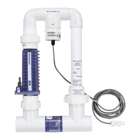
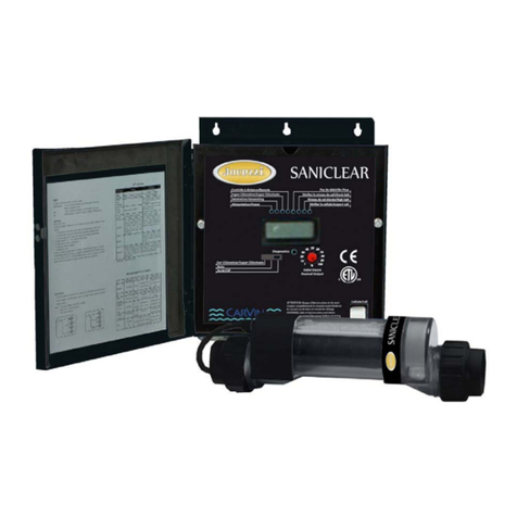
Lectranator Systems Soft Touch Pool Pilot ST840C User manual

2019-5907
2019-11-29
Pool Pilot™
Soft Touch
by LECTRANATOR SYSTEMS
INC.
Commercial
Chlorine Generating Device
Installation and Operation Manual
MODEL ST840C REGISTRATION NUMBER 27476 PEST CONTROL PRODUCTS ACT
Maximum Output Equivalent To 0.91 Kg. Of Free Available Chlorine Per Day
One ST840C Unit Can Treat a Maximum Of 190,000 Litres Of Swimming Pool Water
Controls Bacteria And Algae In Swimming Pool Waters
(For Indoor or Outdoor use)
RETAIN MANUAL FOR FUTURE REFERENCES
C NSF50
IMPORTANT
READ THE LABEL AND THIS MANUAL BEFORE INSTALLING & OPERATING
Notice to User: This pest control product is to be used only in accordance with the directions on the label. It is an
offence under the Pest Control Products Act to use this product in a way that is inconsistent with the directions on the
label. The user assumes the risk to persons or property that arises from any such use of this product.
Lectranator Systems Inc. • 1034 - 72 Avenue N.E. • Calgary • Alberta • Canada • T2E 8V9
PPST Commercial English May 2003 Cdn TEMP2

1
2019-5907
2019-11-29
Serial Number: # ____________________________
Date of Installation: __________________________
Control Unit
Serial Number: # ____________________________
Installer: ___________________________
Control Unit
Model Number: ST840C ____
Cell Model
Number: CC-15
Pool Pilot™
Soft Touch
by LECTRANATOR SYSTEMS
INC.
Record The Following Information
Factory Direct Customer Assistance…
HOTLINE: 1.866.517.7584 or 1.403.291.9845
FAX: 1.403.291.1023
Visit Us On The Internet @
http://www.lectranator.com
Manufactured for
Lectranator Systems, Inc.
1034 –72 Avenue N.E. • Calgary • Alberta • Canada • T2E 8V9
Pool Pilot™
Soft Touch
by LECTRANATOR SYSTEMS
INC.
Section 1a –GENERAL PRODUCT INFORMATION

Section 1b –GENERAL PRODUCT INFORMATION
2
IMPORTANT SAFETY INSTRUCTIONS
READ AND FOLLOW ALL INSTRUCTIONS
INSTALLATION AND EQUIPMENT RELATED
Installation of all Pool Pilot™ Soft Touch models:
When installing and using your Pool Pilot™ Soft Touch Control Box, basic safety precautions must always be
followed, including the following:
1.
Follow all aspects of the local and National Electrical Code(s) when installing your Control Box.
2.
Duringinstallation,mountyourControlBoxtoensuretheleastamountofdirectexposuretorain,gardensprinklerwater,direct
sunlight or any corrosive environment.
3.
DANGER–Risk ofelectrical shock. Install Control Box atleast3m(10’) for 115VAC Units, from the inside wall ofthe
pool or spa using non-metallic plumbing. 1.5 m (5’) minimum distance for 230VAC Units.
4.
Allfield-installedmetalcomponents suchasrails,ladders, drains orsimilarhardware within3m(10’)ofthespaorhottubshall
bebonded tothe equipment grounding buswithcopperconductorsnotsmallerthan8.4mm² (No.8AWG)inthe U.S.A. and
6.3mm² (No. 6 AWG) inCanada.
5.
WARNING–Maintain water chemistry in accordance with manufacturer’s instructions.
6.
DANGER–Toreducethe riskofinjury,donotpermitchildrentousethisproductunlesstheyarecloselysupervised atall
times. Children shouldnot use spas, hot tubs or pools without permanent adult supervision.
Equipment Related
115/230VAC, 50/60 Hz Models (fixed wiring)
1
Awire connector is provided onyour
Pool Pilot
™SoftTouch to connecta minimum8.4 mm² (No. 8 AWG)in the U.S.A. and
6.3mm²(No.6AWG)inCanada.solidcopperbondingconductorbetweenthisunitandanymetalequipment,metalenclosuresof
electrical equipment, metal water pipe or conduit within1.5m (5’) of the unit.
2
Abondingterminal is locatedinside your
PoolPilot
™SoftTouch. To reduce the riskofelectricalshock, thisterminal mustbe
connectedtothegroundingmeansprovidedintheelectricalsupplypanelwithacontinuouscopperwireequivalentsizetothe
circuit conductors supplying your
PoolPilot
™Soft Touch.
3
Adisconnectiondevice fromthe powersource, witha contactseparation ofatleast3mm(0.12”) inall poles, must be
incorporated in the fixed wiring for permanently wired units.
4
Theinputvoltagetothe
Pool Pilot
™SoftTouch must matchthe 115/230VAC, 50/60 Hz jumperterminalson the Circuitboard,
marked “TRANSFORMER PRIMARY”, shown on Page5.
SAVE THESE INSTRUCTIONS

Section 1c –GENERAL PRODUCT INFORMATION
3
Table of Contents
Pool Pilot™
Soft Touch
by LECTRANATOR SYSTEMS
INC.
Section1 GENERAL INFORMATION
1a Product Information and Contact Numbers....................................................................................1
1b Important Safety Instructions..........................................................................................................2
1c Table of Contents............................................................................................................................3
Section2 INSTALLATION
2a Main Components...........................................................................................................................4
Specifications
2b Control Box Connections......................................................................................................................5
Electrical Connections
Cell Cord and Tri-Sensor Connections
ORP Connections
2c Cell and Manifold Installation .............................................................................................................6
Verification of Flow Switch Protection ..........................................................................................6
Section3 OPERATION
3a Key Features –Control Panel.........................................................................................................7
3b Pool Water Preparation...................................................................................................................8
Salt Requirement Chart
Start-Up Procedures........................................................................................................................8
3c Monitoring and Maintenance..........................................................................................................9
Water Chemistry Parameters
Saturation Index
Section4 SERVICE and MAINTENANCE
4a Servicing .........................................................................................................................................10
Control Box
Tri-Sensor
4b Servicing .........................................................................................................................................11
Cell Removal
Cell Maintenance and Cleaning
Filter Backwashing .........................................................................................................................11
4c Parts Explosion......................................................................................................................................12
Section 5 TROUBLESHOOTING
5a Troubleshooting ..............................................................................................................................13
Appendix Diagnostics.......................................................................................................................................14

4
AUTOPILOT
SANITIZING SYSTEMS
Main Components
Tri-Sensor Assembly
CC-15 Cell(s)
Ball Valve
CheckValve
13.8 kpa
2 lb. Spring
Flow In Flow Out
Soft Touch
Control Box
CONTROL BOX
converts incoming
ELECTROLYTICSUPERCELL TRI-SENSOR ASSEMBLY
ACpower to a Low Voltage DCcurrent, receives LowVoltage DCcurrent from ensures that adequate
whichenergizesthe Cell(s). Set the the Power Circuit Board, which initiates
flow
, 5.6 m³/hr (25gpm) minimum;
ControlBox
ona vertical surface away theelectrolyticprocess.Thisprocess
salt
, 2,8 –3,2gm/l
fromexcessiveexposuretoheatand convertsordinarytable salt(Sodium (2800–3200 ppm)ideal range; and
moisture. Use the template to mark and Chloride)to100% Pure Sodium
water temperatures
,above
drill the (4) mounting holes and insert Hypochlorite (Chlorine Bleach) or 15.6°C (60
F) are satisfactoryto
thescrews, leavinga¼” gap. Hang the Bromine (withtheaddition ofSodium preventabusiveconditionsforthe
control box onthe screws and level. Bromide), which inturnpurifies your cell to operate. See page 10 for
Removethe coverbyfollowingthesteps pool or spa. instructionstoremoveandinspect
onpage 10 to access the mounting See page 8 for salt requirements. the tri-sensor assembly.
holes to tighten the screws.
RATINGS:
Input Power: 115VAC (3.0 AC amps) MaximumOutput:Equivalent to 0.91 kg (2.00 lbs) of free available chlorine/day
Aminimumof40,000ampere/hours
230 VAC (1.5AC amps) CC-15CELL @ Cell Power Level 3 (8 amps DC)
50/60 Hz Cell Life Expectancy:
Cell Power 1 (5.0* DC amps) Agency Approvals:NSF, ETL us, ETL c, CE
Cell Power2(6.5*DCamps)
Cell Power3(8.0*DCamps)
*Indicates nominal amperage output. The dual axis controller will slightly vary the amps to optimize the power to the cell.
Thecellandtri-sensorarelocatedina Patented AutomaticFlowBypassManifoldAssembly. 3.6m(12’) of
CellandTri-Sensor
cords
areprovided withtheunit. Ensurethatthemanifoldislocatedwithin thatdistancefromthecontrol boxwith enough slack to
allow for removal for service or maintenance.
CAUTION:
Itissuggestedtolocate the celldownstream ofallotherequipment and onthe pool return lineonly toavoid over-
saturation conditions of your spa. For applications other than as recommended, contact the factory.
Section 2a –INSTALLATION
OutputPower:

Section 2b –INSTALLATION
5
AC Plug
Line In
Electrical Connections Control Box Connections
Autopilot recommends that a licensed electrician or certified electrical contractor perform the electrical connections.
DANGER: ensure that the electrical panel or filter pump circuit breaker is turned OFF before wiring this unit.
Your
PoolPilot
™SoftTouch ControlBoxcomespre-wiredfromthefactoryfor230VAC (1.5ampsmaxdraw)andcanalso operate
on 115 VAC, (3.0amps max draw)at50/60Hz. 1.8m (6’) ofAClead wires are provided with the unit and are located onthe bottom
base plate of the control box along with the Cell, Tri-Sensor and optional ORP Interface connections.
Convertingto115VAC
isaccomplishedbyaccessingthecircuitboard,rewiring,andattachingtheincludedjumperasshownbelow.
Removethecover(see page10)toaccessandensurethattheJumperConnectionsonthecircuitboardmarked“TRANSFORMER
PRIMARY” are matched to the LINE IN voltage. Follow all state/local codes for electrical installations.
? An additional jumper is Power Circuit Board
provided with your
Installation Kit for 115VAC. Transformer
Location of the
Input Jumper Connections
230 VAC 115 VAC
INNERCONTROL PANEL FACTORYSETTING WIRING DIAGRAM
Top terminals factory wired –do not disturb.
AC to PCB Bonding 6-pinTri-sensor
Lug connector
#1 #2 #3 #4 #5 #6
Ground Conduit
Lugs connector
provided
(Gr/Yel) (Br) (Bl)
Pool Pilot AC Line IN
ACLINEIN
(Wiring diagram also located on insideofcover)
:
2-pin ORP
Connector
CONTROL BOX BASE PLATE
Cell Cord
Connectors
For 230 VAC
; Brown (Br) = Line 1, Blue (Bl) = Line 2, Green w/Yellow Tracer (Gr/Yel) = Earth Ground
For 115 VAC
; Brown (Br) = Line, Blue (Bl) = Neutral, Green w/Yellow tracer (Gr/Yel) = Earth Ground
TheACLineIN wiringispre-setfor connectiontothe
LINESIDE
ofyourtime clock, electronic controller switch orrelay to work
in conjunction with your circulation pump.
Cell Cord
.
Each Cell Cord contains (2) Banana Plugs that attach to the (2) Banana Jacks on the bottom of the Control Box.
Polaritydoesnotmatter. The otherendofthecellcord hasathree-positionplugthatconnectstothecell inany direction. See page
11 for serviceinstructions.
Tri-Sensor Cord
.
TheTri-SensorCord connectstothekeyed6-pinharnessontheControl BoxBasePlate. Theoppositeendof
thecordconnectstothe Tri-Sensor Assemblywithalockingringquickconnect. Alignthegroveandkeywayontheconnector and
twist the locking ring to ensure a proper connection. Refer to the instructions o n pages 10 & 12 for diagrams and additional
instructions.
ORP Connection
.
WhenanORP Chemical Controller isinterfaced toyour
PoolPilot
™Soft Touch,theChemicalController
willremotelycontroltheSANITIZEROutput. Adjust theoutputlevelto0%and connectthe ORPcontrollertothe2-pinconnector
on the Control Box Base Plate. When the ORP is activated, the output will indicate ON with the display showing 0%.
WARNING:THEORPCONNECTIONSARE DRYCONTACTINPUTS,DONOTENERGIZETHESE
INPUTS! DAMAGETO THE CONTROLBOXWILLOCCURANDWILLVOIDTHE WARRANTY.
Plug
TRANSFORMERPRIMARY
TAB 4
TAB 3
115VAC
TAB 6
TAB 5
TAB 8
TAB 7
115VAC
TAB 10
TAB 9
TRANSFORMERPRIMARY
TAB 4
TAB 3
TAB 6
TAB 5
230VAC
TAB 8
TAB 7
TAB 10
TAB 9

Section 2b –INSTALLATION
6
Cell and Manifold Installation
YourLectranatorSystem isadaptable for use witha CC-15cell. The manifold must be located asthe lastaccessoryinthe
POOL
RETURNLINE
only. Forspecialplumbingconfigurations,please contactthefactoryforassistanceinlocatingthemanifold.
Standard Manifold Assembly:
By pass flow rate should be set at 94.5 lpm (25 gpm).
Tri-Sensor Assembly
CC-15 Cell(s)
Ball Valve#1
Ball Valve#2
13.8 kpa.
2 lb Spring
Check Valve
To Pool Return
For other plumbing configurations, please contact the factory for assistance.
Verification of Flow Switch Protection:
Itisimportanttoannuallyinspectandverifythesafeandproperoperation oftheTri-sensor’s FlowSwitch protection device. We
recommendfollowingthisproceduretoverifythattheflowswitchisworkingasdesigned,whichistohaltpowerfrombeingsentto
the cell in the presence of insufficient flow. A defective Flow Switch can cause serious equipment damage.
Totest, turn the output dial to“0%”. Slowly,throttleorcloseballvalve#1untilflowtothe cell(s)isreduced tolessthan15
gallonsperminute. DONOTCOMPLETELY CLOSEVALVE #1! Within amatterofONE(1)TOTWO(2)seconds,this
flowobstructionshouldbeindicated onthedigitaldisplayandactivatearedflashing“CHECK SYSTEM” light. Assoonas
thisprotectionfeaturehasbeenverifiedasfunctioning properly,re-establishflowtothecell(s)byreturningballvalve#1toits
originalflowsetting. ThesystemshouldIMMEDIATELYresumenormaloperation. Iftheflowswitch protectionisNOT
working properly, turn AC power off to the entire system IMMEDIATELY and consult your representative or Authorized
Service Centre.

7
Key Features
The
Control Panel Display
provides a
series ofcontrol buttons for
OUTPUT
level,
OUTPUT
Pool P i l o t ™
Soft Touch
BOOST
mode and
SETUP
functions, with
FLOW-OK SERVICE CELL POWER
diagnostic indicator lights for FLOW-OK, 100%
1
SALT and SERVICE.
Two additional
2
indicator lights show the selected setup
CELL POWER
and
REVERSING
cycle.
50%
SALT 3
OK REVERSING
The
Pool Pilot™
Soft Touch SANITIZER
BOOST SHORT
LOW NORMAL
OUTPUT
level is adjustable from 0% (OFF)
LONG
to 100 %(MAX). Press the
Up/Down Arrows
to set the desired output level. Little adjustment
0%
ADD
Concealed Set Up Button
is needed once the initial setting is established.
Theselectedoutputlevelwillremainsteady whenthesystemisatrest and willbegin pulsing whenthe system isproducingthe
SANITIZINGagent.
Note:The
Pool Pilot
™
SoftTouch
doesnottestfor SANITIZERlevelsnorautomaticallyadjustto
maintaina desired SANITIZERlevel. Thisis donebyperiodicallytestingthe waterand adjustingthe outputlevelsup or
down, asneeded.
ThePoolPilotSoftTouchisdesignedwith an
AUTOMATICTEMPERATURECOMPENSATIONfeature
,which automatically
adjusts the output level setting based upon changes in seasonal water temperatures only. This unique feature conveniently
compensates for warm (more SANITIZER needed) or cold (less SANITIZER needed) water conditions.
The
SETUP Mode
allows the user to program the
CELLPOWER
and
REVERSING
cycle. To enter Setup Mode, press and hold
theconcealed Setupbutton(smallbubble adjacenttothe SaltOKlight) untilthe
CELLPOWER
light begins flashing. The
Pool
Pilot
™Soft Touchisset on
“2“
from the factory. Use the Up/Down Arrows tochange theCellPowersetting ifneeded. Adjust the
OUTPUT level at the new setting to maintain proper sanitizer levels.
WARNING:
Operating on
“ 1 “
reduces cell power but extends cell life;
“ 3 “
increases cell power but reduces cell life.
Pressing the Setup Button once more will go to the
REVERSING
cycle. The
PoolPilot
™SoftTouch is set on“
NORMAL
”from
thefactoryforideal celllife. UsetheUp/DownArrowstoselecttheReversingcycle. Forconditionssuchasextremelyhighcalcium
levels orconditionsthatcancausethecelltoscale quickerthanthe self-cleaningcyclecancontrol, changethesettingto“
SHORT
”.
For optimum water chemistry balance according to the Saturation Index, see page 9, you can change the REVERSING cycle to
“
LONG
”. Pressing the setup button once more will leave the Setup Mode and save the programmed Cell Power and Reversing
settings. Test your water chemistry parametersmonthly and compare to the Saturation Index.
WARNING
:ChangingtheReversingcycletoSHORTwillalsoreducecelllife. However,operatingthecellunderscaledconditions
on “Normal” or“Long” is more detrimental to the life of the cell and changingthe Reverse cycle is suggested.
The
BOOSTButton
activates theBoost light whenitispressedonce. This lightindicates that thesystemisinBoost Mode andwill
produce the SANITIZINGagent for 24hours. The SANITIZINGagent canbeproduced for72-hours by pressingand holding the
BOOST button for 5-secondsfrom the Boost-Off position. This iscalledthe
Super-BoostMode
. A flashing Boost light indicates
thatthesystemhassuccessfullyenteredthismode. Ineithermode,theSANITIZINGagentisproducedcontinuously,throughoutthe
normalOn/Offcyclesofthe pumpandthroughoutallpowerlinedisturbancesatanoutputSANITIZINGlevel of100%regardlessof
thenormalSANITIZINGoutputlevelsetting. Thesystem will discontinue operation oftheBoost modeorSuper Boostmodeifthe
boostbuttonispressedoncemoreandreturn tothe normal SANITIZINGoutput levelsetting. The pool/spa pump must beturnedon
during the whole boost cycle. Do not let the pump run on a timer during that period.
The
SALT
light indicatesthe saltlevelinthe water. The salt level should be maintainedbetween2.8–3.2g/l (2800–3200 ppm).
TheSALT-
OK
light will be onifthissalt level isachieved. Ifthe saltlevel drops below 2.5 g/l(2500 ppm),the SALT-
LOW
light
willturnonandthe system will continue toproduce theSANITIZINGagent. Ifthe saltlevel drops below a safevalue,theSALT-
ADD
light will turn on and the system will no longer continue to produce the SANITIZINGagent.
(
NOTE
Maintaininghigh saltlevelsaboverecommended rangecancontributetocorrosionofpool/spaequipment. Saltlevels
exceedingtherecommendedconcentrationcanbereducedbydilutingthepool/spawithfreshwater.) SeeAppendix(page14)to
determine your saltlevel.
The
FLOW-OK
lightturnsonwhenthereissufficientflow. Anyproblems withinsufficient waterflowisindicatedbya Flow-OK
light that is not on and a Flashing Service Light (single flash pattern).
The
SERVICE
light flashes when service is needed. A Single flash pattern ofthe service light indicates insufficient waterFlow. A
Double flash pattern of the service light indicates high cell volts and low amps, which is caused by a scaled or failing cell or a
loose/defectivecellcord. ATripleflashpatternofthe service lightindicates highcellvoltsandlowamps, whichiscausedbyafailed
power supply. A Quadruple flash pattern of the service light indicates a failed tri-sensor or cord.

Section 3b –OPERATION
8
Salt Requirements
Pool Water Preparation
Itisimportantthat withtypicalpools, a saltresidualof2.8–3.2g/l(2800to3200 ppm)be maintainedatalltimesfor peakefficiency.
NOTE:
Maintaining high salt levels above recommended range can contribute to corrosion of pool/spa equipment. Salt levels
exceeding the recommended concentration can be reduced by diluting the pool/spa with fresh water.
Theamount ofsalt required depends onthe size ofthe pool and the present salt level. As the salt isbeingadded, werecommend
runningthecirculationpumpcontinuallyfor24hourswiththemaindrainopened. Brushingthesalttowardsthebottommaindrain
will assist in the dissolve rate and prevent possible staining with certain types of salt.
We recommend the use of
TABEX LectraClor™ or LectraClor Plus™
blended salt products . These products do not contain
Yellow Prussiate of Soda (YPS) or Iodine. Iodine and YPS can cause a localized tint to the water or brown staining on the
cementitiousfinishifallowedtorestundissolvedonthefinishforextendedperiodsoftime.
LectraClorPlus™
isblendedwiththe
properamountofstabilizertomaintainaproperlevelwithinthe recommendedrange whenaddedaccordingtothesaltchart onthe
box.
GranularSalt,TableSalt,SolarSaltorWaterConditioner Pelletscanalsobeusedbutwillhavedifferentdissolverates. Ifthe salt
youusecontainsIodineorYPS,constantbrushingwillhelpthedissolverateandpreventstainingduetotheadditivesinthesalt.
Ensure thatthe salt you use contain a minimum purity of 99% Sodium Chloride (NaCl).
NOTE: Do not use Rock Salt due to its high levels of impurities.
TESTYOURWATERFORSALTLEVELFIRST
with the provided salt test strips,
and then use the chart below to determine the amount of salt to add.
SALT REQUIREMENT CHART
KILOS (LBS.) OF SALT NEEDED FOR 3000 PPM RESIDUAL
SALT Level
Before Addition
Pool Volume in Liters (Gallons)
3,780
(1,000)
9,430
(2,500)
18,900
(5,000)
28,300
(7,000)
37,780
(10,000)
56,700
(15,000)
75,600
(20,000)
113,600
(30,000)
0 ppm
11.3 (25)
28 (63)
57 (126)
79 (175)
113 (252)
170 (378)
227 (504)
340 (756)
500 ppm
9.5 (21)
24 (53)
48 (106)
66 (147)
95 (212)
175 (318)
191 (424)
286 (636)
750 ppm
8.6 (19)
22 (48)
43 (96)
60 (133)
86 (192)
130 (288)
173 (384)
259 (576)
1000 ppm
7.7 (17)
19 (43)
39 (86)
54 (119)
77 (172)
116 (258)
155 (344)
232 (516)
1500 ppm
5.9 (13)
15 (33)
30 (66)
41 (91)
59 (132)
89 (198)
119 (264)
178 (396)
2000 ppm
3.6 (8)
9.5 (21)
19 (42)
25 (56)
38 (84)
57 (126)
76 (168)
113 (252)
2250 ppm
2.7 (6)
7 (15)
14 (30)
19 (42)
28 (60)
41 (90)
54 (120)
81 (180)
Note:
Theabovechartisbased on 120grams ofsalt added to1000Liters ofwater (1 lb. per 1,000 gallons) toincrease your salt
residual 120-ppm.
Start Up Procedures
Keep the Output Setting on your
Pool Pilot
™ Soft Touch on 0% (OFF) until you get your water clear, blue and properly balanced.
1.
After balancingyourwaterchemistryaccordingtothe Water ChemistryParametersshownonpage9,addtheproper
amountofsalt(seeSaltRequirementChartabove)andcirculate24-hourspriortostartingyour
PoolPilot™
SoftTouch.
2.
Thefollowingday,turnyourOutputLevelto50%andoperatenormally.Test waterasrequiredtoconform withlocalhealth
code. Raise or lower output control setting as needed.
3.
Once your Output Level has been established, you will only need toadjust your level according to increased bather usage.

Section 3c –OPERATION
9
Monitoring and Maintenance
Water Chemistry Parameters
-
VERY IMPORTANT NOTE! Your
Pool Pilot
™ Soft Touch is designed to provide SANITIZER on a daily basis.
We recommend the following water chemistry ranges and periodic checks to monitor your systems efficiency. Always follow all local and state
requirements. Check the expiry date of the test kit as test results may be inaccurate if used after that date.
CHLORINE/BROMINEREQUIREMENTS:
DuringPeak SANITIZERDemand(rainyseason orheavybather usage)itmaybe
necessarytoincreaseyourSANITIZERlevelbyincreasingyourOutputLevelsettingand/orpumpruntime. Conversely,duringLow
SANITIZERDemand,youcandecreaseyourOutputLeveltoalowersetting. ForextremelyHeavy SANITIZERDemandortoboost
your SANITIZER levels quickly, you can
Boost
the system or supplement with a Potassium Monopersulfate based shock. If the
water is clear but is difficult getting a bromine residual using DPD or test strips, we recommend using an OTO test kit.
NOTE: Duringcold-waterconditions,below60ºF,SANITIZERdemandisreducedsignificantly.
Forcolderclimateregions
with sustained low orfreezing temperatures, contact your local pool professional for proper pool winterizing instructions.
WARNING:
Excessive chlorine levels can cause corrosion damage to stainless steel rails, ladders, heater heat exchangers, light
faceplatesandothermetallicequipment. Avoidoversaturationofchlorinelevels. Theoutputsettingmustbesufficientlyhighto
maintaintherecommendedchlorineresidualintheswimmingpool/spawater. Provincialand/ormunicipalregulationmustbe
followed.
pH:
WhenpHlevels fall below the recommended range, SANITIZERis used upquicklyand canbedamagingtoequipment. For pH
levels higher than the recommended range, SANITIZERbecomes less effective and works harder tokeepyourpool purified.
ImproperpHalsocontributestothestrongsmell,redeyes,dryitchyskinandbrittlehairconditionsassociated with“too much
Chlorine”.
CALCIUMHARDNESSANDTOTALALKALINITY:
Your
PoolPilot
™SoftTouch provides100%pure sodiumhypochlorite
and does not affect the calcium hardness or total alkalinity levels. Maintain and balance only as needed.
CYANURICACID(STABILIZER/CONDITIONER):
Thischemicalgoesbyeithertradenameandallowsthechlorineresidual to
last longerbyprotectingitfrom the UVdegradation ofthe sun. With low ornoCyanuricacid itispossiblefor the chlorinetobe used
upasquickly asitenters the pool. Check and maintain your cyanuric acid levels atthe same timeas your salt level, asthese tend to
depleteatthe same rate. Regulations may exist regarding the useofcyanuricacid;please consultyourlocalauthority.
NOTE:For
Bromine or indoor pools, it is not necessary to add stabilizer.
SALTRESIDUAL:
Your
Pool Pilot
™SoftTouch works most efficiently with salt levels between2.8–3.2g/l(2800-3200 ppm). If
itfalls below 2.8g/l (2800 ppm),determine the salt level and adjust according tothe SALT REQUIREMENT. Low saltwillcause
premature deterioration of the Cell blades. Maintaining high salt levels above recommended range can contribute to corrosion of
pool/spaequipment. Saltlevelsexceedingtherecommendedconcentrationcanbereducedbydilutingthepool/spawithfreshwater.
BROMINERESIDUAL:
Along with the normal Salt level, add0.45kg(1lb)SodiumBromide(NaBr)per7500 L(2000 gallons) of
water Your
PoolPilot
™SoftTouch willnowgenerateBrominetopurifyyourpool. Maintain yourbrominelevel bychecking your
saltlevel. Onceyour saltfallsbelowthe recommended range, wesuggest youadd0.45 kg ( 1 lb)sodium bromide with every22.5kg
(50 lbs) of saltadded. Always use a registered or scheduled source of sodium bromine..
SATURATIONINDEX(Si):
aformulausedtoensurethatyourtotalwaterchemistrydoes notfallintoascale formingorcorrosive
condition. Either condition can cause premature damage t o the Cell, equipment and cementitious finish. Have your water
professionally tested periodically according to the Saturation Index oruse this chart todetermine your water balance.
Si = pH + TF + CF + AF –Constant
Temperature
TF
Calcium Har dness
CF
Total Alkalinity
AF
TDS
Constant
15.6C
60F
0.4
150
1.8
75
1.9
0 –1000
12.1
18.9C
66F
0.5
200
1.9
100
2.0
1001 - 2000
12.2
24.4C
76F
0.6
250
2.0
125
2.1
2001 - 3000
12.3
28.9C
84F
0.7
300
2.1
150
2.2
3001 - 4000
12.4
34.4C
94F
0.8
400
2.2
200
2.3
4001 - 5000
12.5
39.4C
103F
0.9
600
2.4
250
2.4
5001 - 6000
12.6
Test your water for pH, Calcium Hardness, Total Alkalinity and TDS levels. Use the equivalent Factor in the Si equation.
Si = +0.3; balanced Si above + 0.3; scaling, staining or cloudy water conditions.
Si below -0.3; corrosive to metals, etches/deteriorates plaster finishes or skin irritating conditions.
DO NOT add pool/spa chemicals directly to the skimmer. This may damage the cell.
Saturation Index: ± 0.3 pH of saturation
Visual Cell Inspection for wear, scale or debris
Total Alkalinity: 100 –120 PPM (pool & spa)
Cyanuric Acid: 30 –100 PPM (pool & spa)
Monthly Checks:
Calcium Hardness: 200 –300 PPM (pool) 150-200 (spa) Salt Residual:: 2800 –3200 PPM
1.0 –3.0 PPM(pool)
1.0 –3.0 PPM (pool)
3.0 –5.0 PPM (spa)
3.0 –5.0 PPM (spa)
7.2 –7.8
Free Chlorine:
Or Bromine:
Free Chlorine:
Free Bromine:
pH:
BiweeklyChecks:

Section 3c OPERATION (cont’d)
10
Inner Metal
Cover
Section 4a –SERVICE and MAINTENANCE
Additional notes:
a)
Forpropersanitation,spamustbecompletelydrainedperiodically. ThenumberofdaysbetweenCOMPLETESPA DRAINAGEisequal
to the volume of spa water in liters, divided by 10 times the maximumnumber of daily spa users.
b)
Maximum spa usage temperature is 40°C (104°F). Duration in spa water at40°C should not exceed 15 minutes.
c)
Heavyuseofthespa(excessivecontamination)mayrequirelongerrecoverytimes(Areturntoaminimumof3ppmchlorine/bromine).
Recovery time may be reduced byadding a shock compound to the water.
d)
Hot weather, heavy pool usage, and rain may require a higher output to maintain proper sanitizer residual.
CONTROL BOX
Thereare little serviceableparts onthePool Pilot™SoftTouch ControlBoxexceptthefuses. For any otherproblemswiththe ControlBox,pleasecontactthe
Factory or Authorized Dealer/Service Center.
To remove the Control Box Cover and access the fuses, follow these steps.
DANGER: TURN OFF THE POWER FROM THE CIRCUIT BREAKER BEFORE SERVICING THIS UNIT.
Control Circuit Board
Wire Harness Connection
InsideTopCover
Loosen (4) knobs Lift off coverand disconnect Remove (3)screwsand Access is gained to
(you do notneed to) wire harness (Control Circuit liftoff metalcover. electricalconnections,
(remove these). board removeswith cover). The (4) Mounting holes, at fuses, and pump/aux
eachcorner areaccessedhere relay.
(without removing metal cover).
TRI-SENSOR ASSEMBLY
TheTri-sensorassembly testsforFlow,SaltandWatertemperatures. Aminimumflowrateof94.5lpm(25gpm)is requiredtoactivatetheflow
switch. Asthewaterflowclosesthepaddle,amagnetactivatesamicroswitchtoverifyproperflow. TheSaltsensorprotectsagainstlowsaltlevels
and the temperature sensor protects against cold water temperatures. Bothof which can contribute to accelerated cell failure.
Note:Theuseofhighstrengthmagnetdevicesinthecloseproximity
ofthe tri-sensor can cause the flow switch to read incorrectly.
Remove the Tri-Sensor as follows (with pump off):
RemovebothscrewsfromthesidesoftheTeeAssembly.
WiththeaidoflargeChannel-lok®(orsimilar)pliers,firmly
griptheTri-Sensorassemblyandmovebackandforth
while removing the Tri-Sensor from the tee.
Inspect the thin metalic paddle for erosion and straightness.
Takecarenottotwistortweak thispaddle,whichcancause
inaccurate flow readings.
Inspectthesaltsensorbladesforscaleanddebrisandclean
ifnecessary. See page 13 for cleaning instructions. Follow
the directions for Manual Cell Cleaning.
Checkthetri-sensorassemblyforanydamagetotheplastic
housing and replace ifneeded.
POOL PILOT™
Soft Touch
Front of Unit
Top Cover
F3
F2
F1
directional
Arrow
screw(s)
oneoneachside
Fuse Location and Ratings
F1
F2
Main AC Power Fuse
Control Panel Circuit Board Fuse
6 Amps 250 VAC
3 Amps250VAC
F3
Cell Fuse
20 Amps 250 VAC

Section 4b –SERVICE and MAINTENANCE
11
-15
CC
Cell
TheCell isinstalled withUnionsoneachendofthecelltoallowquickandeasyremoval. Loosentheunions andremove thecell
from the plumbing.
Side View of Cell and Unions
VISUAL CELL INSPECTION:
Thetitanium Cellblades,seeninside theCellbody,shouldbestraight and clearofany debrisbetween the blades. Your
PoolPilot
™
Soft Touch is designedtoautomaticallyself-cleancalcium scale build-upwithin the Cell. However, imbalanced water chemistry and
certainconditionscancauseaheavier scalebuildupthatexceedstheself-cleaning capabilityandwouldneed tobecleanedmanually
by the method described below.
Periodically inspect both ends of the cell.
A White Flaky or Crusty build-up on the
edgeorbetweenthebladeswillprematurely
depletethelife ofthe cell. Immediately End View ofcell
clean thecell and determine the cause of LookingattheTitaniumBlades
scaling. See Troubleshooting Section, page 13.
MANUAL CELL CLEANING:
With the Cell removed as described above, use a high-pressure hose nozzle to spray off as much loose, soft scale and debris as
possible. Anyremaining calcium scalecanbetreatedwithamixtureofone(1)partMuriatic Acidintofour (4)partswater. Mixthe
solutioninacontainerhighenoughtocovertheCellblades. Youmayalso use
TABEXLectraClean™ (
non-fuming/pre-mixed)cell
cleaner, per label directions.
Remove the Cell cord and immerse the Cell so that the blades are completely covered in the solution for up to 15 minutes. An
effervescencesactionindicatesthecalciumisbeingneutralizedandcleaned. Drainthecell,flushwithfreshwaterand re-inspect.
Repeattheimmersionifnecessary. Oncethecellhasbeencleanedandrinsed;itmaybere-installedin-line. BESURETHATTHE
CELL“PINS” ARE CLEANANDDRY BEFOREATTACHINGTHEDCCORDFROMTHEPOWERSUPPLY.
WARNING:
ALWAYS ADD ACID TO WATER, never water to acid.
When replacing thecell, only usereplacementcellshavingalabelthatclearlystatesthatit isa replacement cell for the chlorine
generatingdeviceLectranatorSoftTouchModelST840C,REGISTRATIONNUMBER27476,PESTCONTROLPRODUCTS
ACT.
WARNING: ALWAYS ADD ACID TO WATER, never water to acid.
NEVERUSE ANYSHARPORMETALLICOBJECTSTOREMOVESCALE. Scrapingorscratchingthe titaniumblade’s
edge or surface will allow chemicalattack of the blade, cause premature failure ofthe Cell and will void your warranty.
FILTER BACKWASHING:
The Control Panel Output setting must be set to 0% (OFF) when backwashing the filter.
Hacksaw Blades
Screwdrivers
Forks Knives

Section 4c –SERVICE and MAINTENANCE
12
-15
CC
Manifold Assembly: Parts Explosion
Tri-Sensor Assembly
CC-15 Cell
Ball Valves
13.8 kpa.
2 lb Spring CheckValve
Electrolytic Cell:
(Cell Unions and Cord ordered separately)
(Textand objectdeleted as theydid not pertain to CC15Cell)
12’ (3.6m) Cell Cord (# 952-1)
Union O-Ring (#19013)
Side View of Cell and Unions
Nut Halfonly (2 pcs) for 50 mm (2") S X S Union Thread Half only for 50 mm (2”) S X S Union
Tri-Sensor Assembly:
(Cord Ordered Separatel y)
Directional Flow Indicator
View of locking
Quick connect heads 12’ (3.6m) Tri-Sensor Cord (# 956-DIG)
Tri -Sensor O-Ring (#19028)
Temperature Sensor Post
Salt Sensor Blades
FlowPaddle
Direction of Water Flow
Tri -Sensor
(#909-GO1.5)

Section 5a –TROUBLESHOOTING
13
TROUBLESHOOTING
PROBLEM CAUSE SOLUTION
1)
Insufficient SANITIZERProduction.
A)
The test kit reagents or test strips are oldor expired. A)Retest with new Reagents or Strips.
B)
The unit is set too low in relation to SANITIZER demand. B) Turn up the outputsetting.
C)
The circulation run time is insufficient. C) Increase your pump run time.
D)
The bather load has increased. D) Same solution as (B) or add a Non-Chlorine Shock
containing Potassium Monopersulfate to supplement.
E)
The body of water beingpurified leaks. E) Repair the leak and rebalance as needed.
F)
Low Salt. F) Check the residual salt level and adjust as needed.
G)
“Cell Power” selection not matched to the cell installed. G) Follow the SET UP procedures to match the cell, see page 7.
H)
SANITIZER loss due tointense sunlight H) Check your stabilizer level and adjust ifneeded.
2)
Scale Build-up within the Cell.
A)
The water being purified contains high pH, total A)Calculate Saturation Index to assure balanced water.
alkalinity and calciumhardness levels. Adjust chemicals and clean the Cell. See pages 9 & 11.
(Cell scales within 2 –3 weeks)
B)
Power Supply not reversing polarity. B) Contact the factory for Warranty Status/Procedures.
(Cell constantly scales within 3 –5 days)
3)
DC Plug and Cell TerminalsBurned.
A)
The Cell terminals are wet due to a leaking cell body. A) Contact the factory for Warranty Status/Procedures.
B)
The Cell plug is not securely pushed onto the cell B) Ensure the Cell cord plug is pressed completely onto the
terminals, allowing moisture to seep intothe plug. Cell terminal. Check the terminals and clean with a dry
cloth to remove all dirt and corrosion.
4)
Premature Cell Failure (Requires Replacement Cell).
A)
Abnormally high Cell usage due toan insufficient A) Check the stabilizer level and adjust to recommended levels.
Stabilizer (Cyanuric acid) level.
B)
Excessive Scale/Debris in the Cell. B) See Section 2 above.
C)
“Cell Power” selection not matched to the Cell installed. C) Follow the SETUP procedures to match the cell, see page 7.
5)
White Flakes in theWater.
A)
This occurs when excessive calciumhardness is A)Visually inspect Cell for scale build-up and clean the cell as
present. Usually due to waterchemistry imbalance. described on page 11. Adjust your water chemistry.
6)
No Power to the Control Box.
A)
Internal Fuse blown. A) Check and replace fuse. See page10.
B)
Circuit Breaker tripped. B) Check the power going to the Control Box. Reset the
Circuit Breaker.
7)
SERVICE Light (Single RED Flash and Flow-OK light off).
A)
Tri-Sensor Defective. A)Contact the factory for Warranty Status/Procedures.
B)
Insufficient Flow Min. (94.5 lpm) (25 gpm) B) Ensure your Filter and Cell are clean of debris.
Check all valves that might divert flow away from the cell.
8)
SERVICE Light (Double RED Flash)(SANITIZER is producing).
A)
High Cell Volts with Low Amps A) Check cell for calcium build-up or scale deposits.
Cell is depleted and needs replacement.
Cell cord is loose or defective. Ensure that the cord is firmly
attached to the cell. Check the Banana Plug connections.
9)
SERVICE Light (Triple RED Flash)(SANITIZER production halted).
(Microprocessor version V1.4 or older)
A)
High Cell volts with Extremely Low Amps. A) Heavily scaled cell or failedcell.
(Microprocessor version V1.5 or newer)
A) Improperly wired or failedPower Supply. A) Ensure voltage input matches wiring connection (page5).
10)
SERVICE Light (Quadruple RED Flash)(SANITIZER is producing).
A)
Tri-sensor or tri-sensor cord is looseor defective. A)Inspect and tighten orreplace.
11)
LOW SALT Light activated (SANITIZER is producing) .
A)
Salt level Low (below 2,5 g/l(2500 ppm)). A) Check with Salt test strips or meter and adjust asneeded.
12)
ADD SALT Light activated (SANITIZER production halted).
A)
Salt level extremely low (below 2.0 g/l(2000 ppm)). A) Check with Salt test strips or meter and adjust as needed.
13)
Unable to set output to a high level.
A)
Temperature is too low (below 15.6C (60F)). A) The Pool Pilot has limited output to protect the cell.

Appendix –BUILT-IN DIAGNOSTICS
14
BUILT-IN DIAGNOSTICS
The
PoolPilot
™Soft TouchControl Boxcontainsaway todisplaya diagnostic reportonitsoperation. Itallowstheusertoviewthe
salt concentration, the water temperature, and the Electrolytic Cell voltage and amperage. This is provided for a technician to
evaluatetheperformanceofthePoolPilot withouttheneedforspecialequipment. Thevaluesaremeasured bycountingthenumber
of flashes ofthe lights, as described below.
To access and interpret the diagnostics, follow this procedure:
Tostartthediagnosticprocedure,pressandholdboththeUPandDOWNbuttonsatthesametime. Holdthempresseduntil
the output display lights go out, leaving just the bottom light illuminated (about 5 seconds).
1.
The
first
valuetobe displayedisthe
saltconcentration
inParts PerMillion(PPM). This value is measuredbycounting
thenumberofflashes ofthe top 3 lights. In the case ofsalt, the top light is notused, the next tothe top flashes the 1000’s
digit and the third light flashes the 100’s digitinppm.
Example: 2 flashes/pause/8 flashes/pauseRead: 2,800 PPM
2.
The
second
valueisthe
watertemperature
indegreesFahrenheit. Whenthisisdisplayed, thesecondlightfromthe
bottom is on. The top light flashes the 100’s digit, the next the 10’s digit and the next the units oftemperature.
Example: 8 flashes/pause/6 flashes/pauseRead: 86 Degrees F
3.
When the
third
light from the bottom is on, the
cellvoltage
is displayed. The top light is notused. The second light
flashes the 10’s digitand the third the units of voltage.
Example: 2 flashes/pause/8 flashes/pauseRead: 28 Volts
4.
When the
fourth
light isonthe
cellcurrent
inamperes isbeingdisplayed. The top light displays the 10’s digit (not
normally used), the next the units and the third the tenths of amps.
Example: 5 flashes/pause/5 flashes/pauseRead: 5.5 Amps
The diagrams below summarize the built-in diagnostic displays.
SALT TEMPERATURE VOLTS AMPS
x100
F x10 A
x1000 ppm x10
F x10 V x1 A
x100 ppm x1
F x1 V x0.1A
(Amps)
(Salt)
(Temperature)
(Volts)

Imported to Canada by
LECTRANATOR SYSTEMS
INC. 1034 - 72 Avenue N.E.
Calgary, Alberta, T2E 8V9
REGISTRATION NO. 27476 PEST CONTROL
PRODUCTS ACT LECTRANATORSOFT TOUCH
MODEL ST840C Chlorine Generating Device
One ST840C unit can treat a maximum of
190,000 Litres of swimming pool water.
Notice to User: This pest control product is to
be used only in accordance with the directions
on the label. It is an offence under the Pest
n Control Products Act to use this product in a
way that is inconsistent with the directions on
the label. The user assumes the risk to persons
or property that arises from any such use of
this product.
For swimming pools, a m inimum of 1 ppm of
free available chlorine or bromine must be
maintained. For spas, a minim um of 3 ppm
of free available chlorine or bromine must be
maintained.
Controls Bacteria and Algae in Swimming
Pool Waters.
Maximum output of Sodium Hypochlorite
equivalent to .91 kg of chlorine per day
WARNING: Operating the LECTRANATOR
SOFT TOUCH MODEL ST840C without water
flow through the cell can cause a build up of
flammable gases which can result in FIRE
OR EXPLOSION
COMMERCIAL
READ THE LABEL AND THE INSTALLATION
AND OPERATION MANUAL BEFORE USING
Imported to Canada by
LECTRANATOR SYSTEMS
INC. 1034 -72 Avenue N.E.
Calgary, Alberta, T2E 8V9
REGISTRATION NO. 27476 PEST CONTROL
PRODUCTS ACT LECTRANATORSOFT TOUCH
MODEL ST840C Chlorine Generating Device
One ST840C unit can treat a maximum of
190,000 Litres of swimming pool water.
Notice to User: This pest control product is to
be used only in accordance with the directions
on the label. It is an offence under the Pest
Control Products Act to use this product in a
way that is inconsistent with the directions on
the label. The user assumes the risk to persons
or property that arises from any such use of
this product.
For swimming pools, a m inimum of 1 ppm of
free available chlorine or bromine must be
maintained. For spas, a minimum of 3 ppm
of free available chlorine or bromine must be
maintained.
Controls Bacteria and Algae in Swimming
Pool Waters.
Maximum output of Sodium Hypochlorite
equivalent to .91 kg of chlorine per day
WARNING: Operating the LECTRANATOR
SOFT TOUCH MODEL ST840C without water
flow through the cell can cause a build up of
flammable gases which can result in FIRE
OR EXPLOSION
COMMERCIAL
READ THE LABEL AND THE INSTALLATION
AND OPERATION MANUAL BEFORE USING
Imported to Canada by
LECTRANATOR SYSTEMS
INC. 1034 - 72 Avenue N.E.
Calgary, Alberta, T2E 8V9
REGISTRATION NO. 27476 PEST CONTROL
PRODUCTS ACT LECTRANATORSOFT TOUCH
MODEL ST840C Chlorine Generating Device
One ST840C unit can treat a maximum of
190,000 Litres of swimming pool water.
Notice to User: This pest control product is to
be used only in accordance with the directions
on the label. It is an offence under the Pest
Control Products Act to use this product in a
way that is inconsistent with the directions on
the label. The user assumes the risk to persons
or property that arises from any such use of
this product.
For swimming pools, a m inimum of 1 ppm of
free available chlorine or bromine must be
maintained. For spas, a minimum of 3 ppm
of free available chlorine or bromine must be
maintained.
Controls Bacte ria and Algae in Swimming
Pool Waters.
Maximum output of Sodium Hypochlorite
equivalent to .91 kg of chlorine per day
WARNING: Operating the LECTRANATOR
SOFT TOUCH MODEL ST840C without water
flow through the cell can cause a build up of
flammable gases which can result in FIRE
OR EXPLOSION
COMMERCIAL
READ THE LABEL AND THE INSTALLATION
AND OPERATION MANUAL BEFORE USING
Imported to Canada by
LECTRANATORSYSTEMSINC.
1034 - 72 Avenue N.E. Calgary,
Alberta, T2E 8V9
REGISTRATION NO. 27476 PEST CONTROL
PRODUCTS ACT LECTRANATORSOFT TOUCH
MODEL ST840C Chlorine Generating Device
One ST840C unit can treat a maximum of
190,000 Litres of swimming pool water.
Notice to User: This pest control product is to
be used only in accordance with the directions
on the label. It is an offence under the Pest
Control Products Act to use this product in a
way that is inconsistent with the directions on
the label. The user assumes the risk to persons
or property that arises from any such use of this
product.
For swimming pools, a m inimum of 1 ppm of
free available chlorine or bromine must be
maintained. For spas, a minimum of 3 ppm
of free available chlorine or bromine must be
maintained.
Controls Bacteria and Algae in Swimming
Pool Waters.
Maximum output of Sodium Hypochlorite
equivalent to .91 kg of chlorine per day
WARNING: Operating the LECTRANATOR
SOFT TOUCH MODEL ST840C without water
flow through the cell can cause a build up of
flammable gases which can result in FIRE
OR EXPLOSION
COMMERCIAL
READ THE LABEL AND THE INSTALLATION
AND OPERATION MANUAL BEFORE USING

This manual suits for next models
1
Table of contents
Other Lectranator Systems Swimming Pool Filter manuals