www.LEDtronics.com
SLL003P-400-xxx-x04
SLL003P-800-xxx-x04
SLL003P-35X2W-xxx-005
SLL003P-70X2W-xxx-005 SLL003P-4X60W-xxx-005
Installation
Instructions
PACKAGE INCLUDES: Luminaire + Installation Instructions + Mounting Brackets (packed separately)
®
© 2010 LEDtronics, Inc.
23105 Kashiwa Court,Torrance, CA 90505
Phone: (800) 579.4875 / (310) 534.1505
Fax: (310) 534.1424
E-mail: webmaster@ledtronics.com
Website: http://www.ledtronics.com
LEDTRONICS, INC.®
THE FUTURE OF LIGHT 9001:2000ISO
CERTIFIED by DNV
READ AND FOLLOW ALL PRECAUTIONS AND INSTALLATION INSTRUCTIONS PRIOR TO INSTALLING LUMINAIRE
LEDTRONICS, INC.®
THE FUTURE OF LIGHT
Important Safety
Instructions
CAUTION■
– RISK OF ELECTRIC SHOCK.
Suitable for wet or damp locations.
To prevent wiring damage or abrasion,■
do not expose wiring to edges of sheet
metal or other sharp objects.
CAUTION – RISK OF FIRE.■
This product must be installed in
accordance with the applicable
installation code by a person familiar
with the construction and operation of
the product and the hazards involved.
Consult a qualied electrician to ensure■
correct branch circuit conductor.
Save these instructions and deliver to■
owner after installation.
No user-serviceable parts inside.■
INSTR-SLL003P-0001-E / Rev. 02/2011
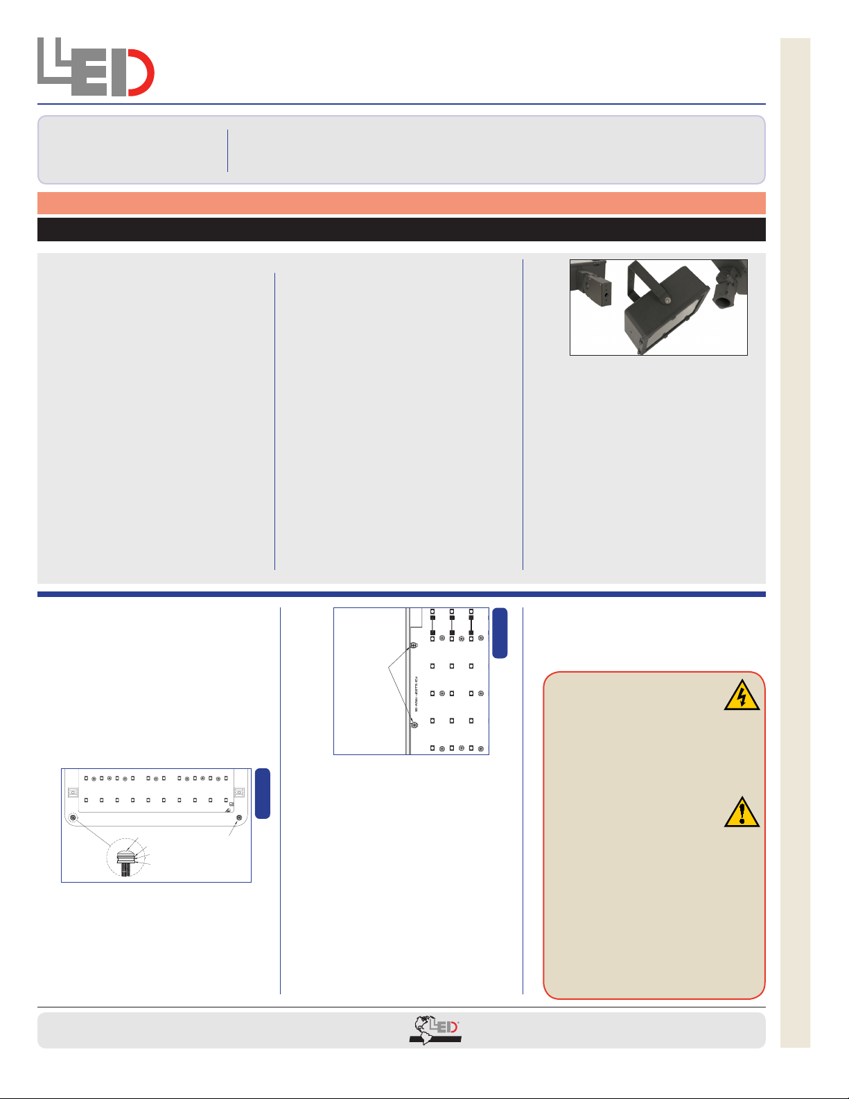
REMOVE PARTS1.
Remove 4 screws from the lens cover
to remove it from the back enclosure
(Figure 1).
Remove 4 screws to take out cluster
assembly from back enclosure (Figure 2).
KNOCK OUT / DRILL2.
Use provided knockouts for mounting
or drill holes into back enclosure as
necessary.
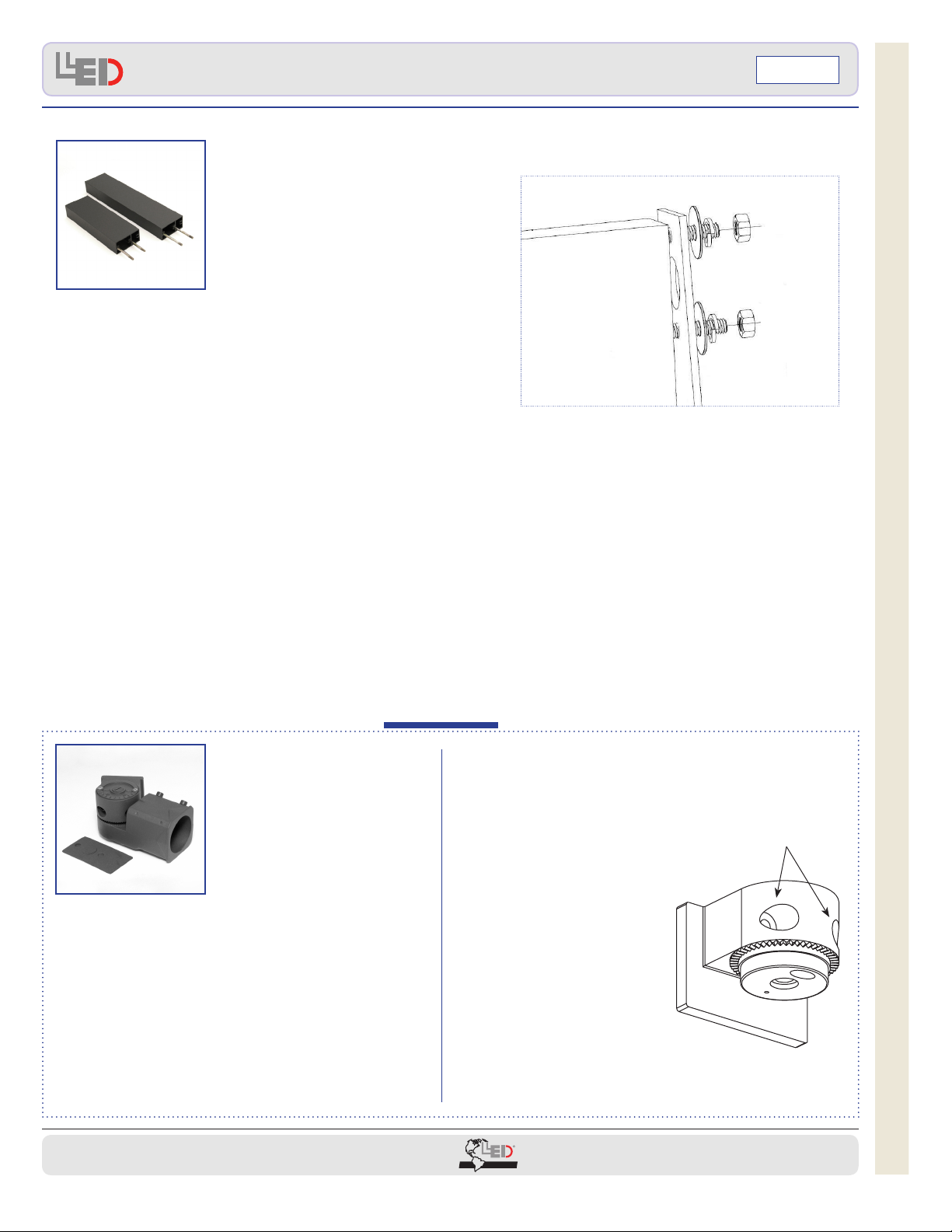
MOUNTING
Line up the back enclosure in the
desired location.
Mount securely with the customer-
provided screws.
REASSEMBLE LUMINAIRE3.
Use 4 screws to reinstall the cluster
assembly to the back enclosure (Figure
1).
Use 4 screws to attach the lens cover
to the back enclosure (Figure 2).
Flush Mount Installation
HAVE NEEDED ITEMS HANDY:1.
⊙Phillips screwdriver
⊙Slotted screwdriver
⊙Wrench
⊙Sealing material (wet
locations)
⊙Wire cutter/Strippers
⊙Twist-on wire connector (Wire
nuts)
BRACKET OR FLUSH MOUNT2.
To install the bracket, follow
the specic bracket installation
instructions on pp. 2-3, and
return to these instructions for
wiring.
To install by ush mount,
follow the specic installation
instructions below, and return to
these instructions for wiring.
3. WIRING
Ensure all power is OFF before
proceeding with wiring.
If needed, strip supply wires.
Use customer-provided
twist-on wire connectors (wire
nuts) for connection of supply
wires to luminaire wires. Connect
the black wire from xture to the
appropriate black supply wire
(hot). Connect the white wire
from xture to the white supply
wire (common). Attach the
ground supply wire to the green
ground wire.
Dress wires away from sharp
edges.
For wet locations, install to avoid4.
water entering or accumulating
in wiring compartments or other
electrical parts. Use sealing
material as needed.
Turn power on.5.
Figure 2
SCREW
WASHER
(4 PLCS)
On Both
Sides
CLUSTER
ASSEMBLY
Figure 1
WASHER
LENS COVER
#10-32 x 1”SCREW
1 SCREW
AT EACH
CORNER
O-RING
SEALING
WASHER