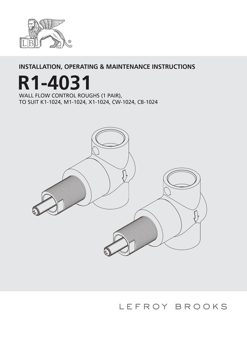
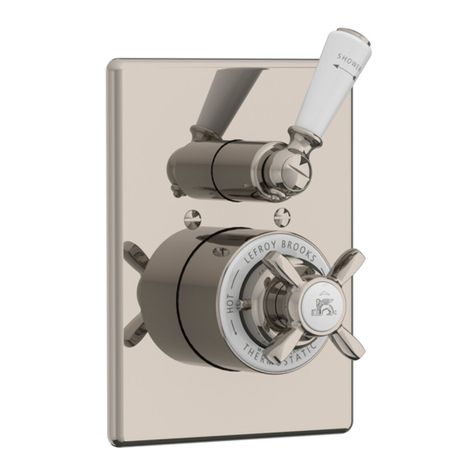
Lefroy Brooks M1-4010 Assembly instructions

INSTALLATION, OPERATING & MAINTENANCE INSTRUCTIONS
M1-4010 (MK 8700)
EXPOSED DUAL CONTROL THERMOSTATIC MIXING VALVE

2
Contents
Dimensions 3
InstalLation Procedure 4
Parts List 7
Fault Finder 8
Safety Tips, Care and Maintenance 9
Guarantee 10

8"
(203mm)
Ø 1 15/16"
(Ø49mm)
7 5/8"
(194.45mm)
3/4-14NPSM
5 3/4"
(146.55mm)
Ø 2 15/16"
(Ø74mm)
2 5/8"
(67mm)
1 7/16"
(37mm)
Ø 3 9/16"
(Ø90mm)
3
Dimensions in Inches (& Millimetres)
Whilst every effort is made to ensure accuracy, design and dimensions are subject to change without
notice as part of the company’s product development process.

4
3
5
1 2
6
Hot water
supply Cold water
supply
B
A
C
E
D
ø60
E
120˚
120˚
120˚
4
Steps 1-6
InstallationProcedure
Lefroy Brooks always recommends that plumbing products be installed by a licensed professional.
Shut off main water supply before installation.
1Before installing the valve, make sure the following three dimensions related to the nipples
protruding out of the wall surface are as shown.
A (distance between the centers of two nipples) : 8” (203mm)
B (diameter of the nipples) : 5/8” (15.98mm)
C (length of the nipples) : 3/6”~ 4/5” (15~20mm)
2Use a ruler to connect the centers of the two nipples and create a line D. Find the center
of this line and use dividers to create a circle E with a diameter of 2 9/25” (60mm).
3Divide the circle E into three parts equally, and mark them on the circle as shown.
4Drill holes where you have already marked, in the previous step, for the wall plugs.
5Fix the wall plugs into the wall.
6Attach the wall bracket to wall and fix it with screws.

10
9
8
7
5
InstallationProcedure Steps 7-10
Lefroy Brooks always recommends that plumbing products be installed by a licensed professional.
Shut off main water supply before installation.
7Attach the valve inlets onto the protruding nipples and place the body onto the wall bracket.
Fix the body to the wall bracket with set screws.
8Fix the nuts tightly to ensure sealing.
9Unscrew the set screw and take off the handle.
10 Undo the screw and take off the adaptor and stopper.

13
12
11
H
6
InstallationProcedure Steps 11-13
Lefroy Brooks always recommends that plumbing products be installed by a licensed professional.
Shut off main water supply before installation.
11 Turn on the flow controller. Turn the thermostatic cartridge untill you get the water temperature
at 38°.
Suggestion: attach a hose to outlet G and guide the water to a basin or other container while
you get the temperature right and to prevent any spillage on the floor.
12 Turn off the water supply. Install the stopper and make sure its “H” plane as the figure
mentioned is horizontal and on the left side.
13 Attach the adaptor and handle onto the valve.
When the adaptor is fixed, the temperature-limit-button (38°) is athorizontal position.

1 Handle (029685-51)
2 Set screw (292598)
3 Spring (005157)
4 Button (036292)
5 Pin (003168)
6 Canopy (018199-50)
7 O-ring (004623R)
8 Set screw (065086)
9 Canopy (071432-50)
10 Stopper (049108)
11 Retaining nut (104298)
12 Pin (003146)
13 Body (002679)
14 O-ring (004074N)
15 Adaptor (067568)
16 Check valve (519230)
17 Straine (058091)
18 Adapto (021008)
19 O-ring (004043)
20 Nut (009078)
21 Elbow (067567)
22 Compression olive (101161)
23 Nut (009328)
24 O-ring (004535N)
25 Escutcheon (019349)
26 Allen key (031000)
27 Allen key (031003)
28 Plastic anchor (291001)
29 Hex socket set screw (008003)
30 Escutcheon (071428)
31 Screw (008731)
32 Thermostatic cartridge (507132)
33 Cartridge (507455)
34 Canopy (018206)
35 Adaptor (067580)
36 End cap (109377)
37 Screw (008245)
38 Screw (065152)
39 Slotted head (008247)
40 Lever seat (205461)
41 Lever (108924)
42 Screw (017094)
43 Lever cap (109376)
1
2
13
32
11
33
10
9
34
35
40
39
42
41
43
36
30
29
6
4
3
15
16
18
21
5
19
8
25
23
17
22
7
27
37 24
14
28
31
26
12
20
38
7
PartsList Exploded view

8
FaultFinder
Fault Cause Rectification
Too low flow. Check valves or strainer clogged.
Showerheads clogged.
Water pressure from either hot or
cold is too low.
Remove and chean check valves
or strainer. May need to replace if
clogged.
Remove and clean showerheads.
May need to replace if clogged.
Check for water pressure and adjust
to proper pressure level.
Leaks around handle. Cartridge has come loose or
damaged.
Tighten/reinstall the cartridge or
replacement the cartridge if it is
damaged.

9
SafetyTips,CareandMaintenance
Safety Tips
If you are soldering during faucet installation,remove cartridges, seats, gaskets and washers prior to
applying flame, otherwise you will void the warranty.
Cover drain openings to avoid losing small parts.
When cutting or soldering pipe, use safety glasses to protect your eyes.
Important Points
Prior to beginning installation. turn off the cold and hot water lines and open the old faucet to release
built-up pressure.
Overtightening nuts may cause damage.
Wrap all threaded connections with pipe tape available at your local plumbing supply store.
Always wrap in a clockwise direction. The fittings should be installed by a state-licenced plumber.
Please note:
When there is a difference in water pressure between hot and cold supplies to the mixing valve, the
pressures should be equalized by a plumber in accordance with best practice and legislation.
Maintenance
Your new bathroom faucet is designed for years of trouble-free performance. Keep it looking new by
cleaning it periodically with a soft cloth. Avoid abrasive cleaners, wire wool and harsh chemicals as
these will dull the finish and void your warranty.
Routine Maintenance
The frequency and extent of attention required will vary according to prevailing site and operational
conditions, however a 12 monthly maintenance schedule is recommended.
If the product has operated satisfactorily for some time, but performance has been degraded, please
check the Fault Finder section to identify the problem.
Maintenance Check List
s 7ORNORDAMAGEDSEALSANDWASHERS
s $AMAGEDSEALFACES
s 4HREADWEAR
s )NCORRECTADJUSTMENT
s #OMPONENTFAILURE
s $EBRISORLIMESCALEBUILDUP

10
Guarantee
Guarantee of Quality
This product is guaranteed against faulty materials and workmanship for 12 months from date
of purchase. For the guarantee to be valid, the unit must be installed by a competent person, in
accordance with the instruction booklet.
Any part found to be defective during the guarantee period, will (at our option) be repaired or
replaced, free of charge, provided the unit has been installed, and properly used in
accordance with the instruction booklet.
Our products correspond to the valid technical and water supply standards as well as the relevant
approvals requirements. We guarantee them to be free of design and production faults at the time
of delivery and that with correct use and care in accordance with our printed instructions they will
function reliably.
Guarantee period
sThe guarantee is valid in private homes for 5 years from the purchase date. Proof of purchase
has to be provided when making a guarantee claim.
sBy use in commercial or institutional applications the guarantee is valid for 1 year after first use.
To make a guarantee claim, proof of purchase or, the beginning of use is required.
Not Covered by this Guarantee
Damage or defects arising from incorrect installation, improper use or lack of maintenance.
Installed product damaged in transit Consequential loss, damage or product removal and installation
costs.
Lefroy Brooks is not responsible for any on site labour charges.

The use of trademarks, product design and artwork is subject to licence or agreement with Christo A. Lefroy Brooks. The design
registrations, trademark registrations and copyrights are protected by law and the use or reproduction outside the terms of an agreement is prohibited.
The right to modify designs and dimensions is reserved. Christo Lefroy Brooks is a member of ACID (Anti Copying in Design).
LEFROY BROOKS INC, 1828 TROUTMAN STREET, RIDGEWOOD, NY, 11385
TELEPHONE: 718-302-5292. FAX: 718-302-4177
COPYRIGHT©LBIP LTD 2013
718-302-5292
www.lefroybrooks.com
This manual suits for next models
1
Table of contents
Other Lefroy Brooks Control Unit manuals
Popular Control Unit manuals by other brands

Emerson
Emerson ENARDO 860 Series instruction manual

Rockwell Automation
Rockwell Automation Trusted CS300 manual

Afag
Afag LM 12/30 Assembly and operating instructions

System Sensor
System Sensor MDL3W Installation and maintenance instructions

Hyperdyne Labs
Hyperdyne Labs HyperBlade SaberSD manual

taskit
taskit Panel-Card Technical reference

Lenze
Lenze ECSDS Series Mounting instructions

ICP DAS USA
ICP DAS USA M-7041 quick start guide

Fleck
Fleck 9000 Service manual

Tormatic
Tormatic T 100 DES Mounting and operating instructions

YOKOGAWA
YOKOGAWA WE7231 user manual

Flowserve
Flowserve Valtek CavControl Trim Installation, operation & maintenance instructions