manuals.online logo
Brands
  1. Home
  2. •
  3. Brands
  4. •
  5. Legacy
  6. •
  7. Subwoofer
  8. •
  9. Legacy Thumper User manual

Legacy Thumper User manual

Other Legacy Subwoofer manuals

Legacy LW1249 User manual

Legacy

Legacy LW1249 User manual

Legacy LW1057D User manual

Legacy

Legacy LW1057D User manual

Legacy Metro XD User manual

Legacy

Legacy Metro XD User manual

Legacy VS 12.2 User manual

Legacy

Legacy VS 12.2 User manual

Legacy Xtreme HD User manual

Legacy

Legacy Xtreme HD User manual

Legacy Goliath XD User manual

Legacy

Legacy Goliath XD User manual

Legacy Point One User manual

Legacy

Legacy Point One User manual

Legacy Pro 12 User manual

Legacy

Legacy Pro 12 User manual

Legacy LW12590 User manual

Legacy

Legacy LW12590 User manual

Legacy Metro User manual

Legacy

Legacy Metro User manual

Legacy LBF107 User manual

Legacy

Legacy LBF107 User manual

Popular Subwoofer manuals by other brands

Extron electronics SF 8CT SUB user guide

Extron electronics

Extron electronics SF 8CT SUB user guide

SVS PB-4000 quick start guide

SVS

SVS PB-4000 quick start guide

Pioneer S-DVR9SW Service manual

Pioneer

Pioneer S-DVR9SW Service manual

Yamaha YST-SW515 Service manual

Yamaha

Yamaha YST-SW515 Service manual

Velodyne SPL-800 ULTRA - REV B datasheet

Velodyne

Velodyne SPL-800 ULTRA - REV B datasheet

Teufel US 2110/1 SW operating instructions

Teufel

Teufel US 2110/1 SW operating instructions

Wet Sounds SS-65 user manual

Wet Sounds

Wet Sounds SS-65 user manual

Pyle PLQB10 Specifications

Pyle

Pyle PLQB10 Specifications

Sony XS-L1536 Product guide

Sony

Sony XS-L1536 Product guide

Sony XS-AW8 operating instructions

Sony

Sony XS-AW8 operating instructions

B&C Speakers 15 HPL 76W Specifications

B&C Speakers

B&C Speakers 15 HPL 76W Specifications

Velodyne DD-18+ Specifications

Velodyne

Velodyne DD-18+ Specifications

Sonance Cinema Series SUB 10-150 Specifications

Sonance

Sonance Cinema Series SUB 10-150 Specifications

Hifonics HW-12 Owners & installation manual

Hifonics

Hifonics HW-12 Owners & installation manual

Yamaha 64263 owner's manual

Yamaha

Yamaha 64263 owner's manual

Magnat Audio ADR 130 BP user manual

Magnat Audio

Magnat Audio ADR 130 BP user manual

Technics SB-AS500 Operaing instructions

Technics

Technics SB-AS500 Operaing instructions

Lyngdorf BW-2 owner's manual

Lyngdorf

Lyngdorf BW-2 owner's manual

manuals.online logo
manuals.online logoBrands
  • About & Mission
  • Contact us
  • Privacy Policy
  • Terms and Conditions

Copyright 2025 Manuals.Online. All Rights Reserved.

2
Registration
3. Owners Record
4. The Cabinetry / Our Commitment
Setup
5. Unpacking Your Speakers
6. Speaker Placement / Installation
8. Hook up Cables
10. Speaker Connections
Technology
13. Designer’s Note
15. Specifications
3
The model and serial numbers are located on the rear of the unit. Record
these numbers in the spaces provided below. Refer to them when calling
upon your dealer regarding this product.
Model No. _______________________________
Serial No. _______________________________
Date of purchase: _________________________
Thank you for selecting a Legacy Loudspeaker System. These hand-
crafted instruments will provide you with many years of listening
enjoyment. Please take a few moments to read this brief manual to insure
maximum benefit from your speaker system.
4
Handcrafted
Beneath the surface of Marquis’s elegant exterior lies rigid MDF
construction. Interlocking joinery maximizes the strength of the cabinet
parts. Polyester fiberfill is selected for internal damping. A sharp rap on
the enclosure will leave you with little more than bruised knuckles.
Each cabinet is impeccably finished on all exposed surfaces with select
veneers. The exquisite finish is hand-rubbed several times to assure a
patina at home with the most elegant decor.
Our Commitment
A great deal of forethought, love and satisfaction is instilled in each piece
of Legacy workmanship. We take pride in getting to know many of our
customers on a first name basis.
Your purchase of this product is backed by the renowned “Legacy
Satisfaction Guarantee”.
5
Your new subwoofer has been very carefully packaged to insure that it
travels to you safely. Each subwoofer is protected by a double-wall outer
carton with heavy V-board corner protectors. Molded foam end caps are
used to protect the elegant cabinetry, and a plastic liner is provided as
waterproofing. Please save this packing for future transportation. If cartons
become damaged or misplaced, new ones can be purchased from Legacy
Audio.
6
Since the human ear is rather poor at localizing radiation frequencies below 125
Hz, good results may be obtained in a variety of room placements. Careful
adjustment of the convenient front panel controls will lead to seamless transition.
Low frequency reinforcement occurs whenever woofers are placed near room
boundaries. The distance from the walls, floor and ceiling correspond to the
wavelengths of the frequencies, which will reflect in phase and thus reinforce bass
output. Therefore, the actual dimensions of your listening room play a definite
role in what ultimately arrives at your ear. In fact, rooms tend to have their own
set of favored frequencies.
We can calculate what the most strongly reinforced frequencies in a room will be
by the formula shown below:
Resonant Frequency = (1130 ft/sec) / (ft. between boundaries x 2)
For example, a room with an 8 ft. ceiling height has a strong resonance at: (1130
ft/sec.) / (8 ft. x 2) = 71 Hz.
7
Now, while such reinforcement might actually be beneficial at very low
frequencies, excessive excitation can cause “overhang” or a droning effect at mid-
bass frequencies. A way to minimize excitation of these resonances is to place
your subwoofer asymmetrically relative to room boundaries. For instance, if the
subwoofer is 2 ft from one corner wall, then place it 1.5 ft to 3 ft from the other.
Placing the subwoofer in a corner will reduce the radiation angle and thus
increase efficiency. It will also excite the maximum number of room modes and
decrease distortion.
A best case scenario is to actually use two subwoofers, one to each side of the
listener. The subs should be placed 90° out of phase with each other. This
improves spaciousness and bass uniformity, with a reduction in room level peaks.
8
The ideal conductor would have negligible resistance, inductance and
capacitance. The table below shows how a few actual speaker cables
measure up.
Cable Ωs/ft pF/ft µH/ft
12 ga. 0.0033 24 0.21
14 ga. 0.0048 17 0.13
16 ga. 0.0079 16 0.18
18 ga. 0.0128 28 0.21
Capacitance is considered insignificant in each cable because its effect is
well out of the audio bandwidth; inductance can be decreased (at the
expense of increased capacitance) by keeping the conductor pair closely
spaced.
How long would a cable have to be before inductance effects would
impinge on the audio spectrum? Approximately 300 feet of 12 gauge
would be required to establish a corner frequency of 20 kHz with an 8
Ohm loudspeaker. As you see, inductance is not a problem for most of us.
9
What about phase shift due to frequency dependent travel times down the
speaker cable? Measurements show that 100 Hz waves will be delayed
about 20 billionths of a second behind 10 kHz waves when traveling to the
end of a 10 foot speaker cable. Since the cilia of the ear requires 25,000
times longer than this just to transmit phase information, phase shifting is
obviously not the primary concern when considering speaker cables.
What about resistance? Finally we are getting somewhere.
Resistance is the controlling factor of the amplifier/loudspeaker interface.
Excessive resistance can cause major shifts of speaker crossover
frequencies. The lower the impedance of the loudspeaker, the greater the
effects of series resistance. A 20 foot run of 18 gauge cable can cause up
to 10% deviations of crossover center frequencies. That same 20 feet can
un-damp your damping factor and reduce your systems’ output by one-
half decibel.
In summary, there are no perfect cables. The best way to approximate the
ideal would be to keep loudspeaker leads as short as is practical.
10
Once you’ve found a place in your room, the next step is to connect
Thumper to your system. There are a variety of ways this can be
accomplished, all of which will be listed and explained.
Option 1: Connecting the Thumper using the Low Level Inputs (from
preamp/processor).
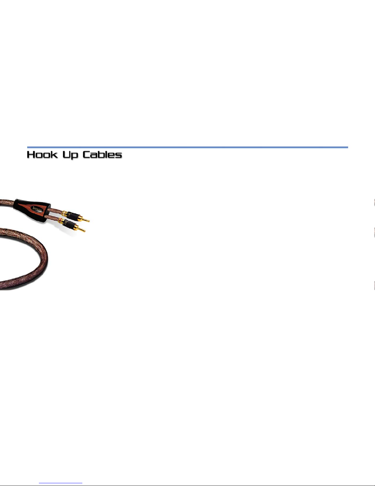
NOTE: if using the low-level inputs, we suggest using the shortest run of
shielded cables possible. Longer lengths of RCA cable can result in
greater noise and attenuation of the signal. If using Left/Right output jacks
from the preamp, the internal circuit module of the Thumper will sum the
two channels together. When using the left and right low level inputs on
the subwoofer, the internal crossover of the subwoofer is being used.
The crossover frequency and level will be controlled by the appropriately
labeled controls on the back panel of the sub. Connect the
preamp/processor’s “sub out” to the left channel RCA input (beneath
where it’s labeled “from preamp/processor.”) If your receiver/processor
has two subwoofer output jacks, you can connect either one or both of
these to the corresponding input jacks on the subwoofer.