Legend Flame EF290A User manual

23” Electric Fireplace Log Set
Model Number: EF290A
OWNER’S MANUAL
WARNING
Read and understand this entire owner’s manual, including all safety
information, before plugging in or using this product. Failure to do so
could result in fire, electric shock, or serious personal injury.
CAUTION
Keep this owner’s manual for future reference. If you sell or give this
product away, make sure this manual accompanies this product.
DO NOT RETURN!
Contact our customer service team for help first.
Call 949 385 6588
E-Mail: service5@fireandfireplaceservice.com

CONTENT
1. Important Safety Information …………………………………..………...........
1
2. Technical Specifications ………………………….…………………………………...
3
3. Before Installation …...........………………………….…………......................
4
4. Installation Instruction ....................................................................
5
5. Operation Instruction ……………………………………................................
7
5a. Manual Control Panel ……………..………………………….……...............
8
5b. Remote Control ……………………………….........................................
10
6. Care and Maintenance …………………….……….....................................
12
7. Limited Warranty …………………...……………………................................
13
8. Troubleshooting Guide ..……………………………………………………...........
14
9. Schematic Diagram …………………………………......................................
16

1
1. IMPORTANT SAFETY INFORMATION
WARNING
Read all instructions before using this appliance.
This heater is hot when in use. To avoid burns, DO NOT let bare skin
touch hot surfaces. If provided, use handles when moving this heater.
Keep combustible materials, such as furniture, pillows, bedding, papers,
clothes and curtains at least 3 feet (0.9m) from the front of the heater
and keep them away from the sides and rear.
Extreme caution is necessary when any heater is used by or near
children or invalids and whenever the heater is left operating and
unattended.
Always unplug heater when not in use.
DO NOT operate any heater with a damaged cord or plug or after the
heater malfunctions, has been dropped or damaged in any manner.
Discard heater, or return to authorized service facility for examination
and/or repair.
DO NOT use outdoors.
This heater is not intended for use in bathrooms, laundry areas and
similar indoor locations. Never locate heater where it may fall into a
bathtub or other water container.
DO NOT run power cord under carpeting. DO NOT cover power cord
with throw rugs, runners, or similar coverings. DO NOT route power
cord under furniture or appliances. Arrange power cord away from
traffic area, and where it will not be tripped over.
To disconnect heater, turn controls to off, then remove plug from
outlet.
Connect to properly grounded outlets only. (This item may be omitted
if the heater is not provided with a grounding type attachment plug.)

2
DO NOT insert or allow foreign objects to enter any ventilation or
exhaust opening, as this may cause electric shock or fire, or damage
the heater.
To prevent a possible fire, DO NOT block air intakes or exhaust in any
manner. Doing so could cause a fire. DO NOT use on soft surfaces, like
a bed, where openings may become blocked.
A heater has hot and arcing or sparking parts inside. DO NOT use it in
areas where gasoline, paint, or flammable liquids are used or stored.
Use this heater ONLY as described in this manual. Any other use not
recommended by the manufacturer may cause fire, electrical shock, or
injury to persons.
ALWAYS plug heaters directly into a wall outlet/receptacle. Never use
with an extension cord or relocatable power tap (outlet/power strip).
SAVE THESE INSTRUCTIONS.

3
2. TECHNICAL SPECIFICATIONS
Electric Specifications
Model Volt
Watt (min/max)
Hz
BTU(max)
Amp
Heating Area(max)
EF290A 120
750/1500 60
4600 12.5
400 square feet
Product Dimensions
22 7/8"
19 1/8" or 19 7/8"
21"
9 7/16"
13"
Power Cord 6ft

4
3. BEFORE INSTALLATION
Note:
Keep the packaging (carton, poly bag, polystyrene, etc.) for future
transportation and/or storage.
If the unit needs to be returned, please make sure all the spare parts
are packed inside, door handles are taken off, and packed the same
as the original packing.
Check Spare Parts
Open the packaging carefully and remove the polystyrene.
Check the spare part list below to verify all parts have been received.
Carefully check if any damages that may have for the insert or spare
parts.
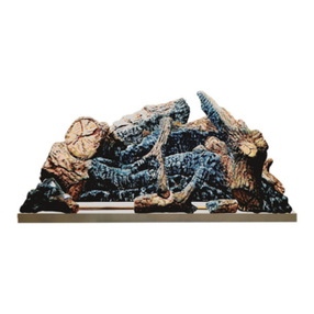
Log Insert (1 pc) Flame Screen (1 pc)
23” Electric Fireplace Log Set
Model Number: EF290A
OWNER'S MANUAL
WARNING
!Read and understand this entire owner's manual, including all safety
information, before plugging in or using this product. Failure to do so
could result in fire, electric shock, or serious personal injury.
CAUTION
Keep this owner's manual for future reference. If you sell or give this
product away, make sure this manual accompanies this product.
!
DO NOT RETURN!
Contact our customer service team for help first.
Call 949 385 6588
E-Mail: service5@fireandfireplaceservice.com
M5x12 Screws
(2 pcs)
Remote Handset
(1 pc)
Owner’s Manual
(1 pc)

5
Function Testing
Please refer to section 5a. Manual Control Panel and 5b. Remote Control
to test the appliance first before installation. Should any defects found,
please contact service team for help. Call 949 385 6588 or Email
service5@fireandfireplaceservice.com
4.
INSTALLATION INSTRUCTIONS
Locating the Appliance
Your new electric fireplace may be installed virtually anywhere in your
home. However, when choosing a location, ensure that the general
instructions for safety are followed.
For best results, install out of direct sunlight, water or very damp air.
Power supply service must be installed within proximity of electric
fireplace prior to finishing avoiding reconstruction.
Note: This model can NOT be hard wired.
Minimum Clearance to Combustibles
Sides............................0 inch
Floor............................0 inch
Back.............................0 inch
Top (shelf or TV)..........0 inch
Front............................36 inch
WARNING! Risk of Fire! Keep electrical cords, drapery, furnishings or
other combustibles at least 3ft. (0.9 m) from the front of the electric
fireplace.
Electrical Supply Circuit Requirements
Plan the location of the appliance so that it will have adequate electric
power. A 15 AMP, 60Hz circuit is required for 120V installation. The
appliance should ideally be located close to a suitable main socket to
enable power connection.

6
The power cord is 6ft long and locates on the right side of the unit. If
the cord is found not long enough to reach the outlet, a grounded
extension could be run from an existing socket outlet but a minimum
size 14 AWG with a minimum rating 1875W would be recommended,
and it should not be longer than 7ft and 10 31/64”.
Always make sure the outlet is in good condition and the plug is not
loose. NEVER exceed the maximum amperage of the circuit.
Installation
NOTE:
Do not lift by gripping the logs or the grate front legs. Lift it by holding
the sides of the heater box for stability.
Make sure there is clearance for air circulation beneath the unit.
If installing in an existing fireplace opening, seal all drafts and vents with
a non-fibrous insulation material to prevent any chimney debris from
falling onto the unit. Do not install into an existing fireplace opening that
is prone to dampness.
1. Fix the screen
Use 2pcs M5x12 Screws to fix the flame screen to the back of the firebox.
Note: There are 2 sets holes on the flame screen, if the opening is not
high enough, you can fix the screen through the top holes to lower the
total height of the log set to 19 1/8”.

7
2. Plug in
Make sure the plug is plugged very tightly and NO other appliances
should be plugged onto the same circuit.
3. Insert into the Opening
This unit does not require any special venting. It is recommended to install
it in an opening with the following Minimum dimensions for Best flame
effect to see:
A. 23 23/26" (605mm) wide
B. 22 1/8" (561mm) high
C. 11 7/16" (291mm) deep
5. OPERATING INSTRUCTIONS
WARNING! Do not operate the unit if it is damaged or has
malfunctioned. If you suspect the unit is damaged, call a
qualified service technician to inspect and replace any part of
the electrical system if necessary.
Read and understand this entire owner’s manual, including all
safety information, before plugging in or using this product.
Failure to do so could result in electric shock, fire, serious
injury, or death.
A
B
C

8
5a. Manual Control Panel
Flame(3 settings)
NO/OFF
Heater (750/1500w)
Thermostat
Note: When the heater is first turned on, a slight odor may be present.
This is normal and should not occur again unless the heater is not used
for a long period of time.
Heating Indicator Light Heating Indicator Light &
Remote Receiver

9
BUTTON NAME FUNCTION
POWER
SWITCH
Turn the main power switch on. A long
“beep” sound will be heard when the
switch is turned at ON Position “I”.
Note: The remote control will lost the
memory for function settings when the
switch is turned at OFF Position “O”.
FLAME
The flame will be cycled from Flame A –
Flame B – Flame C – Flame Off.
Flame A: full bright flame + little blue
Flame B: full bright flame
Flame C: half bright flame
HEATER
The heater will be cycled from Low – High
– Heater Off. The indicator light on the
bottom of the firebox (see the picture on
last page) will illuminate when the heater
is turned on. The indicator light will go out
within 10s.
Low: (●○)
High: (●●)
Note:
1. Heater can be used without flame.
2. The heater will work when the
temperature set by thermostat is
higher than room temperature.
3. The fan works about 10s ahead of the
heater, and stops about 10s later than
the heater.
4. The indicator light in the lower fuel
bed (see the picture on last page)
always illuminates when heater is on.

10
5
4
3
2
1
9
6
7
8
THERMOSTAT
Turn it to setting 9 first and when the
room has reached a desired level, turn
the rotary switch counterclockwise
slowly until the thermostat just ‘clicks’
off. The thermostat will then maintain
the room at this selected level. To
increase the temperature, turn the rotary
switch clockwise to a higher setting.
5b. Remote Control
Note
: Remote control can be used only when the main power switch is
on. Aim the remote control at the remote receiver
NOTE: A coin cell (CR2032) should be used for this remote but it is NOT included in
the package in consideration of the transportation safety, please source it locally.

11
BUTTON
TITLE FUNCTION
POWER
The power button will put the unit in standby
mode. This will turn off all functions and hold
the settings in memory, press the power
button again will turn on the unit to previous
settings.
For the first time use, Flame A will be turned
on.
FLAME The flame will be cycled from Flame A – Flame
B – Flame C – Flame Off.
LOW HEAT
To turn on the heater on half heat setting or
turn off the heater.
HIGH HEAT
To turn on the heater on full heat setting or
turn off the heater.
CRACKLING
To turn on the crackling and cycle through high
crackling sound - normal crackling sound - low
cracking sound - high crackling with wind sound
- normal crackling with wind sound - low
crackling with wind sound - off.
Temperature Limiting Control
This heater is equipped with a Temperature Limiting Control. Should the
heater reach an unsafe temperature, the heater will automatically turn
OFF. To reset:

12
Unplug the power cord from the outlet.
Turn the Power Switch on the CONTROL PANEL to OFF. Wait at least
5 minutes.
Inspect the fireplace to make sure no vents are blocked, or clogged
with dust or lint. If they are, use a vacuum to clean the vent areas.
With the Power Switch in the OFF position, plug the power cord back
into the outlet.
If it switches off again, UNPLUG THE HEATER RIGHT AWAY! Have the
outlets, wiring, and breaker box inspected by a professional. Make
necessary repairs before using the heater.
6. CARE AND MAINTENANCE
Cleaning
NEVER immerse in water or spray with water. Doing so could result in
electric shock, fire, or personal injury.
Metal:
Buff using a soft cloth, slightly dampened with a citrus oil-based product.
DO NOT use brass polish or household cleaners as these products will damage the
metal trim.
NEVER use abrasive cleansers, liquid sprays, or any cleaner that could scratch the
surface.
Vents:
Use a vacuum or duster to remove dust and dirt from the heater and vent areas.
Logs and base:
The log set should not be operated with an accumulation of dust or dirt on or in
the unit, as this can cause a build up of heat and eventual damage.
Dust and vacuum the log set as needed. Use a damp cloth and a mild detergent to
clean painted surfaces of the fireplace. Never use abrasive cleaners.
ALWAYS turn the heater OFF and unplug the power cord from the
outlet before cleaning, performing maintenance, or moving this
fireplace. Fail to do so could result in electric shock, fire, or personal
injury.

13
Flame screen:
The flame screen is cleaned in the factory during the assembly operation. During
shipment, installation, handling, etc., the screen may collect dust particles; these
can be removed by dusting lightly with a clean dry cloth.
To remove fingerprints or other marks clean the flame screen with a damp cloth.
Never use abrasive cleaners. Dry the screen completely with a lint free cloth to
prevent water spots.
Maintenance
Risk of electric shock! DO NOT OPEN! No user-serviceable parts
inside!
ALWAYS turn the heater OFF and unplug the power cord from the
outlet before cleaning, performing maintenance, or moving this
fireplace. Failure to do so could result in electric shock, fire, or
personal injury.
Electrical and Moving Parts:
The fan motors are lubricated at the factory and will not require lubrication.
Electrical components are integrated in the fireplace and are not serviceable by the
consumer.
Storage:
Store heater in a clean dry place when not in use.
Replacement parts:
Use only replacement parts supplied by the manufacturer. Use of any other parts,
or modifying the fireplace in any way, will void all warranties.
No internal parts are replaceable or serviceable.
7. LIMITED WARRANTY
This warrants to the original purchaser that this product is free from defects in
material and workmanship as of the date of purchase and that it will, under normal
use and proper care, remain so for one year from the date of purchase. Missing or
initially defective parts will be replaced free of charge during the period of this
limited warranty. If parts are unavailable, comparable replacement of refund will be
given. The original dated sales receipt is required for all warranty claims. This
warranty does not cover damage which has occurred during transport from the
point of purchase to the consumer’s home. This warranty does not cover glass, light
bulbs, batteries, transportation, labor, or other issues not associated with the
manufacture of the product.

14
This product is for residential use only. Any and all commercial use of this product
voids all warranties, and frees the manufacturer from all liability.
Read and understand all assembly and operating instructions, and all safety
information and warnings, before use. The following will void this warranty: Damage
caused from tampering with, modifying, or altering the fireplace insert in any
manner; Damage due to incorrect assembly, improper care, misuse, or abuse;
Damage from being used with the wrong power source; Water damage; Damage
caused from this insert being used outdoors; Damage caused from this insert being
used for excessive periods of time; Damage caused by the insert being used in a
commercial application; Damage from use as a primary heat source; Other misuse or
abuse not specifically listed herein.
This product is not intended to be used as a primary heat source. It is for
supplemental heating purposes only.
8. TROUBLESHOOTING GUIDE
1. The remote does not work and the new unit we just got cannot be turned on.
1) Make sure the main power switch on the top right behind the fence is on.
2) There would be a long beep when the main power switch is turned on.
3) If there is no beep, the connecters on the PCB board might be loosen,
please contact service team for a checking instruction.
4) If there is a beep and the control panel can be used but the remote is not
working, the remote is not working either close or far, please contact
service team for help.
2. My old unit no longer works, it cannot power on.
1) Check the power cord to see if it is well.
2) If the power cord is fine, check the wires behind the rocker switch to see if
they are burned.
3) If the wires are well, too, the PCB board might be broken and need to be
replaced. Please contact service team for a replacement and instruction.
3. The heater does not work, it turns on for several seconds then shuts off itself.
1) New product:
a. Turn the thermostat to 8 to see if the heater will work continuously.
b. If not, unplug the unit for a whole night.
c. If still not, contact service team for a checking instruction, the fan
assembly should be checked.
2) Product has been used for some time:
a. Open the top panel to check if the fan can move smoothly or the heater
motor is well connected.
b. If yes, pull off the CN3 connecter plugged on the PCB board. If the

15
heater works, the button panel should be replaced.
c. If the heater still does not work after unplugging the CN3 connecter,
please contact service team for a further solution.
4. There is no air coming out when turn the heater on.
1) New product:
a. Confirm if the air outlet feels warm or there is something getting red
inside when the heater is turned on. If yes, the fan is stuck or the heat
motor is not in right position.
b. If not, check the heater connecters on PCB board. Unplug and replug all
connecters to see if the heater will work.
2) Product has been used for some time:
a. Confirm if the air outlet feels warm or there is something getting red
inside when the heater is turned on. If yes, the fan is stuck or the heat
motor is not in right position.
b. If not, please contact service team for help.
5. The heater does not come back even the room is already cold.
Turn the thermostat to 8 to see if the heater will work continuously, if yes, the
sensor is malfunction, if not, please contact service team for help.
6. The flame does not show up or flicker or a noise when turn it on.
Please contact service team for a checking instruction of the flame LED board
connecter, flame motor and spindle.

16
9. SCHEMATIC DIAGRAM
Button Panel
Receiver
Fuel Bed LED Board
Heat Element
Manual Switch
Flame Motor
Thermostat
Heater Motor
~
θ
~
Sensor
Flame LED Board
Log LED Board
PCB
RC01-049A01
Power Cord
AC120V/60Hz
Tip Over Switch
Speaker

17

3.EF.290.05.002 A0
Legend Flame Group LLC
Address: 92 Corporate Park, Ste. C655 Irvine, CA 92606, United States
Table of contents
Popular Fireplace Accessories manuals by other brands

Valor
Valor Horizon/H4 installation manual

Travis Industries
Travis Industries Fireplace Xtrordinair 96300770 quick start guide

Lennox
Lennox H6977 installation instructions

Whalen
Whalen Houghton MNFP48HTN23HLAA manual

Esschert Design
Esschert Design Fancy Flames FF227 quick start guide

barbas
barbas 110-70 PF2 Preparation manual

Harvia
Harvia WX017 manual

Dimplex
Dimplex DFP4743 install guide

HITZE
HITZE TRIBOX TRI54x54x53.G installation manual

Heatilator
Heatilator DF-SAL60-PT installation instructions

Twin-Star International
Twin-Star International 23WM137 Assembly instructions

Hearth and Home Technologies
Hearth and Home Technologies DV425 quick start guide