Leggett & Platt Designer Series User manual

[adjustable bases ]
adjustablebases.com
© 2012 Leggett & Platt Adjustable Bed Group, a division of Leggett & Platt, Incorporated
MADE IN THE USA
NATIONWIDE CUSTOMER SERVICE
toll free: (800) 888-3078
99301294 EDR11908 3/12
OWNERS MANUAL
[adjustable bases ]


Designer Series™99301294
26
Repairs to or replacement of an adjustable
base or its components under the terms of
this limited warranty will apply to the original
warranty period and will not serve to extend
such period.
The decision to repair or to replace defective
parts under this warranty shall be made, or
cause to be made, by L&P at its option and in
its sole discretion.
Repair or replacement shall be the sole remedy
of the purchaser. There shall be no liability
on the part of L&P for any special, indirect,
incidental, or consequential damages or for
any other damage, claim, or loss not expressly
covered by the terms of this warranty.
This limited warranty does not include
reimbursement for inconvenience, removal,
installation, setup time, loss of use, shipping,
or any other costs or expenses. Leggett &
Platt or its service technicians shall not be
responsible for moving furniture or any other
items not attached to the adjustable base in
order to perform service on the adjustable base.
It is the sole responsibility of the purchaser
to provide adequate space and accessibility
to the adjustable base. In the event that the
technician is unable to perform service due
to lack of accessibility, the service call will be
billed to the purchaser and the service will have
to be rescheduled.
L&P makes no other warranty whatsoever,
express or implied, and all implied warranties
of merchantability and fitness for a particular
purpose are disclaimed by L&P and excluded
from this agreement.
Some states do not allow the exclusion or
limitation of incidental or consequential
damages, so the above limitation or exclusion
may not apply to every purchaser.
This warranty gives the purchaser specific legal
rights, and the purchaser may also have other
rights, which may vary from state to state. This
warranty is valid in all 50 states, Puerto Rico,
and Canada.
1-5-LIFETIME WARRANTY
WARRANTY INFORMATION
PO Box 668
Lexington, NC 27293
800-888-3078
For customer service online, email:
Please do not contact retail dealer or any other service personnel.
Advisory...................................................................................................................... 4
Acoustics.................................................................................................................... 6
Fabric Cleaning Information.......................................................................................... 6
Installation ................................................................................................................. 7
MR2T8-TVZG Function .............................................................................................. 17
Receiver Unit Programming ........................................................................................ 18
MR2T8-TVZG Programming ........................................................................................ 19
Troubleshooting ......................................................................................................... 24
1-5-Lifetime Warranty ................................................................................................ 25
CONTENTS
If adjustable base does not operate or if parts are missing, call:
800-888-3078
Do not contact retail store or dealer.

Designer Series™99301294
4
IMPORTANT INFORMATION
READ THE FOLLOWING INFORMATION CAREFULLY BEFORE USING THIS PRODUCT
ELECTRICAL RATING
Electrical components are rated for 110/120
voltage, 60Hz, 3.9 amp.
ELECTRICAL GROUNDING
This product is equipped with a polarized or
grounded electrical power cord. The power cord
will only fit into a grounded, electrical surge
protection device (not included) or a grounded
electrical outlet.
WARRANTY WARNING
Do not open any control boxes, motors or
remote control devices (with the exception of
the remote control and power down box battery
compartments). The product warranty will be
void if these components are tampered with. Do
not attempt to alter component wiring or adjust
or modify the structure of the product in any
way or the warranty will be void. Any repair or
replacement of base parts must be performed
by authorized personnel.
LUBRICATION
This product is designed to be maintenance
free. The lift motors are permanently lubricated
and sealed—no additional lubrication is
required. Do not apply lubricant to lift motor
lead screws or any nylon nuts or the bed may
inadvertently creep downward from the elevated
position.
PRODUCT RATINGS
The base lift motors are not designed for
continuous use. Reliable operation and full
life expectancy will be realized as long as
the lift motor operation does not exceed five
(5) minutes over a thirty (30) minute period,
or approximately 16% duty cycle. Note:
massage equipped bases are not designed
for continuous, extended massage operation.
Massage systems are rated for a maximum
of 2 hours of use within any 6 hour period.
Any attempt to circumvent or exceed product
ratings will shorten the life expectancy of the
product and may void the warranty.
The recommended weight restrictions for
this adjustable base is 600 lb (272 kg), all
sizes. The base will structurally support the
recommended weight distributed evenly across
the head and foot sections. This product is not
designed to support or lift this amount in the
head or foot sections alone. Note: exceeding
the recommended weight restrictions could
damage the base and void the warranty.
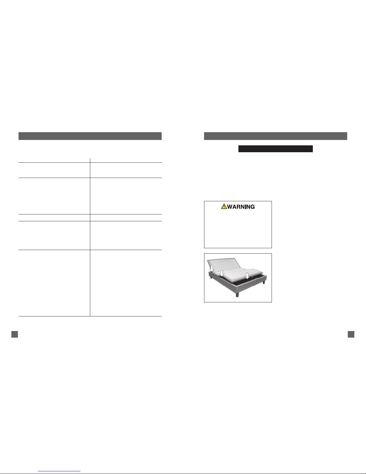
For best performance, consumers should enter
and exit the adjustable base with the base in
the flat (horizontal) position. DO NOT SIT ON
THE HEAD OR FOOT SECTIONS WHILE IN THE
RAISED POSITION.
UL (Underwriters Laboratories) recognized
components.
CFR 1633 approved for use with most
mattresses.
Made in USA.
ADVISORY
FOR OPTIMUM ADJUSTABLE BASE
OPERATION, USE A GROUNDED, ELECTRICAL
SURGE PROTECTION DEVICE (NOT
INCLUDED). FAILURE TO USE A SURGE
PROTECTION DEVICE COULD COMPROMISE
SAFETY OR CAUSE PRODUCT MALFUNCTION.
Designer Series™99301294 25
1-5-LIFETIME WARRANTY
Leggett & Platt, Incorporated (“L&P”) warrants this adjustable base to the consumer who is the
original purchaser (the “purchaser”), subject to the terms and conditions set forth herein. This
warranty begins on the “warranty commencement date” which is the date of purchase for new
unused bases and the date of manufacture for bases that have been used as floor or display models.
Thus, on a floor model base, the warranty is a portion of the limited lifetime warranty.
FULL 1 YEAR WARRANTY
This adjustable base is warranted against
defects in the workmanship or materials for
a period of one (1) year from the warranty
commencement date. Upon notice during the
first year after the warranty commencement
date, L&P will repair or replace (at no cost to
the purchaser) any defective adjustable base
part, and L&P will pay all authorized labor and
transportation costs associated with the repair or
replacement of any parts found to be defective.
5 YEAR LIMITED WARRANTY
During the second through the fifth year
from the warranty commencement date,
upon receipt of notice, L&P will replace any
adjustable base part found to be defective. This
limited five (5) year warranty shall not apply
unless the defective part is returned to L&P
within ten (10) days of purchaser’s receipt of
the replacement part. Purchaser shall pay all
service and transportation costs related to the
replacement of the defective part.
LIFETIME LIMITED WARRANTY
Upon notice during the sixth year through the
lifetime from the warranty commencement
date, L&P will replace, upon terms and
conditions set forth in this paragraph, any
mechanical base part found to be defective.
Electronics, electrical components, drive
motors and massage motors are excluded.
This limited lifetime warranty shall not
apply unless the defective part is returned
to L&P within ten (10) days of purchaser’s
receipt of the replacement part. In years 6 -
lifetime, purchaser shall pay all service and
transportation costs related to the replacement
of the defective part.
ADDITIONAL TERMS AND CONDITIONS
This warranty does not apply; (a) to any damage
caused by the purchaser; (b) if there has been
any repair or replacement of adjustable base
parts by an unauthorized person; (c) if the
adjustable base has been mishandled (whether
in transit or by other means), subjected to
physical or electrical abuse or misuse, or
otherwise operated in any manner inconsistent
with the operation and maintenance procedures
outlined in the Owners Manual and this
warranty; (d) to damage to mattresses, fabric,
cables, electrical cords or items supplied
by dealers. Contact the dealer for warranty
information on these items; (e) if there has
been any modification of the adjustable base
without prior written consent by L&P; (f) to
costs for unnecessary service calls, including
costs for in-home service calls solely for the
purpose of educating the consumer about the
adjustable base or finding an unsatisfactory
power connection; (g) if the recommended
weight restriction is not followed (refer to the
advisory section of this manual), the warranty
will be void.
Continued on next page...

Designer Series™99301294
24
TROUBLESHOOTING
In the event the adjustable base fails to operate, investigate the symptoms and possible
solutions provided in the chart below:
SYMPTOM SOLUTION
• Verify power cord is plugged into a working, grounded
electrical outlet. A grounded, electrical surge protection
device is recommended. Test outlet by plugging in
another working appliance.
• Program the remote control (see Remote Control
Programming section of this manual for programming
procedures).
• Unplug power cord, wait 30 seconds and plug in to
reset electronic components.
• Electrical circuit breaker may be tripped. Check
electrical service breaker box to verify.
• Defective surge protection device or electrical outlet.
Test outlet by plugging in another working appliance.
• Replace batteries in the remote control.
• Base mechanism may be obstructed. Elevate base and
check for obstruction. Remove obstruction.
• Head section may be too close to the wall.
• Headboard may be too close to the edge of the mattress.
Verify a 1.5” (38.1mm) to 2” (50.8mm) distance
between headboard brackets and mattress. Adjust if
required.
• Verify headboard brackets were removed during
installation. Remove headboard brackets if still
attached to the underneath side of base.
• If base is located on hard surface flooring, place carpet
pieces or rubber caster cups under each leg or caster
of the base. (See accessory section of this manual for
rubber caster cup order information.)
• Elevate the head or foot section a short distance (with
the remote control) to realign the lift/lower mechanisms
with the base support platform.
• Verify that the base is not positioned against a wall,
nightstand, or other object that may cause vibration or
noise.
• If base is installed over a base frame, verify massage
motors are not causing base frame (or base frame
components) to vibrate.
• Verify that headboard attachment hardware is tightened
firmly (if used).
Remote control illuminates and appears to be
operable, but will not activate base.
No features of the base will activate.
Remote control will not illuminate.
Head or foot section will elevate, but will not
return to the horizontal (flat) position.
Excessive massage motor noise.
Designer Series™99301294 5
ADVISORY
READ THE FOLLOWING INFORMATION CAREFULLY BEFORE USING THIS PRODUCT
PACEMAKER WARNING
This product produces a vibrating sensation.
It is possible that individuals with heart-assist
pacemakers may experience a sensation similar
to exercise. Consult physician for complete
information.
HOSPITAL USE DISCLAIMER
This base is designed for in-home use only. It
is not approved for hospital use and does not
comply with hospital standards. Do not use this
base with tent type oxygen therapy equipment,
or use near explosive gases.
SERVICE REQUIREMENTS
Service technicians are not responsible for
moving furniture, removing headboards and
footboards or any items required to perform
maintenance on the base. In the event the
technician is unable to perform service due
to lack of accessibility, the service call will
be billed to the purchaser and the service will
have to be rescheduled.
FCC COMPLIANCE
Components meet Class B digital device
rating (Part 15, FCC rules) for residential use.
Adjustable bases generate, use and may radiate
radio frequency energy. Radio communication
may be affected if not installed and operated
as recommended in this manual. Changes
or modifications not approved by the party
responsible for compliance could void the
user’s authority to operate the equipment.
Radio frequency = 310MHz.
IMPORTANT INFORMATION
SMALL CHILDREN / PETS WARNING
After the base is unboxed, immediately dispose
of packaging material as it can smother small
children and pets. To avoid injury, children or
pets should not be allowed to play under or on
the base. Children should not operate this base
without adult supervision.
FIGURE 1: Pinch point areas.
DURING BASE OPERATION, GAPS (PINCH
POINTS) ARE CREATED (FIGURE 1). A CHILD,
A PERSON’S LIMB, OR A PET CAN BECOME
ENTRAPPED AT THESE LOCATIONS. DURING
USE, AND WHEN BASE IS IN THE RAISED
POSITION, ALWAYS KEEP GAP AREAS (PINCH
POINTS) CLEAR AND KEEP ALL LIMBS ON
TOP OF BASE. FAILURE TO FOLLOW THIS
WARNING COULD RESULT IN SERIOUS
INJURY OR DEATH.
PINCH POINT WARNING

Designer Series™99301294
6
ACOUSTICS
LIFTING/LOWERING MECHANISMS
The lift/lower feature will emit a minimal
humming sound during operation. This is
normal.
During operation, the lift arm wheels make
contact with the platform support of the base.
This applies slight tension on the moving
components and resonance is reduced to a
minimum level. If excessive noise or vibration
is experienced, reverse the movement action
(up or down) of the base with the hand control.
This should realign the base’s activating
mechanisms to the proper operational position.
MASSAGE OPERATION
The massage feature will emit a minimal tone
during operation. This is normal. When the
massage level is increased, motor resonance
will intensify accordingly.
LOCATION ENVIRONMENT
The level of sound experienced during
operation is directly related to the location
environment. For example, when a base is
located on a hardwood floor with the massage
feature in operation, a vibrating tone will be
audible. To minimize this resonance, place a
piece of carpet, or rubber caster cups, under
each leg or caster of the base.
It is possible to experience vibration or noise
from the headboard brackets, headboards or
footboards if mounting bolts are not firmly
tightened.
FABRIC CLEANING INFORMATION
Spot clean only with water based shampoo
or foam upholstery cleaner. Pretest a small,
inconspicuous area before proceeding. Do
not over wet. Do not use solvents to spot
clean. Pile fabrics may require brushing with
a non-metallic, stiff bristle brush to restore
appearance. Hot water extraction or steam
cleaning is not a recommended cleaning
method.
To prevent overall soiling, frequent vacuuming
or light brushing with a non-metallic stiff
bristle brush to remove dust and grime is
recommended. When cleaning a spill, blot
immediately to remove spilled material. Clean
spots or stains from the outside to the middle
of the affected area to prevent circling. Use a
professional furniture cleaning service when an
overall soiled condition is apparent.
Designer Series™99301294 23
MR2T8-TVZG REMOTE CONTROL PROGRAMMING (separating 2 bases)
REMOTE CONTROL 1
BASE 1
BASE 2
REMOTE CONTROL 2
Program Two Remotes to Operate Two Bases - your
adjustable base will be equipped with one of the following:
(A) a DC motor with a power down box, (B) an AC J box,
(C) a DC motor without a power down box (FIGURE 13).
NOTE: operate only one (1) remote control at a time.
Operating two (2) remote controls at the same time
will momentarily block both rf signals and prevent both
controls from functioning.
STEP 3
Repeat Step 1 and Step 2 with remote control 1.
Note: Wait 90 seconds before proceeding to Step 4.
STEP 4 (BASE 2)
(A) DC motor with a power down box: press the learn
button on the power down box for 1 second.
(B or C) AC Jbox or DC motor without power down
box: unplug the adjustable base electrical power
cord. Wait 30 seconds, then plug the cord back into
the power source.
STEP 5
On remote control 2, simultaneously press and hold
the foot up and tv position buttons (FIGURE 14).
The transmission indicator light will flash slowly and
then flash rapidly to indicate programming mode.
Continue to hold for 5 seconds and then release the
buttons.
STEP 6
Repeat Step 4 and Step 5 with remote control 2.
Independent remote control operation is now
restored (remote control 1 operating base 1; remote
control 2 operating base 2).
FIGURE 13: Power down box, AC J box and DC motor.
LEARN
BUTTON
POWER
DOWN BOX
AC J BOX
POWER DOWN
BOX (NOT
MOUNTED TO
BASE FRAME)
AC J BOX
(MOUNTED
TO BOTTOM
SIDE OF BASE
FRAME)
LEARN
BUTTON
DC MOTOR-NO
POWER DOWN
BOX
DC MOTOR
(MOUNTED TO
BOTTOM SIDE OF
BASE FRAME)
A
B
C
STEP 1 (BASE 1)
(A) DC motor with a power down box: press the learn
button on the power down box for 1 second.
(B or C) AC Jbox or DC motor without power down
box: unplug the adjustable base electrical power
cord. Wait 30 seconds, then plug the cord back into
the power source.
STEP 2
On remote control 1, simultaneously press and hold
the foot up and tv position buttons (FIGURE 14).
The transmission indicator light will flash slowly and
then flash rapidly to indicate programming mode.
Continue to hold for 5 seconds and then release the
buttons.
FOOT UP
BUTTON
TV POSITION
BUTTON
TRANSMISSION
INDICATOR
LIGHT
FIGURE 14

Designer Series™99301294
22
MR2T8-TVZG REMOTE CONTROL PROGRAMMING (2 remote controls - 2 bases)
Program Two Remotes to Operate Two Bases - your
adjustable base will be equipped with one of the
following: (A) a DC motor with a power down box, (B)
an AC J box, (C) a DC motor without a power down
box (FIGURE 13). NOTE: operate only one (1) remote
control at a time. Operating two (2) remote controls at
the same time will momentarily block both rf signals
and prevent both controls from functioning. REMOTE
CONTROL 1
REMOTE
CONTROL 2
BASE 1
BASE 2
STEP 3
Repeat Step 1 and Step 2 with remote control 2.
STEP 4 (BASE 2)
(A) DC motor with a power down box: press the learn
button on the power down box for 1 second.
(B or C) AC Jbox or DC motor without power down
box: unplug the adjustable base electrical power
cord. Wait 30 seconds, then plug the cord back into
the power source.
STEP 5
On remote control 1, simultaneously press and hold
the foot up and tv position buttons (FIGURE 14).
The transmission indicator light will flash slowly and
then flash rapidly to indicate programming mode.
Continue to hold for 5 seconds and then release the
buttons.
STEP 6
Repeat Step 4 and Step 5 with remote control 2.
Two remote controls are now programmed to operate
two bases.
FIGURE 13: Power down box, AC J box and DC motor.
LEARN
BUTTON
POWER
DOWN BOX
AC J BOX
POWER DOWN
BOX (NOT
MOUNTED TO
BASE FRAME)
AC J BOX
(MOUNTED
TO BOTTOM
SIDE OF BASE
FRAME)
LEARN
BUTTON
DC MOTOR-NO
POWER DOWN
BOX
DC MOTOR
(MOUNTED TO
BOTTOM SIDE OF
BASE FRAME)
A
B
C
STEP 1 (BASE 1)
(A) DC motor with a power down box: press the learn
button on the power down box for 1 second.
(B or C) AC Jbox or DC motor without power down
box: unplug the adjustable base electrical power
cord. Wait 30 seconds, then plug the cord back into
the power source.
STEP 2
On remote control 1, simultaneously press and hold
the foot up and tv position buttons (FIGURE 14).
The transmission indicator light will flash slowly and
then flash rapidly to indicate programming mode.
Continue to hold for 5 seconds and then release the
buttons.
FOOT UP
BUTTON
TV POSITION
BUTTON
TRANSMISSION
INDICATOR
LIGHT
FIGURE 14
Designer Series™99301294 7
INSTALLATION
For installation and setup, complete the following procedures, in the order indicated below
and on the following pages:
MATTRESS
RETAINER
(1 per base)
STEP 1
Before discarding any packing materials,
check the adjustable base shipping carton
and verify the following items are
included:
• (1) Mattress Retainer
• (4) Bed Legs
• (2) Headboard Bracket Assemblies
• (1) Headboard Bracket Hardware Kit (blister card)
• (1) Remote Control
• (1) Owners Manual
• (1) Warranty Activation Card
• (1) Quick Setup Guide
LEG
(4 pieces)
REMOTE CONTROL
HEADBOARD BRACKET ASSEMBLIES - HARDWARE
(4 bracket pieces, hardware blister card)
(2) Bracket Weldments
(2) Flange Weldments
Blister Card
OWNERS MANUAL
WARRANTY
ACTIVATION CARD
QUICK SETUP GUIDE
5/16-18 Threads

Designer Series™99301294
8
INSTALLATION
STEP 2
Carefully lift the adjustable base out of the shipping
carton and position it on its side on a clean surface.
While holding it steady and secure, screw the legs
into the tapped inserts at each corner of the base
(FIGURE 2). NOTE: DO NOT LET BASE REST ON
LEGS!
FIGURE 2: Leg installation.
TAPPED INSERTS
FOR LEGS
LEGS INSTALLED
DO NOT ATTEMPT TO SCREW
LEGS INTO ANY OTHER INSERTS.
THIS WILL DAMAGE PRODUCT.
CAUTION
AT LEAST TWO PEOPLE ARE
RECOMMENDED FOR HANDLING AND
MOVING ADJUSTABLE BASE.
Designer Series™99301294 21
MR2T8-TVZG REMOTE CONTROL PROGRAMMING (1 remote control - 2 bases)
STEP 3
Repeat Step 1 and Step 2 with base 2.
One remote control is now programmed to
operate two bases.
FOOT UP
BUTTON
TV POSITION
BUTTON
TRANSMISSION
INDICATOR LIGHT
FIGURE 14
BASE 1
BASE 2
FIGURE 13: Power down box, AC J box and DC motor.
LEARN
BUTTON
POWER
DOWN BOX
AC J BOX
POWER DOWN
BOX (NOT
MOUNTED TO
BASE FRAME)
AC J BOX
(MOUNTED
TO BOTTOM
SIDE OF BASE
FRAME)
LEARN
BUTTON
DC MOTOR-NO
POWER DOWN
BOX
DC MOTOR
(MOUNTED TO
BOTTOM SIDE OF
BASE FRAME)
A
B
C
Program One Remote to Operate Two Bases - your adjustable
base will be equipped with one of the following: (A) a DC motor
with a power down box, (B) an AC J box, (C) a DC motor without
a power down box (FIGURE 13).
STEP 1
(A) DC motor with a power down box: press
the learn button on the power down box for 1
second.
(B or C) AC Jbox or DC motor without power
down box: unplug the adjustable base electrical
power cord. Wait 30 seconds, then plug the
cord back into the power source.
STEP 2
On the remote control, simultaneously press
and hold the foot up and tv position buttons
(FIGURE 14). The transmission indicator
light will flash slowly and then flash rapidly to
indicate programming mode. Continue to hold
for 5 seconds and then release the buttons.

Designer Series™99301294
20
MR2T8-TVZG REMOTE CONTROL PROGRAMMING
(
2 remote controls - 1 base)
OPERATE ONLY ONE (1) REMOTE CONTROL
AT A TIME. OPERATING TWO (2) REMOTE
CONTROLS AT THE SAME TIME WILL
MOMENTARILY BLOCK BOTH RF SIGNALS
AND PREVENT BOTH CONTROLS FROM
FUNCTIONING.
NOTE
STEP 3
Repeat Step 1 and Step 2 with remote control 2.
Two remote controls are now programmed to
operate one base.
FOOT UP
BUTTON
TV POSITION
BUTTON
TRANSMISSION
INDICATOR LIGHT
FIGURE 14
REMOTE
CONTROL 1
REMOTE
CONTROL 2
FIGURE 13: Power down box, AC J box and DC motor.
LEARN
BUTTON
POWER
DOWN BOX
AC J BOX
POWER DOWN
BOX (NOT
MOUNTED TO
BASE FRAME)
AC J BOX
(MOUNTED
TO BOTTOM
SIDE OF BASE
FRAME)
LEARN
BUTTON
DC MOTOR-NO
POWER DOWN
BOX
DC MOTOR
(MOUNTED TO
BOTTOM SIDE OF
BASE FRAME)
A
B
C
Program Two Remotes to Operate One Base - your
adjustable base will be equipped with one of the
following: (A) a DC motor with a power down box,
(B) an AC J box, (C) a DC motor without a power
down box (FIGURE 13).
STEP 1
(A) DC motor with a power down box: press
the learn button on the power down box for 1
second.
(B or C) AC Jbox or DC motor without power
down box: unplug the adjustable base electrical
power cord. Wait 30 seconds, then plug the
cord back into the power source.
STEP 2
On the remote control, simultaneously press
and hold the foot up and tv position buttons
(FIGURE 14). The transmission indicator
light will flash slowly and then flash rapidly to
indicate programming mode. Continue to hold
for 5 seconds and then release the buttons.
Designer Series™99301294 9
INSTALLATION
STEP 4
Carefully rotate the adjustable base over to
position the base top-side-up (FIGURE 3).
FIGURE 3: Adjustable base oriented top-side-up.
STEP 3
Keeping base steady and secure, extend out
power cord for easy access when base is
oriented top-side-up.
POWER CORDS MUST NOT INTERFERE WITH
ANY ADJUSTABLE BASE MECHANISMS.

Designer Series™99301294
10
STEP 5
Plug electrical power cord into a working, grounded electrical outlet.
Note: an electrical surge protection device is recommended (not included).
STEP 6
Install batteries in remote control. Briefly activate all functions of the base
with the remote control to verify all features are in working order. If base
does not operate, refer to the Troubleshooting section of this manual.
STEP 7
Return base to the level position.
STEP 8
Install mattress retainer at the foot end of the adjustable base as follows:
a. Locate grommeted holes at foot of base (FIGURE 4).
INSTALLATION
FIGURE 4: Grommeted hole locations.
GROMMETED
HOLES
FOOT END OF BASE
Designer Series™99301294 19
MR2T8-TVZG REMOTE CONTROL PROGRAMMING
(
1 remote control - 1 base)
Program One Remote to Operate One Base - your adjustable
base will be equipped with one of the following: (A) a DC motor
with a power down box, (B) an AC J box, (C) a DC motor without
a power down box (FIGURE 13).
STEP 1
(A) DC motor with a power down box: press
the learn button on the power down box for 1
second.
(B or C) AC Jbox or DC motor without power
down box: unplug the adjustable base electrical
power cord. Wait 30 seconds, then plug the
cord back into the power source.
STEP 2
On the remote control, simultaneously press
and hold the foot up and tv position buttons
(FIGURE 14). The transmission indicator
light will flash slowly and then flash rapidly to
indicate programming mode. Continue to hold
for 5 seconds and then release the buttons.
One remote control is now programmed to
operate one base.
FOOT UP
BUTTON
TV POSITION
BUTTON
TRANSMISSION
INDICATOR LIGHT
FIGURE 14
FIGURE 13: Power down box, AC J box and DC motor.
LEARN
BUTTON
POWER
DOWN BOX
AC J BOX
POWER DOWN
BOX (NOT
MOUNTED TO
BASE FRAME)
AC J BOX
(MOUNTED
TO BOTTOM
SIDE OF BASE
FRAME)
LEARN
BUTTON
DC MOTOR-NO
POWER DOWN
BOX
DC MOTOR
(MOUNTED TO
BOTTOM SIDE OF
BASE FRAME)
A
B
C

Designer Series™99301294
18
AC J BOX / DC MOTOR without power down box PROGRAMMING PROCEDURE
When programming the remote control, unplug
the adjustable base electrical power cord. Wait
30 seconds, then plug the cord back into the
power source. This process automatically sets
the bed to the program mode for 90 seconds.
For convenience, use this procedure in lieu of
pressing the learn button (located on the AC
J Box, mounted to the underside of the base
frame).
Note that this programming feature is only
applicable to bases without a power down box.
Power down equipped adjustable bases require
use of the learn button on the power down box
when programming the remote control.
In case of a power outage, press and hold the
learn button on the power down box to lower
the base to the flat position (FIGURE 12).
This function is only for lowering the base and
will not operate the base to any other position.
The two (2) 9 volt batteries should be replaced
after this function is used.
In the event the power down feature does not
work, check to make sure the two (2) 9 volt
batteries are good.
The power down box is factory wired to the motor,
but the box itself is mobile and can be placed
anywhere under the adjustable base on the floor.
Position the power down box near your remote
control when programming for best results.
POWER DOWN BOX OPERATION
POWER
DOWN BOX
LEARN
BUTTON
FIGURE 12: Power down box learn button.
For adjustable bases equipped with AC J box or DC motor only—no power down box.
POWER DOWN BOX BATTERY INSTALLATION
PRESS IN (SLIGHTLY) AND
PUSH DOW TO REMOVE
BATTERY COMPARTMENT
DOOR
BATTERY ORIENTATION IS
INDICATED INSIDE BATTERY
COMPARTMENT
DOOR INSTALLATION:
PRESS COMPARTMENT
DOOR AGAINST THE
BATTERY ENDS, SLIDE
DOOR UP AND IN TO
ENGAGE THE DOOR
TABS
TABS
STEP 1 STEP 2
Designer Series™99301294 11
NOTE: If base is to be set up without a headboard,
basic installation is now complete. If headboard is to be
installed, proceed to Headboard Bracket Installation.
b. Place mattress retainer ends into grommeted holes in top surface of
adjustable bed base (FIGURES 4 and 5). Press down until horizontal
retainer section is flush against bed base.
INSTALLATION
FIGURE 5: Mattress retainer installation.
MATTRESS
RETAINER
FOOT END OF BASE

Designer Series™99301294
12
3 inches MAX.
FIGURE 6: Headboard cross member location must not exceed 3 inches
(76.2mm) from the top of the mattress.
HEADBOARD BRACKET INSTALLATION
INSTALLATION
FAILURE TO FOLLOW HEADBOARD BRACKET
INSTALLATION INSTRUCTIONS MAY CAUSE
HEADBOARD BRACKET INTERFERENCE WITH
BASE FOAM DURING BED OPERATION. BASE
FOAM OR BASE COVER DAMAGE COULD
RESULT.
NOTE
IN ORDER TO AVOID A PERSON OR PET BEING CAUGHT
IN THE SPACE REFERENCED BELOW WHILE THE BASE IS
IN MOTION, THE BOTTOM OF THE HEADBOARD CROSS
MEMBER MUST BE POSITIONED SO THAT THERE IS
NO MORE THAN 3 INCHES (76.2mm) BETWEEN THE
HEADBOARD AND THE TOP OF THE MATTRESS (FIGURE
6). DO NOT EXCEED 3 INCHES (76.2mm). FAILURE TO
FOLLOW THIS INSTRUCTION COULD RESULT IN SERIOUS
PERSONAL INJURY OR DEATH.
Designer Series™99301294 17
MR2T8-TVZG FUNCTION
NOTE
REMOTE CONTROL REQUIRES FOUR (4) AAA SIZE BATTERIES. TO CONSERVE
BATTERY LIFE, THE TRANSMITTER TURNS OFF ALL FUNCTIONS WHEN ANY BUTTON
IS PRESSED FOR MORE THAN 50 SECONDS.
MEMORY BUTTON
Press to capture any position and/or
function of the base as a programmed
position. Press the custom button to
adjust the base to the programmed
position.
To Program Memory Position:
1. Adjust the base to any desired position
and/or massage/wave combination.
2. Press the memory button and then the
custom button to save selection.
TRANSMISSION INDICATOR LIGHT
Verifies a button is being pressed and
data is being sent to the base.
FOOT MASSAGE BUTTONS
To activate the foot massage, press
and release the increase button.
Adjust massage intensity by pressing
and holding the increase or decrease
button. To turn off, press and hold the
decrease button until the massage
turns off.
HEAD MASSAGE BUTTONS
To activate the head massage, press
and release the increase button.
Adjust massage intensity by pressing
and holding the increase or decrease
button. To turn off, press and hold the
decrease button until the massage
turns off.
HEAD UP/DOWN BUTTONS
Press and hold to raise or lower the
head section.
FOOT UP/DOWN BUTTONS
Press and hold to raise or lower
the foot section.
TV POSITION BUTTON
Press to adjust the base to the
preprogrammed tv viewing position to
maximize comfort and entertainment.
This position is reprogrammable using
the memory button. To reprogram,
adjust base to desired position, press
the memory button, then press the tv
position button. The position is now
saved.
ZERO GRAVITY BUTTON
Press to adjust the base to the
preprogrammed reclined position for
optimum weight distribution allowing
total comfort and relaxation. This
position is reprogrammable using the
memory button. To reprogram, adjust
base to desired position, press the
memory button, then press the zero
gravity button. The position is now
saved.
FLAT BUTTON
Press to adjust the base to the
level position.
CUSTOM BUTTON
Press to adjust the base to position
programmed using the memory button.
WAVE LOW BUTTON
Press and hold—after the wave has
been activated—to decrease wave
speed. To turn wave off, press and
hold until wave stops.
WAVE HIGH BUTTON
After the head and/or foot massager/s
have been activated and the desired
intensity has been achieved, press to
turn the wave on. Press and hold to
increase wave speed.

Designer Series™99301294
16
INSTALLATION
h. Measure the center-to-center distance between the mounting slots of the
headboard bracket flanges (FIGURE 11).
i. If bracket flange adjustment is required to accept the headboard, remove the
1 inch long hex head bolts and move flanges side-to-side for the adjustment
(FIGURE 11). Reinstall bolts. Tighten all headboard mounting bolts.
j. Firmly tighten all bolts of both headboard bracket assemblies.
k. Install headboard.
Typical Designer Series™ adjustable base installation is now complete.
STEP 10
Install mattress on adjustable base.
MEASURE FLANGE SLOTS
CENTER-TO-CENTER TO CHECK
HEADBOARD HOLE LOCATION
REMOVE 1 INCH LONG HEX HEAD BOLTS AND RELOCATE
FLANGES TO ACHIEVE CENTER-TO-CENTER DISTANCE
REQUIRED FOR HEADBOARD MOUNTING HOLES
FIGURE 11: Headboard bracket measurement and adjustment to accept headboard.
Designer Series™99301294 13
STEP 9 (Optional - if headboard is to be attached)
Install headboard brackets to the adjustable base frame as follows:
a. Using the remote control, raise the head section of the base as far as it
will articulate to gain access to the adjustable base frame.
b. Insert a 1/2” carriage bolt into a headboard bracket weldment
(FIGURE 7).
INSTALLATION
FIGURE 7: Headboard bracket weldment.
1/2” CARRIAGE
BOLT
HEADBOARD
BRACKET
WELDMENT

Designer Series™99301294
14
c. Locate (2) slotted holes in base frame at one corner of head
end of base. Place the headboard bracket weldment underneath
base frame and against the head end of the base, positioning
the bracket weldment so the carriage bolt appears through the
innermost slotted hole in the base frame (FIGURE 8). Place hex
nut on 1/2” long carriage bolt to attach bracket weldment to base
frame. Loosely tighten to allow adjustment for headboard hole
alignment. Place second 1/2” long carriage bolt in remaining slot
and secure using hex nut. Loosely tighten to allow adjustment for
headboard hole alignment.
INSTALLATION
FIGURE 8: Headboard bracket weldment installation.
HEADBOARD
BRACKET
WELDMENT
HEAD END
OF BASE
FRAME
SLOTS
1/2 INCH LONG
CARRIAGE BOLT
Designer Series™99301294 15
INSTALLATION
d. Place headboard flange weldment against headboard bracket
weldment. Install (2) 1” long hex bolts through slots in headboard
bracket weldment and holes in headboard flange weldment
(FIGURE 9). Secure using (2) hex nuts. Loosely tighten to allow
adjustment for headboard hole alignment.
e. Repeat procedure to attach the other headboard bracket assembly
(FIGURE 10).
FIGURE 10: Headboard bracket installed to one corner of adjustable base.
USE (2) 1 INCH LONG HEX HEAD
BOLTS TO ATTACH FLANGE
WELDMENT TO BRACKET WELDMENT
SLIDE BRACKET
ASSEMBLIES IN OR
OUT TO ACHIEVE
POSITION
HEADBOARD
BRACKET
WELDMENT
SLOTS
1 INCH LONG
HEX HEAD BOLT
HEADBOARD
FLANGE
WELDMENT
FIGURE 9: Headboard flange weldment installation.
SLIDE BRACKET
ASSEMBLIES IN OR
OUT TO ACHIEVE
POSITION
Table of contents