3/8
SOMMAIRE
Technical data sheet: F01163EN/01 Updated: 30/03/2015 Created: 07/07/2010
Catalogue number(s): 0 882 30
Configuration tool with screen
IR only: The sensor needs IR technology in order to switch on the load.
US only: The sensor needs US technology in order to switch on the
load.
FAlert
A "BEEP" is transmitted before the end of the time delay programmed.
GStandby level
Warns of switch-off by lowering the light level before switch-off.
HStandby time
Used to adjust the switch-off warning duration.
NB: Choosing an unlimited duration allows there to be a minimum light
level when no presence is detected.
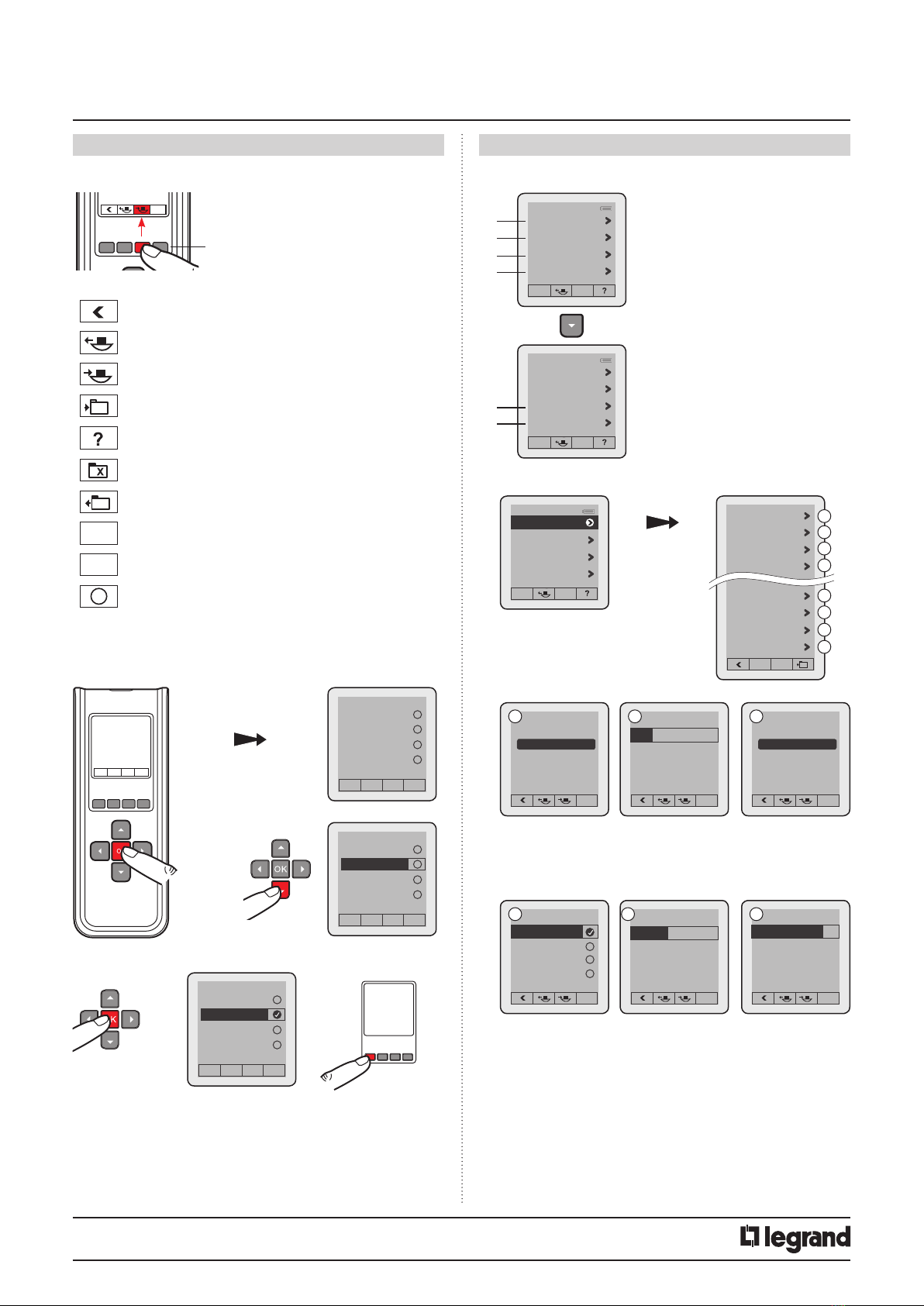
3.2.3 Advanced mode
3. NAVIGATION CONTINUED 3. NAVIGATION CONTINUED
Standby level
10%
Max: 100%
GStandby time
No standby
Max: unlimited
H
ACalibration
In order to calibrate the sensor, the surrounding light level must first
be measured using a luxmeter. The measured surrounding light level
should then be transmitted to the sensor.
Steps for setting the electric light factor:
- Put the light on and close the shutters
- Wait 2 minutes
- Measure the light level below the cell using a luxmeter
Enter this value in the tool and send it to the cell. This calibration will be
acknowledged during the next detection cycle.
Light regulation
Light regulation
B
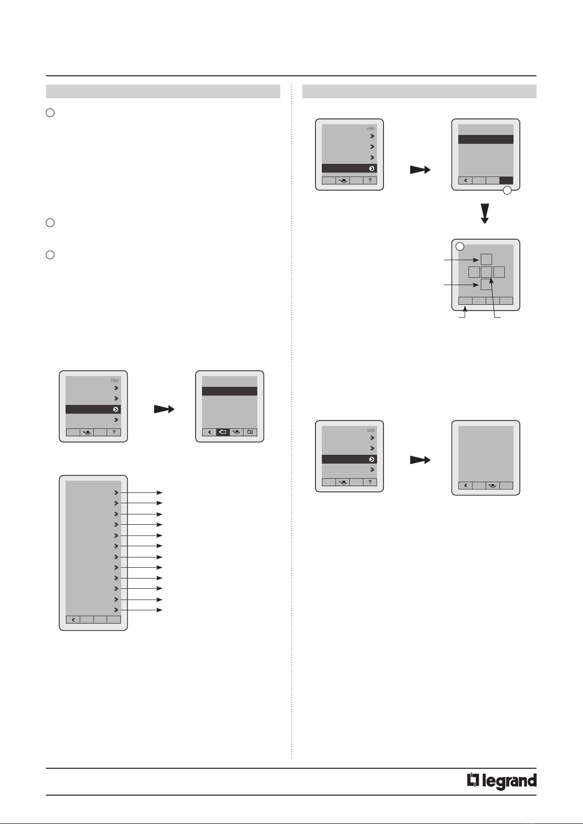
Sensor parameter
Advanced mode
Files
Sensor PnL
Advanced mode
2
Calibration
Light regulation
Provision of light
Loop type
A
D
C
B
Max. lux: 99,995
Calibration
0000 lux
A
Max. lux: 1275
Provision of light
Auto
C
Closed loop
Open loop
Loop type
Closed loop
D
ATime delay
Length of time the load is on after detection. See technical data sheet
for the associated sensor.
BSensitivity
Sets the sensor range (see technical data sheet for the associated
sensor).
CDaylight setpoint
Value at which the load switches on if the light level is less than the
setting and goes off if it is above this setpoint. The daylight setpoint
can be set up to a maximum of 1275 lux.
DMode
There are 4 different operating modes.
Auto on/Auto off mode:
Comes on automatically:
- On detection of a presence if there is insufficient natural light.
Turns off automatically:
- If no presence is detected and at the end of the time delay set.
- Or if there is sufficient natural light (regulation function activated).
Any new detection triggers an automatic switch-on if there is
insufficient light.
Walk-through:
- If no presence is detected in the 3 minutes following an initial
detection, the sensor will cut off the load after 3 minutes.
- If another movement is detected in the 3 minutes following initial
detection, the device will cut off the load at the end of the set time
delay.
Manual on/Auto off mode:
The lighting is switched on manually and switched off automatically:
- If no movement is detected at the end of the set time delay.
After switch-off, if another movement is detected within a 30-second
period, the lighting switches on automatically.
After 30 seconds, the lighting has to be switched on manually.
Partial on/Group off mode:
This mode is used to ungroup circuits that are switched on upon
detection and circuits that will be switched off at the end of detection.
Example: Upon detection I switch on the main lighting and I can
control backup lighting manually in parallel. At the end of detection,
the sensor controls switching off the main lighting and the backup
lighting circuits.
EDetection scheme
This menu concerns the detection technologies. There are several
possible types of combination.
IR and US: The sensor needs both technologies in order to switch on
the load.
IR or US: The sensor needs one of these technologies in order to switch
on the load.
HF only: The sensor needs HF technology in order to switch on the load.