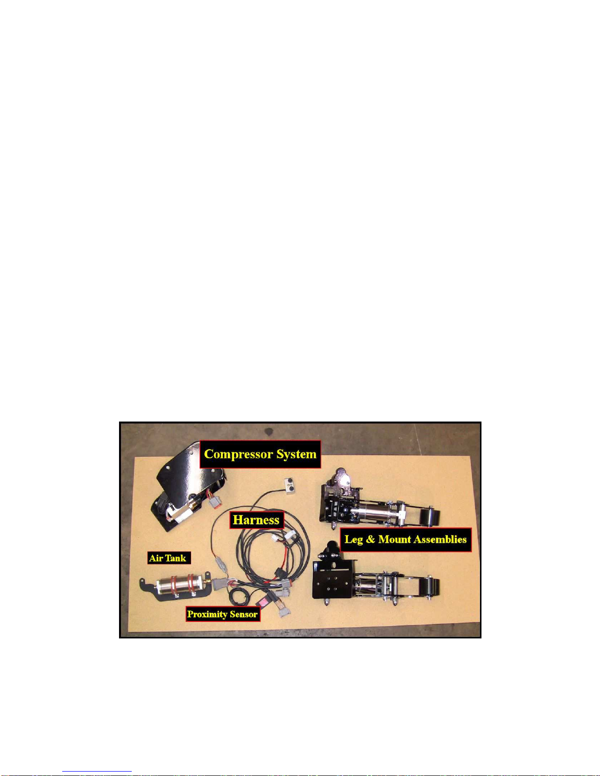
LegUp LandinGear Generation II User manual

Installation Manual
Generation II Harley
Touring Models
1988-Present
REV B
Copyright 2016, Pete Giarrusso, Inc.
D/B/A Chopper Design Services
All Rights Reserved

2

3
Table of Contents
INTRODUCTION....................................................................................4
WARRANTY............................................................................................5
INSTALLATION INSTRUCTIONS ......................................................6
PREPARE
FOR
INSTALLATION......................................................................7
CONTROL
SWITCH
BOX...................................................................................8
WIRING
HARNESS ............................................................................................10
LEG
&
MOUNT
ASSEMBLIES.........................................................................13
RUNNING
AIR
LINES........................................................................................16
SADDLEBAG
PREP
(HARD
BAGS).................................................................18
SADDLEBAG
PREP
(SOFT
BAGS)..................................................................20
INSTALL
THE
COMPRESSOR
(HARD
BAGS).............................................21
INSTALL
THE
COMPRESSOR
(SOFT
BAGS)..............................................22
MOUNT
PROXIMITY
SWITCH.......................................................................25
BIKES WITH PULLEY BOLTS................................................................................... 25
BIKE WITH NO PULLEY BOLTS (CUSH-DRIVE) .................................................. 26
WIRE
ROUTING.................................................................................................28
FINISHING
UP.....................................................................................................30
FINAL ADJUSTMENTS & MAINTENANCE MODE................................................ 31
MAINTENANCE MODE............................................................................................... 31
WHEEL ADJUSTMENT ............................................................................................... 32
TEST
RIDE...........................................................................................................37
GENERATION I UPGRADE INSTRUCTIONS.................................39
ILLUSTRATIONS.................................................................................40
SADDLEBAG DRILL TEMPLATE (HARD BAGS) .........................41
SADDLEBAG DRILL TEMPLATE (SOFT BAGS)...........................41
HARDWARE LIST................................................................................43

4
Introduction
This manual covers installation of the Generation II LegUp LandinGear system by Chopper
Design Services. This system should only be installed by a qualified technician, or those with
above average mechanical skills. If you are not SURE that you can perform this installation,
please contact us and we will help you find a qualified shop to assist you.
While the Generation II System holds your bike upright very well, you are STILL responsible
for balancing the bike! The system WILL relieve you of some of the weight of the bike and
help you avoid balance problems as you approach a stop, maneuver at slow speeds, and back
the bike up.
Improper installation will void your warranty, so please be very careful!
Thanks for choosing LegUp!

5
Warranty
Chopper Design Services warrants the LegUp system for a period of one year from date of
purchase. This warranty covers replacement parts and/or manufacturer defects. Incidental
damages or costs are the responsibility of the purchaser.
Defective parts are to be returned to Chopper Design at the address below. Purchaser must
contact Chopper Design to receive a Return Material Authorization, prior to returning defective
parts to Chopper Design.
Abuse, improper installation or use, collisions or accidents, are not covered under this warranty.
Replacement parts for this type of damage are available through Chopper Design.
Users of the LegUp system agree that Chopper Design is NOT responsible for personal injuries
or damage to property arising from the use of the system. While we believe this system to be
safe and reliable, the user is advised that use of LegUp is done so at the users’ own risk. Use of
the system implies agreement to the above statements. If you can’t agree with the above,
Chopper Design and its dealers would be happy to refund your full purchase price, before you
install the LegUp System.
Chopper Design Services
1365 Bennett Dr. #101
Longwood, FL 32750
407-834-5007

6
Installation Instructions
The LegUp® system has many components. Pleased be sure you have them all before starting
your installation.
COMPONENTS:
1) Wire Harness W Switch Box
2) Leg and Mount Assembly (L/R)
3) On-board Computer Module
4) Proximity Sensor
5) Saddlebag Mounted Compressor System
6) Hardware Bag
If you believe you are missing any parts, please contact Chopper Design at 407-834-5007, and
we will rectify the situation. Some of the parts are shown below.

7
PREPARE FOR INSTALLATION
IF YOU ARE UPGRADING FROM A GENERATION I SYSTEM, PLEASE READ THE
ADDENDUM TOWARD THE END OF THIS MANUAL ON THIS SUBJECT FIRST!
Please do not let the size of this manual intimidate you. We cover many different bikes and
circumstances here, and we feel that more pictures and more detail can only help someone
trying to install our systems. Better to have the details than want for them!
Place the motorcycle on an acceptable bike lift. You will need to keep the bike on its wheels
for most of the installation, and jack the rear wheel off the lift for some portion of the
installation. Make SURE the motorcycle is secure on the lift!
Remove the seat and disconnect the negative cable on the battery.
This manual is available at http://landingear.com/pdf/g2installhdfl-REVB.pdf . It may be easier
to see some of the pictures in color there!
We are now ready to begin!

8
CONTROL SWITCH BOX
NOTE: ON pre 1996 models as well as 2014 and up models, you will need a bracket to
mount the switch housing, which we should have supplied. In this case, remove the
bolts that secure the clutch perch clamp on the left side, install the supplied bolts
through the bracket that has the box mounted to it, through the supplied spacers, and
into the clutch perch (Blue Loctite here). Once tightened, follow the rest of these
instructions.
If your bike requires no bracket as mentioned above, remove the bolt on the top of the left
switch housing on the handlebar. Find the long chrome bolt, thread it through the Control
Switch Box, insert the spacer on the bolt and (with a drop of Blue Loctite), and thread the bolt
into the switch housing. Square the box before tightening the bolt (you may have to re-align the
mirror for clearance).
Route the wire inside the clutch lever and down the bar. Use wire ties to hold the wire to the
bar. Run the wire through the top triple tree if you can to control it. The idea here is to get the
wires neatly to the front of the tank and routed
under the tank. (It may be easier to remove the plug
end and tape the silver plug ends together for this).
We have some pictures below to give you an idea
of what this looks like.
On some bikes it is easier to loosen or remove
some of the tank mounting bolts. Make sure the
wires do not interfere with anything under the tank,
and that there is nothing that would scuff the wires.
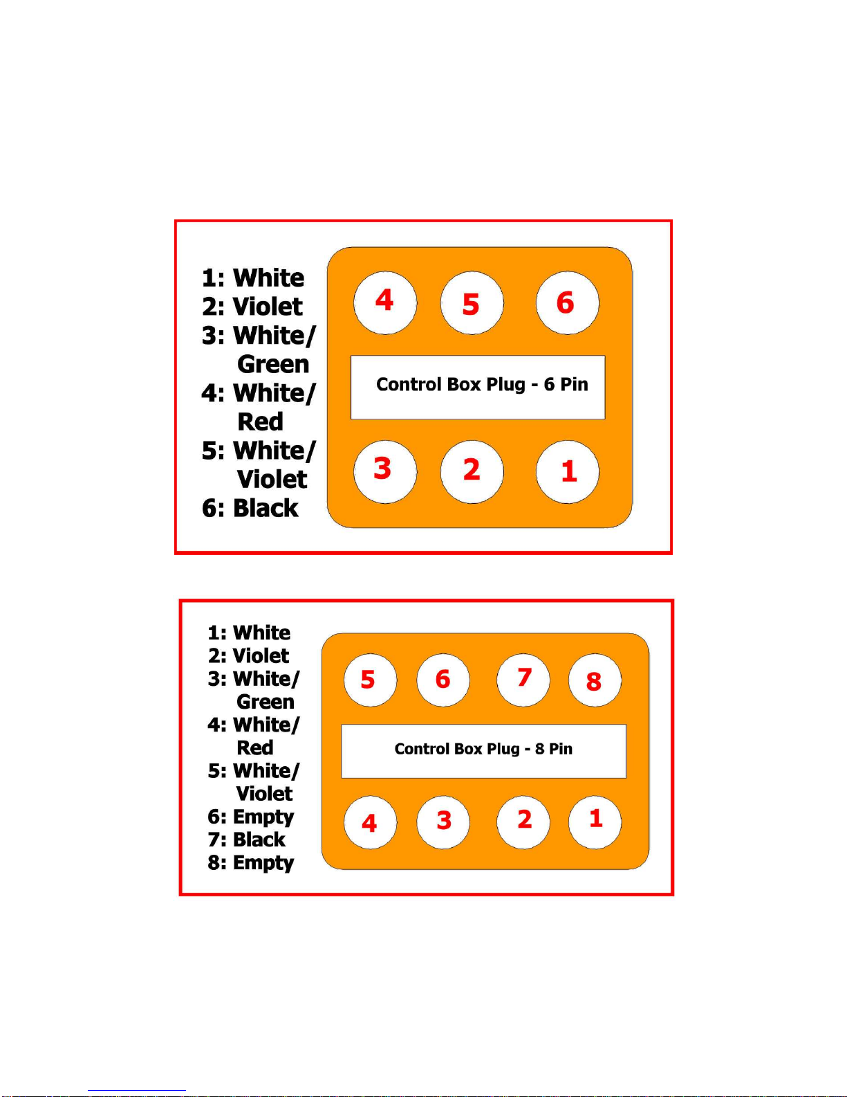
Once the wires are under the seat area, you
can assemble the plug, if disassembled,
according to the diagrams on the next page.
Some folks will have a 6-pin plug and others
will have the 8-pin version. More mistakes
occur putting these plugs together than
anything else. The pins are pushed through
the rubber holes into the plug until they click.
The pins need to be completely flush with the
edge of the plug. Then the insert is pushed
into the opening. The wiring details are found on the next page. Be VERY careful to get the
wires in the correct hole; all the colors match to the mating plug!

9
Pin Out for Handlebar Control Box Plugs

10
WIRING HARNESS
NOTE: If you are upgrading your existing Generation 1 system, please read the
addendum on this upgrade at the end of this manual, before continuing with the
wiring harness.
The next step is to route the wiring harness. The
harness and the plugs are routed mostly under the
seat. Different models have different amounts of
space in this area, and all the wires are long enough
to allow you to place the connectors in the best
place for your bike.
Remove the left side cover & saddlebag. We need
to make room for two big plugs to come through the
seat area toward the left saddlebag. On later model
bikes, this means removing the Torx bolt that holds the fuse box under the left side cover. On
earlier bikes there is more room in this area and nothing needs to be removed.
Find the two BIG plugs on the harness (12 pin with an 8
pin pigtail attached), and slide them through the seat area,
and out just below the left fender support. Leave the
remainder of the wire harness under the seat for now.
Once both plugs are through, you can pull most of the
slack out. We will be pulling these plugs back toward the
back end of the saddlebag, behind the shock.
The plug from the Proximity Sensor (3-wire) needs to
routed under the seat as well. If you have Pulley bolts on
the drive pulley (07-earlier) bring the plug up on the left
side (where the big plugs just went through). If you have a Cush-Drive bike (08-later), bring the
wire up through the right side cover and under the seat. At this point just route the wires into the
general area and plan where you would like to tie them
up safely. The Proximity sensor is not mounted yet
because we need to have power to make sure it is
placed perfectly, so just route the wire for now. You
can collect any excess wire under the seat area, when
the time comes.
Disconnect the fender plug under the seat, and plug the
double white plug in-between the plugs from the bike.

11
On some 2010 and later bikes (FLHX, FLTR), the fender plug is not like the one shown here, so
we plug into the accessory connector instead. The picture below shows this connector, under the
seat below the ECM. Remove the rubber plug and
plug the four pin (with just two wires; orange and
black) into the bikes’ accessory connector. The
double white plugs we talked about above will
NOT be found on your harness. 2014-Up have a
different plug, and we supply a 6 pin Deutsch
plug to mate with the Diagnostic Plug under the
left side cover. We will supply you with the plug
for your bike; you just have to find where the
factory hid its mate.
NOTE: If you have a pre-1996 bike, you will
have two wires (no white plug) and will need to connect these to switched 12-volt (orange)
and ground (black).
Connect the Control Switch Box plug to its mating connector under the seat (8 pin or 6 pin as
previously discussed), and plug the proximity sensor plug into its’ matching connector. Don’t
worry, the plugs only work one way… you can’t make a mistake here!
We need to find the fuse holder and the black
wire with the hoop ends and get them to the
battery. These two wires run direct power to the
compressor when it needs it. This wire should
already be under the seat area. We want to
connect the wire with the fuse holder to the
positive terminal of the battery (the battery cable
should attach closest to the battery with this
connector and any others attached after the
battery cable, as shown here). Plan where you
want the fuse holder so you can get to it if it is
ever required!
Don’t connect the black wire to the negative post yet! We will when we are ready to test the
system. Depending on the year of your bike, it may look very different than the picture here.
Don’t tie down the wires just yet; we will clean up everything later. Also, leave the left
electrical box loose (if applicable) until later as we will need to run air lines in this area.
Next, we need to secure the wires that go into the saddlebag to the left fender rail, and leave
enough wire for the plugs to reach the computer and the compressor.

12
Start by getting the wire with the 2 big plugs on it, run inside the left shock toward the back of
the bike. Next, measure 10 inches back from the 12 pin (biggest) plug and mark the wire. We
are trying to make sure we have all the
wire we need but not too much extra.
Run the wire under the chrome fender
support and tie it off to the two fender
supports. 2009 and later bikes look like
the picture at left, on others it will look a
bit different; just make sure you leave
the wire needed, and tie it off securely
and out of the way of anything that
moves or could hurt the wire.
No Matter how you need to secure the
wire, make sure you have 10 inches of
wire sticking out from the end of the
fender support, to allow us enough wire
to get what we need into the saddlebag.
You can now pull the extra wire back into the under seat area. Later we will be securing air
lines to this wire, so make sure that will be possible with your choice of how to attach this wire!
The only wire left dangling should be the proximity sensor and mount, and we will handle that
soon.

13
LEG & MOUNT ASSEMBLIES
IMPORTANT!
This manual covers our Rev B Mounting system, which replaces
the stock passenger single bolt design with our own, two bolt mounts. If you have
the earlier mounting system that clamps to existing floorboards, please see the
link below for the correct manual for your application:
http://landingear.com/pdf/g2installhdfl.pdf
First we want to remove the passenger floorboards (if installed). If your bike had pegs, you can
buy floorboards from Harley or we can supply them to you (skip to the next page!). If you have
floorboards, it is easier to remove
these while the mount is still on
the bike!
As shown at right, lift the inboard
part of the floorboard cover,
which exposes (2) pins, and soon
a ball-bearing and a spring. The
arrow shows Ben pushing one of
the pins toward the center. Do this
on both sides, but keep pressure
downward on the board to
maintain the ball-bearing and
spring that is beneath it in the
middle. Once this is done,
carefully raise the board off the
mount, catching said spring setup, and set the board & hardware aside for installation later.
In order to mount the legs in place of the passenger floorboards/pegs, we must remove the
existing rear floorboard or pegs mounts, whichever the bike is using. Depending on the year,
the bike will have one or two Allen bolts holding the now exposed mount to the bike. Once
these are removed, make sure the top and the 3
rd
hole from the top do NOT have any plastic
plugs in them.
We are now ready to mount the Legs.

14
Each leg has two pieces; we
have a mount that attaches
directly to the bike and a leg
that mounts to this piece. This
new mounting system is
MUCH stronger that Harley’s
floorboard mounts.
Find the mount as shown at
left, and (2) 3/8X1” Allen head
screws. Put a touch of Red
Loctite on the threads of the
screws and mount the bracket
to the bike (The letter ‘L’
should be readable, not upside-down… The ‘L’ is on BOTH Pieces… The two parts are
identical… The ‘L’ does NOT stand for ‘LEFT’). We are using a long, ball-end Allen bit
through the holes in the plate, but a hand Allen wrench can work just as well. These bolts need
to be very tight, because it is difficult to get to them once the leg system is installed.
Next we want to attach the leg system. First
gather 2 5/16-18 X 7/8” button-head bolts with
Nylock nuts and (2) 5/16 X 7/8” Hex Head
bolts with Nylock nuts. Make sure you have the
correct leg, raise it up to the plate you just
mounted and insert the button-head bolts into
the top holes. This should support the heavy leg
system. Install the two Nylock nuts to these
bolts (Ben is shown tightening the top bolts at
right). Do NOT get these very tight quite yet!
Now install the two hex heads into the lower
holes. If you have trouble getting to the back
hole, get the front one in place first, with its nut
attached, then you should be able to pull the leg down
to line up the back bolt. Once all the bolts and nuts
are in place, slowly snug them all down. Two ½”
wrenches are used on the bottom bolts as shown here.
Once you heave the bolts completely tight, give the
leg a good tug; it should be one with the bike!
Let’s mount the floorboard!

15
At left, you can see the leg system mounted. The
arrow points to the installed spring and ball-
bearing. Make sure this is in place and offer up
the floorboard carefully to this mount.
Just like when we removed the floorboard, we
want to slide the pins in to hold it in place. Have a
small screwdriver or something that will allow
you to push these toward the middle, through the
holes on the outside.
Carefully lower the board onto the mount, being
careful not to disturb the spring or ball-bearing.
Once in place, push each of the pins
though the board and the mount holes
on the leg system until they have about
¼” showing on both sides of the
floorboard casting. You will know you
have the correct amount if the floor-
board cover can fall back into place. If
not, make small adjustments to the
pins to center them, and make sure the
floorboard cover sits back down
nicely.
Please Note: The floorboards on our
mount only flip a small amount. This
allows cleaning if/when needed. We
would have had to make the mounts a
bit wider and higher to allow the
boards to flip up. We felt this was
unnecessary due to the fact that out leg
mounts are fixed in the same spot the
floorboards occupy when they are down.
Make sure the rubber is flat and stuck in the down position. Let’s run the air lines.

16
RUNNING AIR LINES
We need to route the air lines from the cylinders to the area near the left saddlebag. You should
find 2 long air lines of identical lengths. On the
right side of the bike, press one end into the
fitting on the back of the air cylinder. These press
in relatively easy, but a small tug will make sure
the line is seated.
Guide the line through the hole in the mount as
shown by the arrow at left (all styles have a hole
for the line); picture may not show your style
board. We now need to guide that line over to the
left side of the bike as we will be running it with
the other line, away from anything that might
damage it!
At right we have a picture of the line running
under the right floorboard mount, tied lightly to
the floorboard mount (Notice Ben is extending
the leg, so he gets the needed slack from the
line) and run under the right side cover area to
get to the other side of the bike and joining the
left line. Get the line there any way you can,
just be sure that it is secure, and cannot be damaged by anything hot or moving. Once run, you
should mark the end with masking tape as ‘RIGHT’.
Take the other line; insert it into the left
cylinder as you did on the other side. Mark the
far end as ‘LEFT’ and tie the marked ends
together with masking tape, so we can run
them together.
Check Both Sides before we move on that by
lowering and raising the legs, there is plenty of
slack for the lines. Readjust your wire ties if
need be, but make sure they work properly to
avoid headaches later!

17
We want to run the lines behind or through the
area under the left side cover. Here Ben ties the
two together on their way toward the back. We
want to guide these up to where the wire
running along the fender support is. We like to
tie two loose wire ties to that wire, and run the
air lines through them. We will adjust and
tighten everything a bit later.
The main concern here is to make sure the lines
are run where they will be safe from the belt,
exhaust pipes, or anything that could hurt them.
Here is a picture of the lines running along the bottom of the fender support, being tied off to
the big wire running toward the back. You can tie them to anything you like, as long as they are
safe and out of the way! Then you can start working back tying off the lines. Tighten the lines
under the fender strut, and just leave the end
wild for now!
These are air lines, so tie them off
snugly. Careful though; too tight could
restrict the air flow.
Once we have everything tied up, we want to
make a loop with the extra line. This will keep
the lines the same length (which allows the
wheels to come down evenly) and makes it
easier to remove and install the bags. Just
take the lines as shown here, make a nice
loop, and tie them off to each other. Not too
tightly as we want the loop to be able to
move as you try to remove or install the bags.
Next we want to prepare the saddlebag. This
requires us to drill a few small holes to allow
lines or fittings to travel through the bag to
get to the compressor system.

18
SADDLEBAG PREP (HARD BAGS)
NOTE: If you have soft bags (Road King Classics and Customs), skip to the next
section; ‘Saddlebag Prep (Soft Bags)’.
On one of the last pages of this manual, you will
find a drilling template for Hard Bags. Carefully cut
the template out (making sure it is to scale), and
tape it to the inside of the left saddlebag as shown.
The saddlebag is curved, so just bring the straight
lines to the edges where they start to curve and you
will be fine. There is a margin of error here, so
don’t worry!
Use a small bit to start (1/8” of so) and drill through
the pilot hole on the template. Once these are done,
the final drill size is 3/8” or
½”
depending on the
fittings (we supply 2 different sizes from 2 different
vendors). If you are unsure, drill a 3/8” hole, if it is too small, move up to
½”
.
Once the holes are in place, find the bulkhead fittings. The 90 degree part stays on the outside
of the bag with the straight part inside.
Start with the lower hole, and tighten the fitting. No
reason to make it too tight, there is no chance for leaks
here, and the elbow spins to make it easier to attach the
lines.
Once the bottom fitting is in place, install and tighten the
top fitting. Now the bag is ready!
It is time for a test fit! Put the saddlebag on the rail and
lean it out as shown here. Find the line you marked as
right, and insert it in the bottom fitting; the other
in the top fitting. Now attach the bag, and make
sure the lines are in no sort of bind or in danger of
being damaged by anything!

19
The last thing we need to do is
create a small notch for the wires to
get through when the bag is closed.
We use a rotary burr, but you could
use a file or a small saw, to cut the
notch you see here.
What we want to have is a notch
about 3/8” wide by about 3/8” deep.
This small slot will have no
negative bearing on the weather-
tight nature of the bag, but it will
keep the wire from being hurt as
you open and close the bag over
time.
At the top of the bag, about 1” to
the left of the bail nut (the bolt that
holds the bag on) is where you want to place the relief. A bit left or right makes little difference,
but this wire goes down into a relief cut in the top of the compressor cover, so the more accurate
you are here, the better!
Make sure that the wire, when placed into the notch, as at or below the top surface of the bag,
and you are go to go!
Skip the next section on ‘Soft Bags’ and go to ‘Install the Compressor (Hard Bags)’.

20
SADDLEBAG PREP (SOFT BAGS)
NOTE: If you have hard bags (all but Road King Customs & Classics), skip to the next
section; ‘Install Compressor (Hard Bags)’.
On bikes with Harley® soft bags (Road King
Customs & Classics), we used to mount the air
tank outside the saddlebags, due to how narrow
the soft bags are. Recently, we decided to use
the compressor from the Softail® system, which
has the air tank mounted above the compressor
as you see here.
If you have the older setup, you can find the
documentation at:
http://landingear.com/pdf/g2installhdfl.pdf.
The only thing we need to do to prepare the saddlebag is to drill a required hole in the
saddlebag back. The hole allows the air lines to get in and out of the saddlebag, and also allow
easy removal of the bag.
First we need to find, near the end of the
manual, the drilling template for soft bags.
Carefully cut this template out, and tape it
to the inside of the left saddlebag, as seen
in the next picture. The flat bottom of the
template lines up with the bottom of the
bag, just before it turns under, while the
curve should fit nicely as seen here. The
upper left angle should fit inside the line
where the leather meets the hard back.
There is a margin for error here so be
careful but not paranoid. Once placed,
drill using a 5/16” bit, ONLY THE TOP
hole of the template. We used to use both
holes when the tank was outside. Now
skip to the section on installing the
compressor (Soft Bags).
Table of contents
Popular Motorcycle Accessories manuals by other brands

hepco & becker
hepco & becker 740037 installation instructions

Innovate Motorsports
Innovate Motorsports MTX-L user manual

DUCATI Performance
DUCATI Performance 96780851A manual

R&G
R&G FI0094BK Fitting instructions

Makita
Makita DFJ210 instruction manual

Thunderbike
Thunderbike 61-74-190 installation instructions