LegWorks ATK HydraPro User manual

ATK HydraPro™
INSTRUCTIONS FOR USE

English ATK HydraPro | Instructions for Use
© Copyright LegWorks 2019 HYD-IFU-02
2
TABLE OF CONTENTS
PRODUCT DIAGRAMS..................................................................................4
DESCRIPTION AND PURPOSE.....................................................................5
PRODUCT SPECIFICATIONS.........................................................................7
ATK HydraPro
ATK HydraPro with Stance Flexion
OUR TECHNOLOGY.....................................................................................9
SAFETY.........................................................................................................10
User Instructions
SETUP and OPERATION.............................................................................11
Connections
Bumper Selection Guidelines
Bumper Adjustment Instructions
Sagittal Plane Alignment
AutoLock Mechanism
Flexion Stop
Friction Mechanism
Friction Mechanism Removal
Friction Mechanism Installation
Adjustable Extension Assist
Cover
Manual Lock
MAINTENANCE............................................................................................21
User
Prosthetist
WARRANTY..................................................................................................22
Exclusions
Liability
Disposal
ORDERING AND CONTACT INFO.............................................................24

English ATK HydraPro | Instructions for Use
© Copyright LegWorks 2019 HYD-IFU-02
3
FIGURES
1. ATK HydraPro Anterior Overview...........................................................4
2. ATK HydraPro Posterior Overview.........................................................4
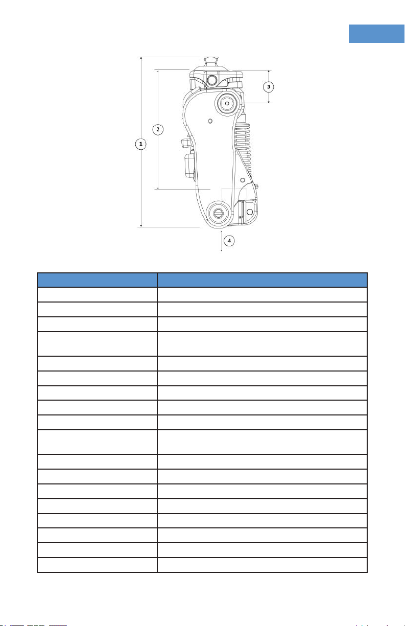
3. ATK HydraPro Build Height Diagram.....................................................7
4. HYD-PA-02 Technical Specications......................................................7
5. ATK HydraPro w/Stance Flexion Build Height Diagram..........................8
6. HYD-SF-02 Technical Specications.......................................................8
7. Stance Phase Function............................................................................9
8. Adjustable Stance Flexion Adaptor Assembly....................................11
9. Proximal Connection.............................................................................12
10. Sagittal Plane Alignment.....................................................................13
11. Lock Spring Set Screw.........................................................................13
12. Absence of Flexion Stop.....................................................................14
13. Malpositioned Flexion Stop...............................................................14
14. Appropriate Flexion Stop...................................................................14
15. Friction Mechanism.............................................................................15
16. Friction Mechanism Cap and Disc Springs.......................................15
17. Friction Mechanism Removal.............................................................16
18. Friction Mechanism Installation.........................................................17
19. Adjustable Extension Assist................................................................18
20. ATK HydraPro Cover Removal............................................................19
21. ATK HydraPro AutoLock Release.......................................................19
22. Manual Lock.........................................................................................20

English ATK HydraPro | Instructions for Use
© Copyright LegWorks 2019 HYD-IFU-02
4
PRODUCT DIAGRAMS
Fig. 1
ATK HydraPro Anterior Overview
Fig. 2
ATK HydraPro Posterior Overview

English ATK HydraPro | Instructions for Use
© Copyright LegWorks 2019 HYD-IFU-02
5
DESCRIPTION & PURPOSE
The primary components and adjustments are identical across all knee
versions. Specic dierences in components, features and adjustments are
indicated within the document by notation of the relevant product code.
INTENDED USE:
• These instructions are for use by the prosthetist tting and/or
maintaining the device.
• Both device models are intended for single person use.
• Both device models are to be used exclusively as part of an external
lower-limb prosthesis.
• Both device models are developed for everyday use and must not be
used for unusual activities, such as extreme sports.
• HYD-PA-02 is designed exclusively for Knee Disarticulation or
Transfemoral amputees.
• HYD-SF-02 is designed exclusively for Transfemoral amputees.
Ensure that both the prosthetist and the user have read and understood
the Instructions for Use, especially the safety information. If the user experiences
any issues with the device, they should immediately contact their prosthetist.
If the prosthetist experiences any issues, immediately contact LegWorks.
Last updated: 2019-08-01
• Please read this document carefully.
• The safety instructions are to be followed by both the prosthetist and
the user.
PRODUCT CODES
This instructional manual covers all current versions of the ATK HydraPro:
Product Name Product Code
ATK HydraPro HYD-PA-02
ATK HydraPro with Stance Flexion HYD-SF-02

English ATK HydraPro | Instructions for Use
© Copyright LegWorks 2019 HYD-IFU-02
6
SCOPE OF DELIVERY
• ATK HydraPro Device
• ATK HydraPro Device Cover
• Instructions for Use (IFU) manual
• Quick Reference Card (QRC)
• ATK HydraPro User Guide
• Extension Assist Springs:
• medium stiness (pre-installed)
• strong stiness
• weak stiness
• HYD-SF-02 only: Posterior Stance Flexion Bumpers: Firm, Medium
(pre-installed), and Soft stiness
FUNCTION
• Stance Phase Control: AutoLock Technology
• Swing Phase Control: Adjustable variable friction resistance (Variable
Cadence Controller) and spring extension assist
• Design:
• HYD-PA-02 and HYD-SF-02: Waterproof and corrosion resistant in
both freshwater and saltwater (e.g. shower, pool, ocean)
• Activity Level: Suitable for K3 and K4 activity levels
INDICATIONS
• Transfemoral (both device models), Knee Disarticulation (HYD-PA-02
model only)
• K3-K4 mobility level (primary prosthesis)
• Secondary prosthesis (bathing or water leg)
WEIGHT LIMIT
• HYD-PA-02 and HYD-SF-02 have been tested and passed to the 150kg
(330 lb) P8 ISO 10328:2006 standard
DESCRIPTION & PURPOSE

English ATK HydraPro | Instructions for Use
© Copyright LegWorks 2019 HYD-IFU-02
7
Product ATK HydraPro
Part # HYD-PA-02
Amputation Level Transfemoral, Knee Disarticulation
Activity Level K3-K4
Material Advanced Fiber-Reinforced Composite, Stainless
Steel, Titanium
Maximum Body Weight 150kg (330 lb)
Total Fitted Height (1) 186mm (7 5/16 in)
Eective Fitted Height (2) 125mm (4 15/16 in)
Fitted Height (3) 24mm (15/16 in)
Tube Clamp Depth (4) 45mm (1 3/4in)
Attachment Point to First
Axis Oset 9mm Posterior Oset
Product Weight 1,052g (2.32 lb)
Ground Clearance 11mm (7/16 in)
Proximal Connection Pyramid Adaptor
Swing Phase Control Hydraulic Variable Cadence Controller
Stance Phase Control AutoLock Technology (Patented)
Axes Four Axes
Flexion Angle (minus socket) 150 degrees
Distal Connection 30mm Tube Clamp
Fig. 3
ATK HydraPro HYD-PA-02 Build Height Diagram
Fig. 4
ATK HydraPro Premium HYD-PA-02 Technical Specications

English ATK HydraPro | Instructions for Use
© Copyright LegWorks 2019 HYD-IFU-02
8
Product ATK HydraPro with Stance Flexion
Part # HYD-SF-02
Amputation Level Transfemoral
Activity Level K3-K4
Material Advanced Fiber-Reinforced Composite, Stainless
Steel, Titanium
Maximum Body Weight 150kg (330 lb)
Total Fitted Height (1) 201mm (7 15/16 in)
Eective Fitted Height (2) 141mm (5 9/16 in)
Fitted Height (3) 40mm (1 9/16 in)
Tube Clamp Depth (4) 45mm (1 3/4in)
Attachment Point to First
Axis Oset 19mm Posterior Oset
Product Weight 1,242g (2.74 lb)
Ground Clearance 11mm (7/16 in)
Proximal Connection Pyramid Adaptor
Swing Phase Control Hydraulic Variable Cadence Controller
Stance Phase Control AutoLock Technology (Patented)
Axes Four Axes
Flexion Angle (minus socket) 150 Degrees
Distal Connection 30mm Tube Clamp
Fig. 5
ATK HydraPro HYD-SF-02 Build Height Diagram
Fig. 6
ATK HydraPro HYD-SF-02 Technical Specications

English ATK HydraPro | Instructions for Use
© Copyright LegWorks 2019 HYD-IFU-02
9
The ATK HydraPro is suitable for users in mobility classes 3-4. Adjustments
can be made to the Hydraulic VCC to control heel rise and terminal impact
levels, resulting in smooth and responsive swing dynamics at dierent walking
speeds. The AutoLock Mechanism ensures optimal stability when negotiating
uneven terrain. Simple conversion to manual lock mode is also possible for
situational use.
OUR TECHNOLOGY
The ATK HydraPro utilizes a proprietary stance-phase control mechanism
(AutoLock Technology) and swing-phase control mechanism (Hydraulic Variable
Cadence Controller or Hydraulic VCC). The mechanisms comprise a 4-linkage
(4-bar) kinematic chain. The AutoLock Technology is based on a knee lock
that is automatically engaged in late-swing-phase for extra safety. The knee
remains securely locked until mid-to-late stance-phase when it is disengaged
for an eortless swing-phase initiation.
The Hydraulic VCC utilizes a combination of hydraulic damping, a variable
friction system, and an optimized extension assist spring for ecient gait at
multiple walking speeds. The 4-bar kinematic arrangement of the ATK HydraPro
mechanism results in swing-phase foot clearance comparable to 4 and 6 bar
polycentric knee mechanisms.
Fig. 7
Stance Phase Function

English ATK HydraPro | Instructions for Use
© Copyright LegWorks 2019 HYD-IFU-02
10
Both device models of the ATK HydraPro should only be t by a qualied
professional.
In the nal stage of quality control, all ATK HydraPro units undergo functional
testing to ensure optimal performance standards are met. As a result, the
product may ship with visible indentation marks on the pyramid.
If there are any visible changes, wear and tear, or functional limitations, replace
the part, or contact the manufacturer for a replacement part or servicing request.
Please make sure the user is competent in handling of their prosthesis before
leaving the premises. Failure to observe this warning may cause the user to fall.
Please be aware of nger traps in the knee joint at all times.
The user should immediately report any changes, i.e. excessive movement in
the knee during stance-phase, inconsistent locking, etc. to their prosthetist.
Always use a handrail when descending stairs and on downward slopes if
available.
Any excessive changes in heel height may adversely aect the stability of the
knee. Care should be taken while carrying heavy loads.
USER INSTRUCTIONS
Do not adjust your knee or change your alignment. Alert your prosthetist
immediately to any suspicious sounds from the knee (clicking, crackling, etc.).
Inspect your prosthesis often, clean with a towel. Do not tamper with any
screws on the knee.
Observe all the above points, otherwise the warranty becomes null and void.
SAFETY

English ATK HydraPro | Instructions for Use
© Copyright LegWorks 2019 HYD-IFU-02
11
CONNECTIONS
The proximal connection consists of a M10 bolt that is attached directly to a
male pyramid adaptor (Fig. 9).
HYD-SF-02 ONLY - ADJUSTABLE STANCE FLEXION ADAPTER
The ATK HydraPro with Stance Flexion features a proximal articulating pyramid
adapter with anterior and posterior bumpers that compress upon loading,
providing up to 12 degrees of total movement throughout stance phase.
The HYD-SF-02 is shipped with the adapter pre-installed with the medium
grade posterior bumper inserted.
BUMPER OPTIONS
SETUP AND OPERATION
Anterior or Posterior Bumper Color Hardness
Anterior Blue Medium (pre-installed)
Posterior Black Soft
Posterior Blue Medium (pre-installed)
Posterior Gray Firm
1. Top Adaptor Assembly
2. Anterior Bumper
3. Posterior Bumper
4. Plate
5. M10 Washer
6. For HYD-SF-02: 16mm Hex
Head M10 Adaptor Screw
Fig. 8
Adjustable Stance Flexion Adaptor Assembly

English ATK HydraPro | Instructions for Use
© Copyright LegWorks 2019 HYD-IFU-02
12
BUMPER SELECTION GUIDELINES
If patient experiences excessive motion or a sensation of instability with the
pre-installed bumper: select the rm posterior bumper (gray).
If patient experiences heel strike as too rigid: select the soft posterior
bumper (black).
BUMPER ADJUSTMENT INSTRUCTIONS
1. Turn M10 bolt to remove proximal assembly.
2. Select the desired posterior bumper and insert into channel as shown.
3. Ensure that the anterior bumper is properly seated into channel as shown.
4. Install combined assembly onto knee using M10 bolt with washer
while ensuring that bumpers remain properly aligned and housed
within the adapter while tightening the bolt.
5. Torque M10 bolt to 30Nm / 22 ft lb.
6. Check prosthetic alignment (see section 3).
For the distal connection, ensure the
30mm pylon is fully inserted. Tighten
pylon clamp screw to 120Nm (9 ft lb)
by turning the bolt with a 6mm hex
bit torque wrench.
If a loud creaking sound occurs at
heel strike, apply a small amount of
multi-purpose oil or silicone spray
to the surface area of the pylon that
rests within the knee’s tube clamp.
Fig. 9
Proximal Connection
Using a torque wrench, tighten
the M10 bolt to 30 Nm (22ft lb)

English ATK HydraPro | Instructions for Use
© Copyright LegWorks 2019 HYD-IFU-02
13
SAGITTAL PLANE ALIGNMENT
Position the knee’s rst axis 20mm posterior
to the plumb line bisecting proximal aspect of
socket (baseline recommendation).
To increase ease of unlocking, increase toe load:
• Shift knee posterior
• Plantarex foot
• Increase socket exion
Tighten pylon clamp of knee to 12Nm (9 ft lb)
Fig. 10
Sagittal Plane Alignment
AUTOLOCK TECHNOLOGY™ MECHANISM
Fig. 11
Lock Spring Set Screw
Turn by 1/4
turn increments
Turn by 1/4
turn increments

English ATK HydraPro | Instructions for Use
© Copyright LegWorks 2019 HYD-IFU-02
14
A exion stop must be provided between the socket and the distal posterior
portion of the knee to prevent hyper exing of the knee and damage to internal
mechanisms of knee.
In maximum exion, it is vital that a exion stop is in eect and contacts the
ATK HydraPro in the proper location. See examples below:
FLEXION STOP
Fig. 12
Absence of Flexion Stop
Fig. 13
Malpositioned Flexion Stop
Fig. 14
Appropriate Flexion Stop
Incorrect:
No contact point exists between socket and
lower body of knee in maximum exion.
Damage to knee may occur.
Incorrect:
Socket is in direct contact with extension
assist spring assembly in maximum exion.
Damage to knee may occur.
Correct:
Socket naturally contacts the body of knee
below the spring assembly. A exion stop
(e.g. crepe) may need to be axed to socket
to achieve this.
Alternately, a exion stop may need to be
axed to the knee’s pylon adaptor and the
sidewalls surrounding the extension assist
spring.

English ATK HydraPro | Instructions for Use
© Copyright LegWorks 2019 HYD-IFU-02
15
Minimum Friction Setting (MFS): failure to achieve MFS
causes mechanism to loosen and fall o with use.
Ensure the friction mechanism caps and disc springs
are not loose i.e. able to rattle or make noise when
tapped with a nger.
If user requires a more free-swinging knee, the friction
mechanism assembly can be removed (Fig. 21) and
stored for later use; this does not aect the integrity
of the knee’s assembly.
FRICTION MECHANISM
Turn by 1/4
turn increments
Turn by 1/4
turn increments
Fig. 15
Friction Mechanism
Gap present with
disc springs in slight
compression
Fig. 16
Friction Mechanism Cap and Disc Springs
Over-tightening the friction mechanism may keep the knee from reaching
full extension, preventing the AutoLock Technology from locking.

English ATK HydraPro | Instructions for Use
© Copyright LegWorks 2019 HYD-IFU-02
16
If user requires a more free swinging knee, remove the friction mechanism
by loosening the 4mm hex bolt until threading releases. Carefully remove
and re-assemble to avoid misplacing parts.
FRICTION MECHANISM REMOVAL
Fig. 17
Friction Mechanism Removal
1. Turn the 4mm hex head bolt counter
clockwise while maintaining a rm
grip on the friction mechanism
threaded cap on the opposite side.
Turn until the threading releases.
2. Pull the friction mechanism cap,
the two disc springs and the
threaded bolt out of the knee while
maintaining pressure on the friction
mechanism threaded cap on the
opposite side.
3. Carefully gather threaded cap and
two disc springs.
Re-assemble friction mechanism to
avoid losing parts.

English ATK HydraPro | Instructions for Use
© Copyright LegWorks 2019 HYD-IFU-02
17
FRICTION MECHANISM INSTALLATION
Fig. 18
Friction Mechanism Installation
1. Position friction mechanism threaded caps so that
the post engages with the opening on the mating
surface of the knee.
2. Ensure disc springs openings are centered over the
opening of the interior cylinder of the knee.
3. Insert friction screw with friction mechanism cap
and washers and tighten until threading engages
with the opposite side.
4. Turn knee so friction mechanism threaded cap is
facing up, apply Loctite 242 or similar. Allow to
penetrate threading of screw.
5. Tighten friction unit bolt head until there is no
rattling or audible noise when tapping the opposite
side friction mechanism cap with a nger. There
should be a gap present with the disc springs in
slight compression.
This is the minimum friction setting.

English ATK HydraPro | Instructions for Use
© Copyright LegWorks 2019 HYD-IFU-02
18
The knee joint is shipped with medium stiness extension assist spring
(white) pre-installed (Fig. 19).
ADJUSTABLE EXTENSION ASSIST
SPRING ASSEMBLY
Insert spring base into chosen
spring.
WEAK
BLUE
MED.
WHITE
STRONG
RED
EXTENSION ASSIST BIAS OPTIONS
Watch out for nger
traps when compressing
the spring.
POSTERIOR
VIEW
REMOVAL
Insert athead screw-driver below
the spring base and above horizontal
shaft. Compress spring up-ward and
pull outward.
INSTALLATION
Align horizontal groove of extension
assist base with horizontal shaft
prior to closing spring assembly.
Fig. 19
Adjustable Extension Assist

English ATK HydraPro | Instructions for Use
© Copyright LegWorks 2019 HYD-IFU-02
19
The cover protects the ATK HydraPro, as well the user’s clothes. The
ATK HydraPro can be operated without the cover. Should the cover be bro-
ken, it can be easily ordered and replaced.
COVER
To remove cover, grasp and separate
sides of cover from knee before pulling
away from the anterior location of the
joint (Fig. 20).
Cover should be removed when attaching
the knee to a socket and/or adjusting the
set screws for alignment.
Fig. 20 ATK HydraPro Cover Removal
COVER O-RING
The cover has an o-ring to minimize noise.
Ensure the o-ring is present. The bridge
of the cover should be connected into the
opening of the main body of the knee.
AUTOLOCK RELEASE
Activation of the “AutoLock Release”
unlocks the knee which initiates exion af-
ter sitting with the knee in AutoLock mode
(locked and extended). Simply push the
‘AutoLock Release’ to either side to unlock
and ex the knee.
Fig. 21
ATK HydraPro AutoLock Release

English ATK HydraPro | Instructions for Use
© Copyright LegWorks 2019 HYD-IFU-02
20
When setting up the prosthesis, ensure the top of the cover does not
come in contact with the socket and that a gap exists when the knee is fully
extended. In case a gap does not exist, modify the socket or grind down the
cover until a gap is evident. Ensure that there is no possibility of cosmetic
coverings or clothes getting caught between the cover and socket, otherwise
the knee will not properly lock. This could lead to fall and injury.
Turning the manual lock knob clockwise to the vertical position securely en-
gages the knee lock when knee is fully extended. Turning it to the horizontal
position allows for AutoLock operation. The manual lock can be engaged with
knee exed or fully extended. Activating manual lock when knee in slightly
exed is dicult and should be avoided.
MANUAL LOCK
Fig. 22 Manual Lock
The manual lock screw is factory set. DO NOT adjust unless MANUAL LOCK
disengages when in use. To adjust, use a 4mm hex key at the front and 10mm
socket wrench from the rear of the knee after removing the extension assist
spring (Fig. 16). While the knee is fully extended and locked, tighten using hex
key in 1⁄4 turn (clockwise) increments and re-test the performance. Repeat as
needed. If manual lock knob becomes too tight to turn or if clicking occurs,
loosen by 1/8 turn.
Other manuals for ATK HydraPro
1
Table of contents
Other LegWorks Medical Equipment manuals