lehman Trikes CrossBow Victory Vision 2009 User manual

2009+
Victory Vision Models
Installation Instructions
April 2014
125 Industrial Drive | Spearfish, SD 57783 | Toll Free 888.3WHEELS
w w w . l e h m a n t r i k e s . c o m

2
CLUTCH VALVE
CLUTCH MODULATION VALVE INSTALLATION
1. Rotate the handlebars all the way to the right (full
left hand turn position).
2. Remove push pins in front edge of side covers
(save).
3. Remove side covers (L & R).
4. See Fig. 1. Apply protective plastic to motorcycle
tank as shown.
5. Remove clutch reservoir cap using Phillips
screwdriver.
6. Using brake bleeder, suck out all clutch fluid from
reservoir.
7. See Fig. 2. Using brake bleeder and 6mm
wrench, suck out remaining clutch fluid from the
system as shown.
8. See Fig. 3. Install (1) ball to (1) modified banjo
bolt .
• (1) Ball (S001508)
• (1) Modified Banjo Bolt (S001502)
9. See Fig. 3. Install (1) seat to banjo bolt using 1/8”
Allen wrench.
• (1) Seat (S001507)
Fig. 1
Fig. 2
Fig. 3
Banjo BallSeat

3
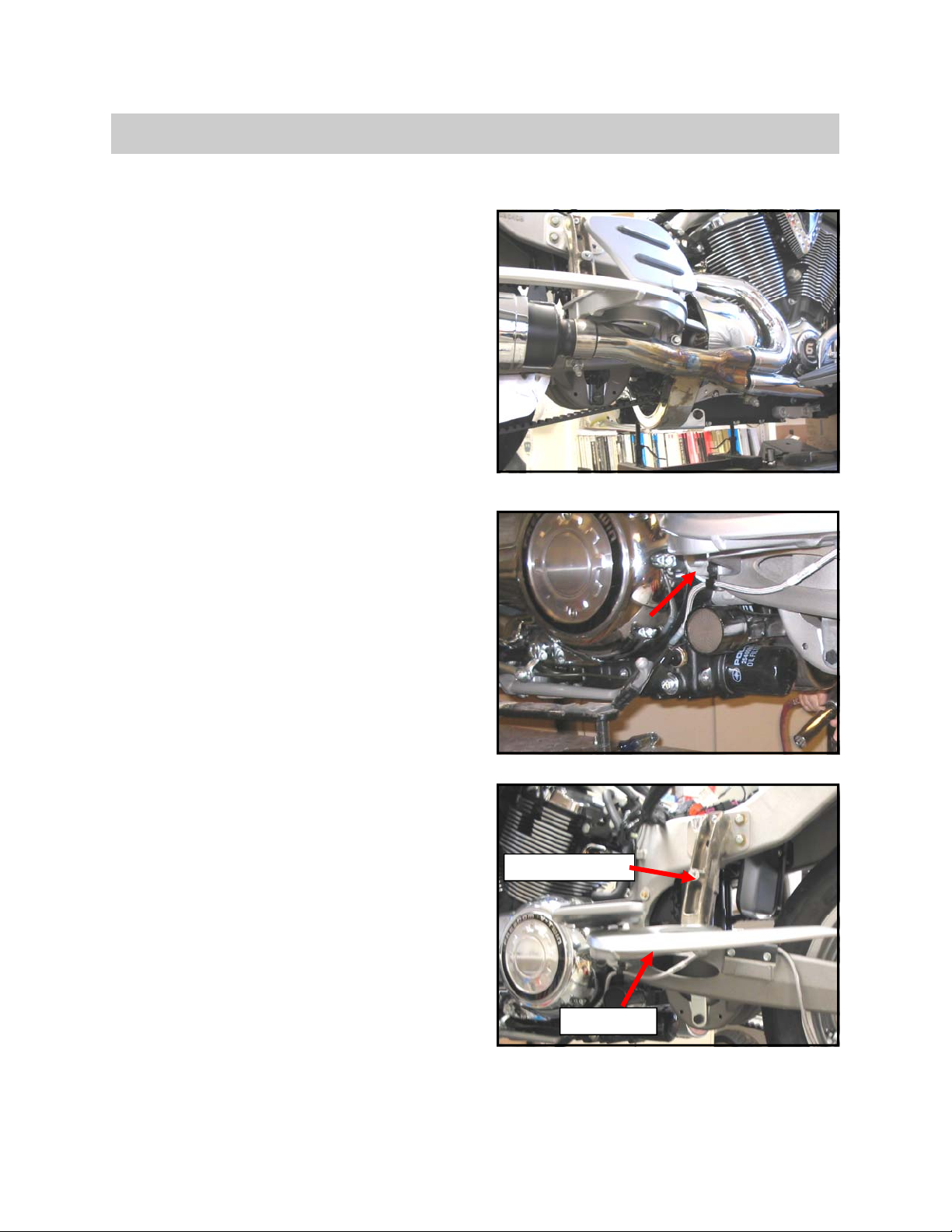
10. See Fig. 4. Using a silver sharpie, mark the loca-
tion of the cross-drilled holes on the assembled
banjo bolt as shown.
11. Remove OEM banjo bolt from clutch reservoir us-
ing 12mm wrench. Save banjo bolt in identified
container as these will go to the tech center for
modification.
• (1) OEM Banjo Bolt (save)
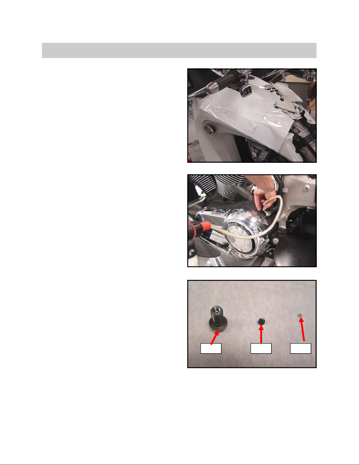
12. See Fig. 5. Install assembled banjo bolt to clutch
reservoir as shown using 12mm wrench.
13. Torque and mark banjo bolt to 16 ft. lbs using
12mm wrench.
NOTE: After torque is applied, make sure that the
cross-drilled holes are lined up with the banjo
adaptor as shown (Fig. 00-13). If the holes are not
lined up with the adaptor the clutch will not oper-
ate properly.
14. Fill clutch reservoir with DOT 5.1.
15. See Fig. 6. Bleed the clutch system as shown us-
ing brake bleeder.
16. Depress the clutch lever slowly and repeatedly
making sure all air bubbles are out of the system.
This can take some time. Make sure all the bub-
bles are out, even micro-bubbles.
17. Fill clutch reservoir to top of sight glass with DOT
5.1
18. Re-install reservoir cap using Phillips screw-
driver.
Fig. 5
Fig. 6
PART # PART DESCRIPTION TORQUE
S001502 BANJO BOLT 16 FT LBS
Fig. 4
CLUTCH VALVE

4
REAR DISASSEMBLY
1. See Fig. 1. Remove rear license plate bracket
using 4mm Allen head socket.
• 2 screws and bracket (save)
2. Remove seat.
3. Disconnect wire harness from tour pack.
4. See Fig. 2. Remove tour pack using 13mm
socket and 12” extensions.
• 4 Bolts (save)
5. Open saddlebags. Remove and save owners
manual.
6. Remove taillight valence. Ensure clips are re-
tained with valence.
7. See Fig. 3. Remove exhaust valence as shown
using 4mm long Allen head socket. Save (6)
bolts.
8.
Fig. 1
Fig. 2
Fig. 3
DISASSEMBLY

5
DISASSEMBLY
SADDLE BAG REMOVAL ( RH SIDE FIRST )
1. See Fig. 1. Remove lower saddle bag access
panels (L & R) using 4mm Allen head socket.
• 5 screws each side L & R (save)
2. See Fig. 2. Remove (5) bolts from rear of sad-
dle bag as shown using 10mm socket and
4mm Allen socket (front bolt).
• 3 bolts (save)
3. See Fig. 3. Remove (2) lower bolts from rear of
saddle bag as shown using 10mm socket.
4. Remove (2) lower nuts from front studs using
10mm socket and 6” extension.
Fig. 1
Fig. 2
Fig. 3

6
DISASSEMBLY
5. See Fig. 4. Remove (4) latch assembly bolts.
Remove latch assembly using 10mm socket.
• 4 bolts (save)
6. See Fig. 5. Remove (3) bolts from front of sad-
dle bag using 13mm socket.
7. See Fig. 6. Remove (2) bolts from upper sad-
dle bag using 13mm socket.
Fig. 6
Fig. 4
Fig. 5

7
DISASSEMBLY
8. See Fig. 7. Unhook wire harness as shown.
9. Remove top bolt from saddle bag using 13mm
socket (located behind latch assembly).
10. Remove rear-most bolt from saddle bag using
10mm socket (lower outside of taillight).
11. See Fig. 8. Remove (2) relays from saddle bag
using 10mm socket.
12. See Fig. 9. Remove striker from saddle bag as
shown using T-20 Torx Bit.
Fig. 8
Fig. 9
Fig. 7

8
DISASSEMBLY
13. Repeat steps 1 thru 13 for removal of left side
saddle bag.
14. See Fig. 10. Remove air shock fill valve using
7/8” socket.
15. Re-install nut to fill valve.
16. See Fig. 10. Remove and save left and right side
cover grommets as shown.
17. See Fig. 11. Remove diagnostic cable and grom-
met as shown.
18. Remove main wire harness connector from frame.
19. Remove saddlebag from bike,
Fig. 10
Fig. 11

9
DISASSEMBLY
DISASSEMBLY
1. Remove LS heat shield using 10mm socket.
• (2) Band Clamp (save)
2. See Fig. 1.Remove and save RS heat shield us-
ing 10mm socket.
• (1) RS Heat Shield (save)
• (1) Clamp (save)
• (1) Bolt (save)
3. Remove Left and Right side mufflers and save
using 15mm socket on front clamp and 10mm
socket on rear clamp.
• (1) LS Muffler (save)
• (1) RS Muffler (save)
4. Remove Left Side extension pipe using 15mm
socket. Save clamp.
• (1) Clamp (save)
5. See Fig. 2. Remove left and right side pivot shaft
nuts as shown using 24mm socket. Save 1 nut
and 2 washers (Fig. 10-16).
• (1) Pivot Shaft Nuts (save)
• (2) Pivot Shaft Washer (save)
6. See Fig. 3. Remove Left Side rollover brace using
10mm socket and 6mm allen head socket.
7. See Fig. 3. Remove rollover brace from floor
board using 6mm allen head socket. Save
brace, discard floor board .
• (1) LS Rollover Brace (save)
8. Repeat steps for Right Side rollover brace re-
moval.
Fig. 1
Fig. 2
Fig. 3
Floorboard
Rollover Brace

10
DISASSEMBLY
9. See Fig. 4. Remove taillights using 4mm allen
head socket. Disconnect and place on top of
tail section as shown
• (5) Bolts (save)
10. See Fig. 5. Remove reinforcement plate using
10mm socket (Fig. 10-20).
• (2) Bolts (save)
11. Remove tail section using 13mm socket. Set
aside for modification.
• (2) Bolts (save)
Fig. 4
Fig. 5

11
DISASSEMBLY
12. See Fig. 6. Remove brake line from swingarm
as shown using 10mm socket.
13. Remove side stand using 15mm socket and
6mm allen head socket.
14. Remove rear axle nut using 27mm socket.
15. See Fig. 7. Loosen belt tension with adjuster
bolts as shown using 13mm socket.
16. Remove rear axle and wheel assembly.
17. Dismount rear caliper from swingarm. Set
aside for later disassembly.
18. Remove shock fill hose from splash guard (2
plastic inserts).
19. See Fig. 8. Remove and discard splash guard
using 6mm allen head socket.
20. Remove (2) splash guard brackets using
13mm socket.
21. Remove OEM shock hose from splash guard
bracket.
22. See Fig. 9. Remove ABS module and tempo-
rarily hang from grab handle.
Fig. 6
Fig. 7
Fig. 8
Fig. 9

12
DISASSEMBLY
23. See Fig. 10. Remove lower shock mount bolts (2)
using 15mm socket and 15mm wrench.
• (2) Lower Shock Mount Bolts (save)
• (4) Bushings (save)
24. See Fig. 11. Remove swingarm pin on RH side
using 24mm deep socket.
25. Tap out swingarm pin using rubber mallet and re-
move swingarm.
26. See Fig. 12. Remove and save LH/RH swingarm
washers, RH steel bushing and LH bronze bushing.
27. See Fig. 13. Remove (2) screws that hold cruise
control module using 10mm socket.
Fig. 10
Fig. 11
Fig. 12
Bolts
Fig. 13

13
TAIL SECTION MODIFICATION
1. See Fig. 1. Secure tail section to trim fixture as
shown
2. See Fig. 2. Mark areas to be trimmed on tail
section using left and right trim splashes as
shown. Mark using silver sharpie in indicated
areas.
3. See Fig. 3. Finish straight line over the top of
tail section using masking tape as shown.
4. Trim marked areas using jig saw and dremel.
5. Set aside for later installation.
Fig. 1
Fig. 2
Mark Mark
Fig. 3

14
TAIL SECTION MODIFICATION
CENTER VALENCE MODIFICATION
1. See Fig’s. 1 & 2. Mark center valence for trim-
ming as shown using masking tape.
2. Trim masked off portion of center valence us-
ing cut off wheel.
3. See Fig. 2. Trim approximately 1/4” from bot-
tom corner as indicated.
4. See Fig. 3. Trim approximately 1/8” from va-
lence as indicated.
5. De-burr cut edges and set aside for later instal-
lation.
Fig. 1
Fig. 2
Fig. 3
1/4”
1/8”

15
EXHAUST
EXHAUST MODIFICATION
1. See Fig. 1. Using Header Pipe Cutting Fix-
ture, mark on the right side exhaust pipe where
it is to be cut.
2. See Fig. 2. Cut exhaust header pipe 4” from
the rearmost weld of crossover pipe using
band saw.
3. Using flapper wheel, de-burr the remaining
end of the header pipe.
4. See Fig. 3Using RS Heat Shield Cutting Fix-
ture, mark the RS heat shield where it is to be
cut.
5. Using band saw, cut RS heat shield at marked
location saving the front half.
Fig. 1
Fig. 2
Fig. 3
Mark & Cut Here
Save

16
EXHAUST
6. See Fig. 4. Drill new mounting hole in RS heat
shield as shown using 1/4” bit
7. See Fig. 5. Add a 1-1/2” slot to the upper left
side of RS heat shield as shown using cutoff
wheel.
8. Set aside modified RS heat shield for later in-
stallation.
9. See Fig. 6. Remove front and rear mounting
tabs from OEM mufflers (2) as shown using
cutoff wheel.
10. Set aside modified mufflers for later installation.
Fig. 4
Fig. 5
Fig. 6
Slot
Drill

17
EXHAUST
CATALYTIC CONVERTER RELOCATION
1. See Fig’s 1 & 2. Using cutting wheel, score
the exhaust pipe the length of the catalytic con-
verter.
NOTE: Be careful to not cut too deeply into the
exhaust pipe, so as to not damage the catalytic
converter.
2. See Fig. 2. Using a flathead screwdriver, pry
apart the exhaust pipe around the catalytic
converter as shown and remove the catalytic
converter.
3. Check the fitment of the newly-removed cata-
lytic converter to the shortened upper header
pipe.
4. If the catalytic converter does not fit, the
header pipe will need to be expanded slightly
using the exhaust expansion tool.
5. See Fig. 3. Install catalytic converter to short-
ened upper header pipe as shown.
NOTE: The use of a rubber mallet may be re-
quired to fully seat the catalytic converter. If
this is required, make sure to use a large di-
ameter mallet to prevent damage.
NOTE: If reverse installation is required, do so
at this time.
Fig. 1
Fig. 2
Fig. 3

18
Frame, Swingarm, & Differential Installation
FRAME INSTALLATION
1. Remove (4) OEM transmission bolts using
15mm socket.
• (2) OEM Transmission Bolt (save)
2. See Fig. 1. Install (1) frame to motorcycle as
shown using (6) bolts. Tighten using 15mm
swivel socket and Loctite 243.
• (1) Frame (S001197)
• (4) Bolt (CB1974)
• (2) Bolt (CB1972)
3. See Fig. 2. Use a bungee strap as shown to
help support the frame while the first (2) bolts
(CB1974) are hand started on the left side of
frame.
4. See Fig. 2. Hand start (1) upper bolt (CB1972)
to left side of frame as shown.
5. Repeat steps 2 & 3 to hand start (2) bolts
(CB1974) and (1) upper bolt (CB1972) on right
side of frame.
6. Remove bungee strap from frame.
7. See Fig. 3. Install OEM Rollover Brace with
Reinforcement Bracket to left side of frame as
shown using (2) bolts. Hand tighten only using
6mm Allen socket.
• (1) Rollover Brace (OEM)
• (1) Reinforcement Brace (S001561)
• (2) Bolt (CB1975)
9. Repeat step 8 for installation of right side Roll-
over Brace and Reinforcement Bracket.
Fig. 1
Fig. 2
Fig. 3
CB1974 (inside)
CB1972
CB1975
CB1975

19
Frame, Swingarm, & Differential Installation
SWINGARM ADAPTOR PLATE INSTALLATION
1. See Fig. 1. Install (1) RH Swingarm Adaptor
Plate with (1) Bushing as shown using (2)
Bolts. Hand start bolts from the inside.
• (1) RH SWA Adaptor Plate (S001200)
• (1) Steel Bushing (S001187)
• (2) Bolt M10x30 (CB1971)
2. See Fig. 2. Install (1) LH Swingarm Adaptor
Plate as shown using (2) Bolts. Hand start
bolts from the inside.
• (1) LH SWA Adaptor Plate (S001201)
• (2) Bolt M10x30 (CB1971)
3. See Fig. 3. Temporarily install (1) swingarm pin
with (2) bushings (for alignment purposes only)
as shown.
• (1) Swingarm Pin (S001335)
4. Snug up swingarm adaptor plate bolts using
15mm socket.
5. Remove swingarm pin and bushings.
Fig. 1
Fig. 2
Fig. 3
CB1971
Swingarm Pin
Bushing
Adaptor Plate
CB1971
Adaptor Plate

20
Frame, Swingarm, & Differential Installation
UPPER SHOCK BRACKET PREP & INSTALLATION
1. See Fig. 1. Install (1) shock bracket to (1) upper
shock bracket using (2) bolts. Tighten using
13mm socket.
• (1) Shock Bracket (S001159)
• (1) Upper Shock Bracket (S001203)
• (2) Bolt (CB1972)
2. See Fig. 2. Install (1) bump stop to upper shock
bracket using (1) washer and (1) nylock nut.
Tighten using 12mm socket.
• (1) Bump Stop (S001154)
• (1) 3/8 Flat Washer (CW2015)
• (1) 3/8 Nylock Nut (CN3052)
3. See Fig. 3. Install upper shock bracket to frame
as shown using (4) bolts. Hand start bolts only at
this time.
• (4) Bolt (CB1972)
4. Torque and mark upper shock bracket bolts to
22 ft. lbs using 13mm socket.
5. Torque and mark transmission bolts to 45 ft.
lbs using 15mm swivel socket.
Torque and mark left and right side rollover brace
bolts to 22 ft. lbs using
PART # PART DESCRIPTION TORQUE
CB1972 UPPER SHOCK BRACKET BOLTS (2) 22 FT LBS
CB1974 TRANSMISSION BOLTS (4) 45 FT LBS
CB1972 ROLLOVER BRACE BOLTS (4) 22 FT LBS
Fig. 1
Fig. 2
Shock Bracket
Upper Shock Bracket
Bump Stop
CB1972
CW2015, CN3052
Fig. 3
CB1972
Table of contents