Lehman Crossbow 2011 User manual

Bracket Installation
HITCH & MUFFLER BRACKET INSTALLATION
1. See Fig. 1. Install (1) hitch bracket to frame as
shown using (8) bolts. Hand tighten bolts only.
• (1) Hitch Bracket (S001128)
• (8) Bolt (CB1972)
2. See Fig. 2. Install (1) body / exhaust bracket to LS
frame as shown using (2) bolts. Hand tighten
bolts only.
• (1) LS Body / Exhaust Bracket (S001534)
• (2) Bolt (CB1972)
3. Install (1) body / exhaust bracket to RS frame us-
ing (2) bolts. Hand tighten bolts only.
• (1) RS Body / Exhaust Bracket (S001535)
• (2) Bolt (CB1972)
Fig. 1
Fig. 2

2
Bracket Installation
RELAY/SIDE COVER BRACKET INSTALLATION
1. See Fig. 1. Install OEM relays to park brake
bracket as shown using plastic pushpins.
• (2) Relay (OEM)
• (2) Plastic Pushpin (S001430)
2. See Fig. 2. Install (1) Grommet to (1) Right Side
Cover Bracket as shown.
• (1) Grommet (S001427)
• (1) Right Side Cover Bracket (S001389)
3. See Fig. 2. Install (1) Right Side Cover Bracket as
shown using (2) Bolts. Tighten using 13mm
socket.
• (1) Right Side Cover Bracket (S001389)
• (2) Bolt (CB1972)
Fig. 1
Relay
Fig. 1
Mounting Bracket
Pushpin

3
Bracket Installation
BRACKET INSTALLATION
1. See Fig. 1. Install (1) Upper Body Mount Bracket
to right side of frame as shown using (1) Bolt.
Hand tighten only at this point.
• (1) Upper Body Mount Bracket (S001442)
• (1) Bolt (CB1972)
2. See Fig. 2. Install (1) Latch Assembly Alignment
Fixture to (1) RS Latch Bracket using (2) Bolts.
Tighten using 10mm socket.
• (1) RS Latch Assembly (Fixture)
• (1) RS Latch Bracket (S001377)
• (2) Bolt (CB1907)
3. See Fig. 2. Install Latch Assembly and Bracket to
frame as shown using (2) Bolts. Tighten using
13mm socket.
• (2) Bolt (CB1972)
4. See Fig. 3. Install (1) Grommet to (1) Left Side
Cover Bracket as shown.
• (1) Grommet (S001427)
• (1) Left Side Cover Bracket (S001389)
5. See Fig. 3. Install (1) Left Side Cover Bracket to
the left side of the frame as shown using (2) Bolts.
Tighten using 13mm socket.
• (1) Left Side Cover Bracket (S001387)
• (2) Bolt (CB1972)
NOTE: See Fig. 7. Ensure proper orientation of
module as shown REVERSE MODELS ONLY.
Fig. 1
Fig. 2
Latch Assembly
Bracket
S001442
Module
Fig. 3

4
Bracket Installation
6. See Fig. 4. Install (1) Upper Body Mount Bracket
to left side of frame as shown using (1) Bolt.
Hand tighten only at this point.
• (1) Upper Body Mount Bracket (S001442)
• (1) Bolt (CB1972)
7. See Fig. 5. Install (1) Latch Assembly Alignment
Fixture to (1) LS Latch Bracket using (2) Bolts.
Tighten using 10mm socket (Fig. 40-9).
• (1) LS Latch Assembly (OEM)
• (1) LS Latch Bracket (S001376)
• (2) Bolt (CB1907)
8. See Fig. 5. Install Latch Assembly and Bracket to
frame as shown using (2) Bolts. Tighten using
13mm socket.
• (2) Bolt (CB1972)
Fig. 4
Fig. 5
Latch Assembly
Bracket
S001442

5
Bracket Installation
FRONT BODY MOUNT BRACKET INSTALLATION
1. See Fig. 1. Install (1) Front Body Mount to LS
Rollover Brace as shown with (1) spacer using (2)
Bolts. Tighten using 13mm socket with loctite
243.
• (1) Front Body Mount (S001132)
• (1) Spacer (S001517)
• (2) Bolt (CB1975)
• (2) Nut (CN1908)
2. See Fig. 2. Install (1) Front Body Mount to RS
Rollover Brace as shown with (1) spacer using (2)
Bolts. Tighten using 13mm socket with loctite
243.
• (1) Front Body Mount (S001132)
• (1) Spacer (S001517)
• (2) Bolt (CB1975)
• (2) Nut (CN1908)
3. Torque and mark body mount bolts to 22 ft. lbs
using 13mm socket.
Fig. 1
Fig. 2
PART # PART DESCRIPTION TORQUE
CB1982 FRONT BODY MOUNT BOLTS 22 FT LBS

6
Bracket Installation
TAILLIGHT INSTALLATION
1. Remove Left and Right side Latch Assembly
Alignment Fixtures using 10mm socket.
2. See Fig. 1. Re-install modified tail section as
shown using (4) take off bolts with loctite 243.
Tighten top bolts using 13mm socket and bottom
bolts using 10mm socket.
• (4) Bolt (take out)
3. Torque and mark upper tail section bolts to 22
ft. lbs using 13mm socket.
4. Torque and mark lower tail section bolts to 8
ft. lbs using 10mm socket.
5. See Fig. 2. Re-install taillight assemblies to tail
section as shown. Tighten using 4mm allen head
socket.
• (2) Taillight Assembly (OEM)
• (5) Bolt (take out)
NOTE: Run taillight wire harness in tail section
track.
6. Connect license plate light wire harness.
7. See Fig. 2. Install (2) U-Nuts to modified tail sec-
tion as shown.
• (2) U-Nut (CN3302)
8. See Fig. 3. Install a 1” piece of 3M Double Sided
Tape to the left and right grab handle covers as
shown.
Fig. 1
Fig. 2
PART # PART DESCRIPTION TORQUE
TAKE OFF UPPER TAIL SECTION BOLTS (2) 22 FT LBS
TAKE OFF LOWER TAIL SECTION BOLTS (2) 8 FT LBS
Fig. 3
U-Nut U-Nut

7
Bracket Installation
REAR FRAME
1. Torque and mark frame bolts to 22 ft. lbs using
13mm socket as indicated
Fig. 1
Fig. 2
PART # PART DESCRIPTION TORQUE
CB1972 FRAME BOLTS 22 FT LBS
Leave Loose
Leave Loose

8
Bracket Installation
Operation 40 - Bracket Installation
EXHAUST INSTALLATION
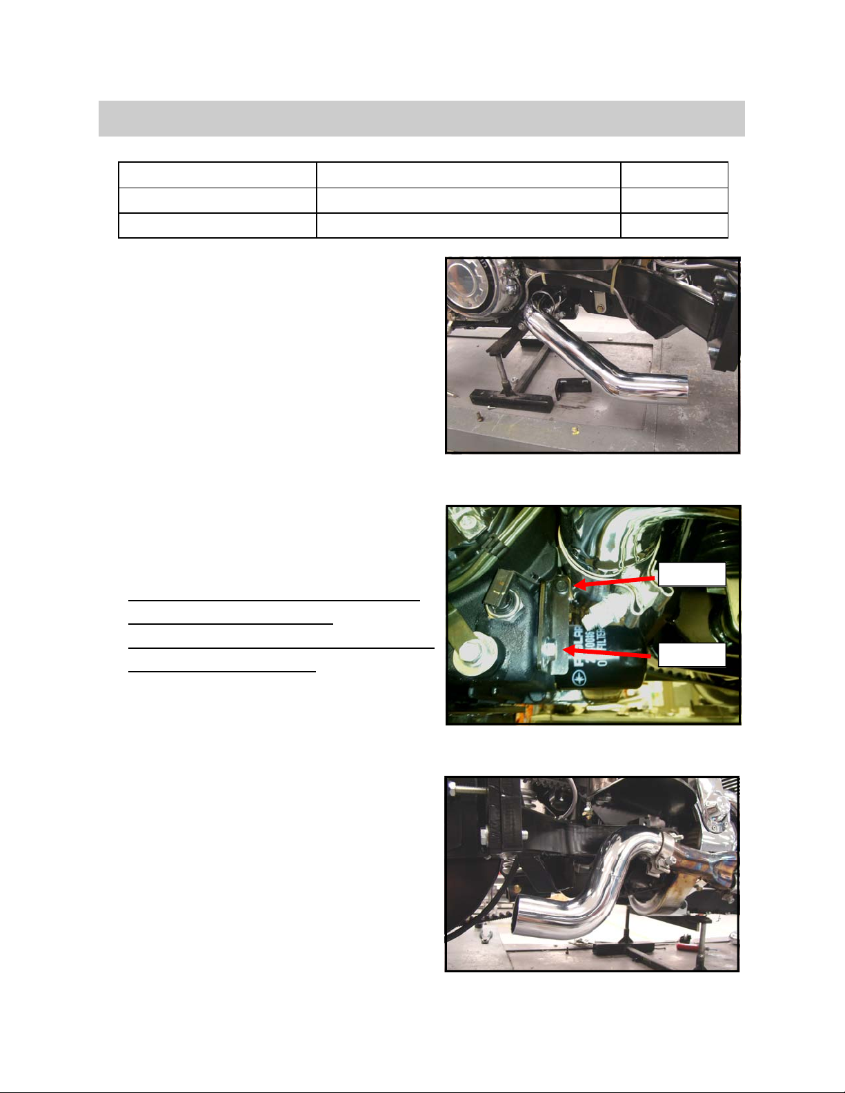
1. See Fig. 1. Install (1) left side exhaust pipe as
shown using (1) exhaust clamp.
• (1) Left Side Exhaust Pipe (S001166)
• (1) Exhaust Clamp (Take-Off)
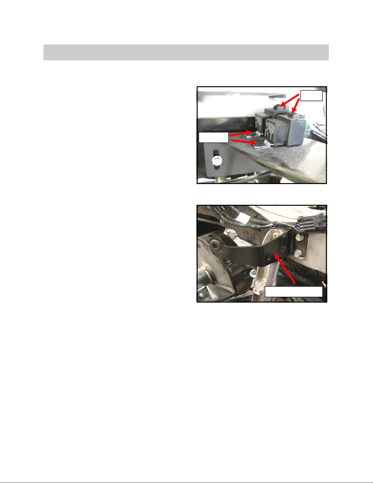
2. See Fig. 2. Install (1) polaris exhaust bracket to
transmission using (1) bolt (CB1906) in upper lo-
cation and (1) bolt (CB1928) with loctite 243.
Tighten using 4mm allen head socket and
15mm socket.
• (1) Polaris Exhaust Bracket (S001547)
• (1) Bolt (CB1906)
• (1) Bolt (CB1928)
3. Torque and mark upper exhaust bracket bolt
to 10 ft. lbs using 15mm socket.
4. Torque and mark lower exhaust bracket bolt to
35 ft. lbs using 15mm socket.
5. See Fig. 3. Install (1) right side exhaust pipe as
shown using (1) exhaust clamp.
• (1) Right Side Exhaust Pipe ( S001167)
• (1) Exhaust Clamp (S001412)
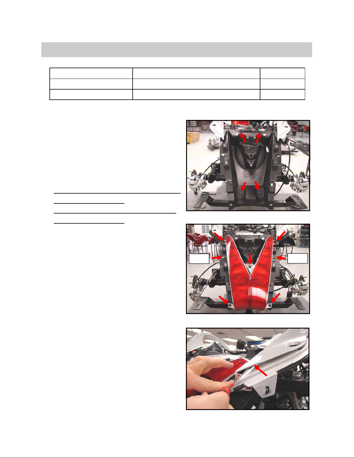
6. Re-install side covers with (1) push pin.
• (1) Push Pin (OEM take off)
• (1) Non Reverse Models Side Cover Set
(OEM)
OR
• (1) Reverse Models Side Cover Set
(Supplied with Reverse Kit) See modifica-
tion process on following page.
Fig. 1
Fig. 2
PART # PART DESCRIPTION TORQUE
CB1906 UPPER EXHAUST BRACKET BOLT (1) 10 FT LBS
CB1928 LOWER EXHAUST BRACKET BOLT (1) 35 FT LBS
Fig. 3
CB1906
CB1928

9
Side Cover Modification– Reverse Models
SIDE COVER MODIFICATION (REVERSE ONLY)
1. See Fig. 1. Using scribe lines on backside of side
covers, trim Left and Right side covers as shown
using air saw.
2. See Fig. 2. Install GT1800 weather seal to modi-
fied edges of side covers as shown.Use loctite
404 on inside edge of side covers to secure, being
careful not to get glue on outside edge of side
covers.
• Weather Seal (GT1800)
3. Install modified left and right side covers to trike.
Fig. 1
Fig. 2
Scribe Lines

10
Body Preparation, Installation, & Final Assembly
BODY PREPARATION
1. See Fig. 1. Drill out OEM latch assembly as
shown using 21/64” bit.
2. See Fig. 2. Install OEM latch assembly to OEM
latch bracket as shown using (2) take off bolts.
Tighten using 10mm socket.
• (1) Latch Assembly (OEM)
• (1) Latch Bracket (OEM)
• (2) Bolt (take off)
3. See Fig. 3. Install (1) latch cable to OEM latch as
shown using (1) SIR Clip and (1) Hair Clip.
• (1) Cable Door Release (S001504)
• (1) SIR Clip (provided with cable)
• (1) Hair Clip (S001510)
4. See Fig. 4. Install (1) latch cable to OEM latch
release mechanism as shown using (1) SIR Clip.
• (1) Latch Release Mechanism (OEM)
• (1) SIR Clip (S001531)
NOTE: Left side latch release mechanisms pull
from the bottom, right side latch release mecha-
nisms pull from the top.
Fig. 1
Fig. 2
Drill Out
Fig. 3
SIR Clip (provided)
Hair Clip
Fig. 4
SIR Clip (S001531)

11
Body Preparation, Installation, & Final Assembly
5. See Fig. 5. Acquire (1) Left Side Body. Install (2)
jam nuts to latch studs as shown.
• (1) Body (LS - S001437, RS - S001438)
• (2) Jam Nut (CN1904)
6. See Fig. 6. Install latch assembly to studs as
shown using (2) jam nuts. Tighten using 10mm
wrench.
• (2) Jam Nut (CN1904)
7. See Fig. 7. Secure latch release mechanism to
body as shown using masking tape.
8. See Fig. 8. Apply masking tape to trunk opening
as shown.
Fig. 5
Fig. 6
Fig. 7
Fig. 8

12
Body Preparation, Installation, & Final Assembly
DOOR PREPARATION
1. Acquire (1) Painted Left Side Door.
• (1) Door (LS - S001439, RS - S001438)
2. Acquire (1) section of weather seal and cut to 56”
using weather seal cutting tool.
• (1) Weather Seal 9.5’ (CW2535)
3. See Fig. 1. Mark V-notch cut in weather strip 18”
from one end.
NOTE: See Fig. 2. Ensure the vapor hole faces the
inside as shown.
4. Cut weather seal along indicated notch markings
using weather seal cutting tool.
5. Secure V-notched edges together using Loctite
404.
6. See Fig. 3. Install weather seal to backside of
door as shown starting at V-notched corner.
7. Apply weather seal to outer-most edge of door
seal surface around perimeter of door. Trim ends
to fit using weather seal cutting tool.
8. Secure the ends together using Loctite 404 on all
edges of the connection.
Fig. 3
Fig. 2
Fig. 1
Faces Inside
V-Notch
18”
Seam

13
Body Preparation, Installation, & Final Assembly
9. See Fig. 4. Install (1) left and (1) right hinge to
door with (1) concentric rod as shown using (6)
bolts. Tighten using 10mm socket.
• (1) Left Side Hinge (S001497)
• (1) Right Side Hinge (S001496)
• (1) Concentric Rod (S001409)
• (6) Bolt (CB1908)
NOTE: See Fig. 4. Pull the hinge assembly away
from the door when tightening as shown.
10. Mark the center of the concentric rod with a black
sharpie for alignment purposes in the body.
11. See Fig. 5. Install (1) striker latch to door as
shown using (2) nylock nuts. Tighten using 7mm
socket.
• (1) Striker Latch (OEM)
• (2) Nylock Nut (CN1900)
Fig. 5
Fig. 4
Tubing

14
Body Preparation, Installation, & Final Assembly
DOOR INSTALLATION / ADJUSTMENT
1. See Fig. 1. Install (1) prepped left side door to (1)
prepped left side body using (1) hinge pivot re-
tainer and (1) bolt. Leave a little loose for adjust-
ment purposes.
• (1) Hinge Pivot Retainer (S001411)
• (1) Bolt (CB1907)
2. Adjust door with the following adjustment options:
• Hinge - See Fig. 2. Adjusts door left and
right and rotationally as shown.
• Concentric Rod - See Fig. 3. Adjusts the
hinge side of the door’s depth ( in & out ).
• Latch Mechanism - See Fig. 3. Adjusts
the latch side of the door’s depth ( in &
out).
3. Make adjustments to the door until:
• A uniform gap is obtained around the pe-
rimeter of the door
• A flush surface is obtained between the
body and the door
• The bodyline of the door and body match
• The door does not contact the body upon
opening
• A consistent seal is obtained between the
mating surface of the door and body
• The latch engages and releases freely
NOTE: CW2086 washers can be installed to shim
up the striker if needed.
Fig. 1
Fig. 2
CB1907
Fig. 3
S001411
Hinge Side
Latch Side

15
Operation 50 - Body Preparation, Installation, & Final Assembly
4. See Fig. 4. Install (2) bump stops to body as
shown.
• (2) Bump Stop (ACE52728)
5. See Fig. 5. Install (1) U-Nut to body as indicated.
Mark hole and remove U-Nut.
• (1) U-Nut (CN3302)
6. Drill out hole for U-Nut using 5/32” bit. Re-install
u-nut to body.
7. See Fig. 6. Install GT1800 weather seal to seat
pan of body as shown. Use loctite 404 on inside
edge of body to secure, being careful not to get
glue on outside edge of body.
• Weather Seal (GT1800)
8. Repeat BODY PREPARATION, DOOR PREPA-
RATION, & DOOR INSTALLATION / ADJUST-
MENT sections for the right side body.
Fig. 4
Fig. 5
Bump Stop
Fig. 6

16
Body Preparation, Installation, & Final Assembly
BODY ALIGNMENT & INSTALLATION
1. Using another person to help, locate left side body
to trike. The body locates with the top grab han-
dle contour and rests on front and rear body
mounts.
2. See Fig. 1. Secure body to tail section as shown
using (1) screw. Tighten using Phillips screw-
driver.
• (1) Screw (CS4098)
3. See Fig. 2. Loosely fasten top of body to upper
body mount bracket using (1) Bolt, (1) Fender
Washer, and (1) Nylock Nut.
• (1) Bolt (CB1972)
• (1) Fender Washer (CW2109)
• (1) Nylock Nut (CN1908)
4. Repeat steps 1 through 3 for right side body.
5. See Fig. 3. Temporarily install (1) left and (1) right
lower valence as shown for alignment purposes
• (1) Left Side Lower Valence (S001511)
• (1) Right Side Lower Valence (S001511)
6. Adjust left and right side bodies until the following
clearances are achieved:
• 1/8” between front of body and side cover
• 1/8” between top of body and grab handle
• Tight between valence and body
• Tight between valence and tail light
7. Torque and mark upper body mount bolts (2)
to 22 ft. lbs using 13mm allen head socket and
13mm wrench.
Fig. 2
Fig. 3
Fig. 1
PART # PART DESCRIPTION TORQUE
CB1972 UPPER BODY MOUNT BOLTS (2) 22 FT LBS

17
Body Preparation, Installation, & Final Assembly
8. Drill hole for front body mount through front body
mount hole using 21/64” bit as shown
(Fig. 50-25).
9. Secure front of body to front body mount as
shown using (1) Bolt, (1) Flat Washer, and (1) Ny-
lock Nut. Tighten using 13mm Socket & 5mm
Allen Head Socket (Fig. 50-26).
• (1) Bolt (CB1929)
• (1) Fender Washer (CW2109)
• (1) Nylock Nut (CN1908)
10. Oversize (3) foot pad mounting holes using 21/64”
bit.
11. Drill indicated foot pad mounting hole through
front body mount using 21/64” bit (Fig. 50-26).
12. Install (1) LS foot pad to body using (3) flat wash-
ers and (4) nylock nuts. Tighten using 7/16”
wrench (Fig. 50-27).
• (1) LS Foot Pad (S001418)
• (3) 1/4 Flat Washer (CW2005)
• (3) 1/4 Nylock Nut (CN3042)
Fig. 50-25
Fig. 50-26
Fig. 50-27

18
Body Preparation, Installation, & Final Assembly
13. Drill pilot hole from bottom side of body to locate
rear body mount hole using 3/16” bit.
14. Finish drilling out the rear body mount hole from
topside of body using 21/64” bit.
15. See Fig. 4. Secure rear of body to rear body
mount using (1) bolt, (1) lock washer, and (1)
fender washer as shown. Tighten using 5mm al-
len head socket (Fig. 50-28).
• (1) Bolt (CB1624)
• (1) Lock Washer (CW2168)
• (1) Fender Washer (CW2109)
NOTE: Rear body mount is the front-most hole.
The rear-most hole is used for exhaust pipe
mounting.
16. See Fig. 5. Secure (1) latch release mechanism to
latch bracket as shown using (2) bolts. Tighten
using 10mm socket.
• (1) Latch Release Mechanism (OEM)
• (2) Bolts (CB1907)
NOTE: Ensure latch release mechanism is located
centrally in the keyhole.
Fig. 4
Fig. 5

19
Body Preparation, Installation, & Final Assembly
17. See Fig. 6. Drill hole for front body mount through
front body mount hole using 21/64” bit as shown.
18. See Fig. 7. Secure front of body to front body
mount as shown using (1) Bolt, (1) Flat Washer,
and (1) Nylock Nut. Tighten using 13mm Socket
& 5mm Allen Head Socket.
• (1) Bolt (CB1929)
• (1) Fender Washer (CW2109)
• (1) Nylock Nut (CN1908)
19. Oversize (4) foot pad mounting holes using 21/64”
bit.
20. Drill indicated foot pad mounting hole through
front body mount using 21/64” bit (Fig. 50-31).
21. See Fig. 8. Install (1) RS foot pad to body using
(3) flat washers and (4) nylock nuts. Tighten us-
ing 7/16” wrench.
• (1) RS Foot Pad (S001419)
• (4) 1/4 Flat Washer (CW2005)
• (4) 1/4 Nylock Nut (CN3042)
Fig. 6
Fig. 7
Fig. 8

20
Body Preparation, Installation, & Final Assembly
22. Drill pilot hole from bottom side of body to locate
rear body mount hole using 3/16” bit.
23. Finish drilling out the rear body mount hole from
topside of body using 21/64” bit.
24. See Fig. 9. Secure rear of body to rear body
mount using (1) bolt, (1) lock washer, and (1)
fender washer as shown. Tighten using 5mm al-
len head socket.
• (1) Bolt (CB1624)
• (1) Lock Washer (CW2168)
• (1) Fender Washer (CW2109)
NOTE: Rear body mount is the front-most hole.
The rear-most hole is used for exhaust pipe
mounting.
25. See Fig. 10. Secure (1) latch release mechanism
to latch bracket as shown using (2) bolts. Tighten
using 10mm socket.
• (1) Latch Release Mechanism (OEM)
• (2) Bolts (CB1907)
NOTE: Ensure latch release mechanism is located
centrally in the keyhole.
Fig. 9
Fig. 10
Table of contents