Introduction
Leica HM500/Ref. 10 715 697/Version B
User manual
In addition to instructions for use, this user man-
ual also provides important safety notes (see the
chapter entitled, "Safety notes").
Before commissioning the product, carefully read
through the user manual.
Product identification
The model and serial number of your product are shown on the
identification label. Enter this data in your User Manual and
always refer to it when you contact us or the service workshop
regarding any questions you may have.
Type: Serial No.:
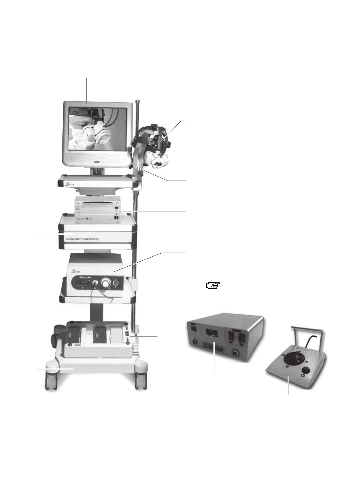
Product description
The Leica HM500 is a global first in the field of optical aids to
vision and has the following features:
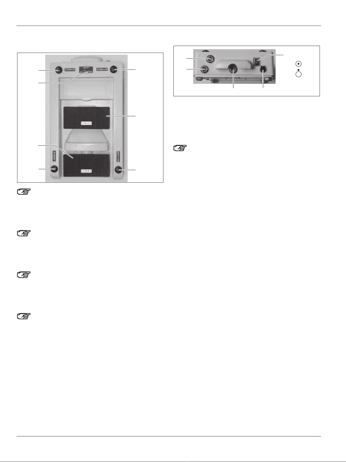
•Variable working distance (specimen – eye) which can be
varied between 300 and 700 mm with the aid of the autofocus
feature—in addition, the focus can be controlled manually by
the footswitch.
• Using the speed focus (holding down the manual focus
switch activates autofocus), you can focus quickly and pre-
cisely on the desired specimen, even in manual mode.
• For the standard eyepiece (20x), the magnification range is
between 2.9–7x. Within this range, each factor can be
selected using a foot switch.
Optional: Interchangeable eyepieces, eyepieces I (14x):
2.0x–4.8x or eyepiece II (26x): 3.75x–9x easily interchangeable
by the user.
• Automatic parallax compensation for focusing.
• Individual adaptation to eye characteristics (distance
between pupils) and correction of defective vision
(near/farsightedness, astigmatism) by means of an eyepiece
for eyeglass wearers.
• Improved depth perception and 3 effect due to an enlarged
stereoscopic parallax.
• The Leica HM500 does not need to be connected to the
power supply system to operate but runs on a battery
(footswitch) which gives a warning when the charge falls
below 10 %.
• Ergonomic headset with infinitely variable height adjustment
and adjustment of main movement axes.
• The ergonomic design of the Leica HM500 also enables the
user to view specimens to the side and below and above the
Leica HM500.
• To afford an unrestricted view downwards, the Leica HM500
can also be swung upwards without the headset needing to
be taken off.
• Integrated coaxial light for shadow-free illumination of the
operating field.
• Integrated autofocus camera in color for parallax-free pre-
sentation of the image information on a monitor, for example.
2