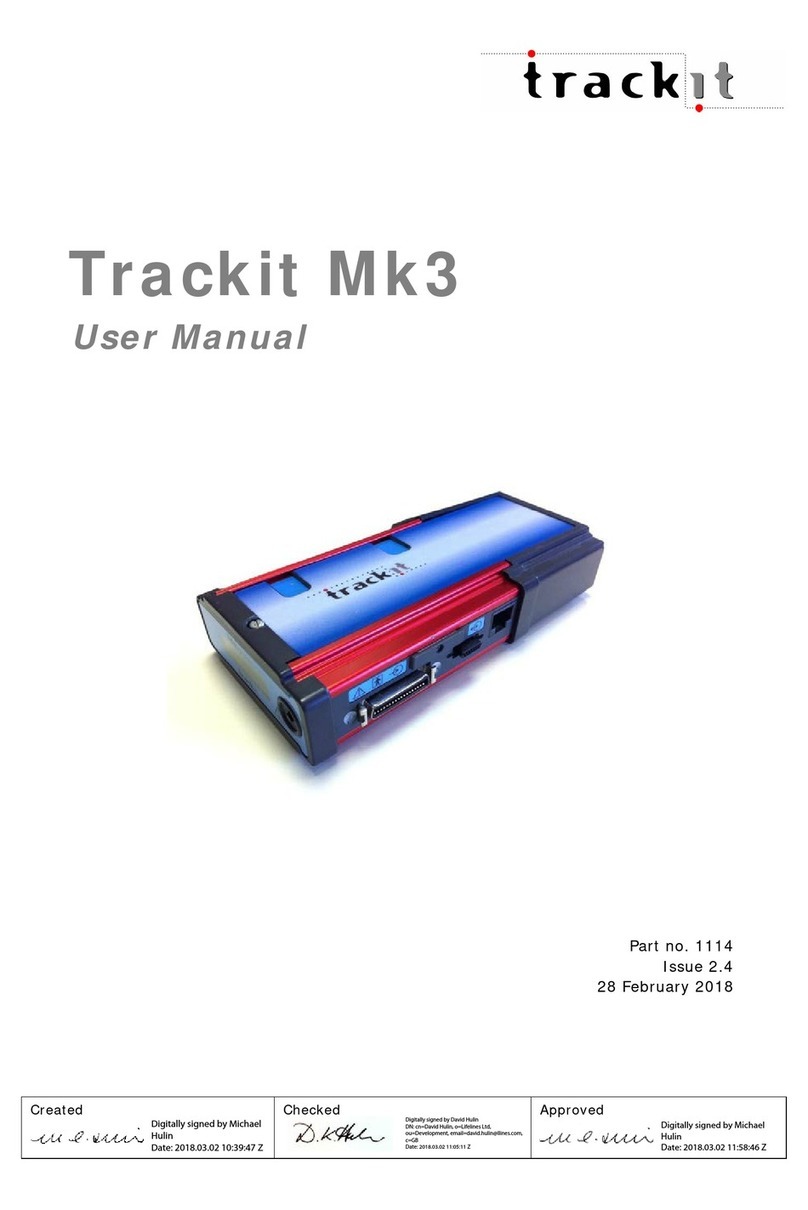
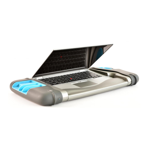
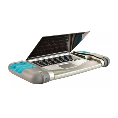
Lifelines trackit T4 User manual

USER MANUAL
®

Lifelines Ltd
1 Tannery House, Tannery Lane,
Woking, Surrey, GU23 7EF UK
Telephone +44 (0) 1483 224 245
www.lifelinesneuro.com
Incereb Ltd.
6 Charlemont Terrace, Crofton Road,
Dun Laoghaire, Dublin, A96 F8W5. Ireland.
Doc No: 51285-006
Part No: 51285-006
Issue: 2.1
CCN: CCN0152
Created
Checked
Approved
Digitally signed by Geoff
Salter
Date: 2021.12.07
18:38:44 Z
Digitally signed by David Hulin
DN: cn=David Hulin, o=Lifelines Ltd,
ou=Development,
Date: 2021.12.08 10:35:02 Z
Digitally signed by Geoff
Salter
Date: 2021.12.08 15:20:05
Z

USER
MANUAL
151285-006
Customer Responsibility
The Trackit T4 amplifier is reliable only when operated and maintained in accordance with the instructions
contained in this manual, accompanying labels, and inserts. A defective system should not be used. Parts that may
be broken or missing or those that are clearly worn or contaminated should be replaced immediately with new
original replacement parts that have been manufactured by or are available from Lifelines Neuro.
The owner of this system has the sole responsibility for any malfunction resulting from improper use or
maintenance, or repair done by anyone other than a qualified Lifelines Neuro representative and for any
malfunctions caused by any parts that have been damaged or modified by anyone other than a qualified Lifelines
Neuro representative.
The owner of this system has the sole responsibility for the connection of this product to other systems not
satisfying the electrical safety requirements class I, type BF, standards IEC 60601-1, IEC 60601-2-26, IEC 60601-1-11,
IEC 60601-1-2 for medical devices.
Customer Responsibility

USER
MANUAL
251285-006
Disclaimers & Warranties
Except as stated below, Lifelines Ltd makes no warranty of any kind with regard to this material, including, but
not limited to, the implied warranties of merchantability and fitness for a particular purpose. Lifelines shall not be
liable for errors contained herein or for incidental or consequential damages in connection with the furnishing,
performance or use of this material.
Lifelines shall warrant its products against all defects in material and workmanship for one year from the date of
delivery.
Misuse, accident, modification, unsuitable physical or operating environment, improper maintenance or damage
caused by a product for which Lifelines is not responsible will void the warranty.
Lifelines do not warrant uninterrupted or error-free operation of its products.
Lifelines or its authorised agents will repair or replace any products that prove to be defective during the warranty
period, provided that these products are used as prescribed in the operating instructions in the user’s and service
manuals.
No other party is authorised to make any warranty to assume liability for Lifelines products. Lifelines will not
recognise any other warranty, either implied or in writing. In addition, services performed by someone other than
Lifelines or its authorised agents or any technical modification or changes of products without Lifelines prior,
written consent may be cause for voiding this warranty.
Defective products or parts must be returned to Lifelines or its authorised agents, along with an explanation of the
failure. Shipping costs must be prepaid.
Lifelines Ltd. manufactures hardware and software to be used on or with standard PC-compatible computers
and operating software. Lifelines, however, assumes no responsibility for the use or reliability of its software or
hardware with equipment that is not furnished by third-party manufacturers accepted by Lifelines at the date of
purchase.
All warranties for third-party products used within the T4 system are the responsibility of the relevant
manufacturer. Please refer to the relevant documentation on each product for further details.
This document contains proprietary information that is protected by copyright. All rights are reserved. No part of
this document may be photocopied, reproduced in any other form or translated into another language without the
prior written consent of Lifelines.
Trademarks
Microsoft, Windows and Windows NT are registered trademarks of the Microsoft Corporation. All other trademarks
and product names are the property of their relevant owners.
Safety
Disclaimers & Warranties

USER
MANUAL
351285-006
Responsibility of manufacturer
The manufacturer and distributor consider themselves responsible for the equipment’s safety, reliability and
performance only if:
yany peripheral equipment to be used with the T4 system is supplied by third-party providers recommended by
the manufacturer;
yassembly operations, extensions, readjustments, modifications, or repairs are carried out by persons authorised
by the manufacturer;
ythe electrical installation of the relevant room complies with the appropriate requirements;
ythe equipment is used by a health-care professional and in accordance with the instructions for use.
NOTE: the manufacturer has a policy of continual product improvement; hence the equipment specifications
are subject to change without notice.
Check with Lifelines or your distributor if a software update is available.
NOTE: Medical electrical equipment needs special precautions regarding EMC and needs to be installed and
put into service according to the EMC information provided in the Appendix.
Software and Virus Protection
Lifelines takes all reasonable steps to ensure that its software is virus-free. In line with modern computing practice,
it is advisable that continual protection against viruses, trojans, malware, adware etc. is provided on the PC
used for installation and the surrounding systems. Please note the following recommendations which should be
supported by your internal IT/Computing department procedures and practices:
yVirus protection software should be installed on every computer at risk of infection. This software should have a
resident (online) shield and provide email scanning if appropriate.
yVirus scanning should be set to manual mode or automatic if desired but at a time when the system is not
being used.
yAll programs offering auto-update features, including Windows, should be set to manual or automatic if desired
but at a time when the system is not being used.
yAdopt formal departmental or organisational procedures to ensure the integrity and safe operation of the
medical equipment and supporting systems.
Disclaimers & Warranties

USER
MANUAL
451285-006
Contents
Disclaimers & Warranties.................................................................................................................................................2
1 Overview and Technical Description............................................................................................................... 6
1.1 General description..................................................................................................................................................................................... 6
1.2 Warnings and Cautions.............................................................................................................................................................................7
1.3 Explanation of symbols ............................................................................................................................................................................9
1.4 The Amplifier and its parts ..................................................................................................................................................................10
1.5 Specifications and safety........................................................................................................................................................................11
1.6 Description of the components........................................................................................................................................................12
1.7 Replaceable parts....................................................................................................................................................................................... 14
2 Installation and Maintenance .............................................................................................................................15
2.1 Checks for completeness and integrity .................................................................................................................................... 15
2.2 Environmental parameters for operation................................................................................................................................. 15
2.3 Power supply connections.................................................................................................................................................................. 16
2.4 Battery Operation Time.......................................................................................................................................................................... 16
2.5 Use in the home environment............................................................................................................................................................17
2.6 Use with other equipment ....................................................................................................................................................................17
2.7 Interference..................................................................................................................................................................................................... 18
2.8 Maintenance and cleaning.................................................................................................................................................................. 18
2.9 Disposal of equipment............................................................................................................................................................................ 18
3 Connections and usage .........................................................................................................................................19
3.1 Overview............................................................................................................................................................................................................ 19
3.2 Laptop installation and operation................................................................................................................................................. 20
3.3 Connecting the T4 System................................................................................................................................................................... 21
3.4 Starting the system .................................................................................................................................................................................. 24
3.5 Shutdown of the system.......................................................................................................................................................................25
3.6 Battery replacement and charging.............................................................................................................................................. 26
3.7 Micro-SD Card..............................................................................................................................................................................................27
4 Trackit Software - overview ................................................................................................................................29
Version History ....................................................................................................................................................................47
USER
MANUAL
551285-006
Illustrations
Figure 1: Connecting the T4 Amplifier – Clinical Use..................................................................................................................19
Figure 2: Connecting the T4 Amplifier - Home Use....................................................................................................................20
Figure 3: T4 amplifiers and PCUs .............................................................................................................................................................22
Figure 4: T4 PCU 32+3.......................................................................................................................................................................................23
Figure 5 Connecting the T4 Amplifier (back face).......................................................................................................................24
Figure 6: T4 Amplifier display indicators.............................................................................................................................................25
Figure 7: Battery replacement 1 .................................................................................................................................................................26
Figure 8 Battery replacement 2.................................................................................................................................................................26
Figure 9 Photic Stimulation (using Trackit Plus software)....................................................................................................33
Figure 10 Photic Stimulation control window .................................................................................................................................33
Figure 11: Photic trigger signal definition............................................................................................................................................34
Figure 12: Bluetooth pairing ..........................................................................................................................................................................36
Figure 13: WiFi setup...........................................................................................................................................................................................37
Figure 14: Unsecure network error message .................................................................................................................................. 37
Figure 15: Bluetooth connection quality monitor. ........................................................................................................................38
Appendices
Appendix 1: Trackit T4 Amplifier Specifications .......................................................................................................30
Appendix 2: Photic Stimulation ......................................................................................................................................... 33
Appendix 3: Additional Events Information................................................................................................................ 35
Appendix 4: Wireless............................................................................................................................................................... 36
Appendix 5: Troubleshooting Guide ............................................................................................................................... 42
Appendix 6: Manufacturer’s Declaration.....................................................................................................................43

USER
MANUAL
651285-006
1 Overview and Technical Description
1.1 General description
Indications for use
The T4 EEG Amplifier is intended to be used as a front-end amplifier to acquire, store and transmit
electrophysiological signals (wireless or cabled).
CAUTION: Federal (USA) law restricts this device to sale by or on the order of a physician.
General description
The Trackit T4 EEG Amplifier is a multi-channel electroencephalograph designed for use in routine EEG and lab
monitoring applications and due to its small size, can be used in ambulatory applications. In this situation, the
EEG electrodes are fitted to the patient by a trained clinician prior to the patient being sent home. No subsequent
intervention is required by the patient. Upon completion of the recording, the data which is stored on a memory
card is reviewed by a clinician using review and analysis software on a PC.
It is a compact USB amplifier which provides 32 channels (or 68 channels with internal expansion option) with
built-in calibration and electrode impedance measurement. Also provided is a Nonin pulse oximeter interface, a
Patient Event input and an Aux DC input. Optional wireless communication is available (Bluetooth and WLAN WiFi).
There are two variants of the Trackit T4 EEG Amplifier:
yTrackit T4-32 providing 24 referential + 8 poly channels.
yTrackit T4-68 providing 64 referential + 4 poly channels.
Plug-on Patient Connection Units (PCUs) provide 32 channel touchproof inputs (model T4-PCU 24+8) or 68
channels (model T4-PCU 64+4).
Also available is model T4-PCU 32+3 Patient Connection Unit which provides a dedicated Electrocap D-type
connector plus an additional 10 channels of non-overlapping EEG and 3 poly bipolar channels.
The Amplifier is intended to be connected to a USB port on a PC which is powered from a medically approved
power supply. In addition it can be battery powered in ambulatory applications.
This equipment is intended only as an adjunct device in patient assessment; it must be used in conjunction with
other methods of patient diagnosis. The equipment does not sustain or support life.
Intended User
The intended user of the equipment is a healthcare professional who has the training and knowledge to undertake
EEG examinations and is familiar with EEG equipment and practice.
Overview and Technical Description

USER
MANUAL
751285-006
1.2 Warnings and Cautions
Warning sign indicates a situation or
procedures that may be dangerous for
the patient and/or user.
Caution sign indicates a situation or
procedures that may cause equipment
damage or its improper usage.
Do not use the T4 EEG Amplifier in an MRI environment, in an oxygen rich environment or during
defibrillation.
This equipment is intended to be used by a healthcare professional and in accordance with these
instructions for use which must be read in their entirety before the device is used.
This equipment in intended only as an adjunct device in patient assessment; it must be used
in conjunction with other methods of patient diagnosis. This equipment is not be used for the
determination of brain death.
Only use the laptop and the medical-grade power supply as supplied or authorised by Lifelines. Do
not use the standard laptop power supply
The Amplifier must only be used with the USB Power Bank supplied or authorised by Lifelines.
To avoid the risk of electric shock, this equipment must only be connected to a supply mains with
protective earth.
Lifelines does not supply EEG electrodes. The unit accepts standard 1.5 mm touchproof electrodes
using DIN 42802-style connectors. To ensure patient safety, the electrodes used must be approved
to the Medical Device Directive 93/42/EEC in Europe or FDA cleared for use in USA.
The conductive part of electrodes and their connectors, including the Neutral electrode, should not
contact other conductive parts including earth.
Do not plug the USB connector into any device other than the PC supplied or authorised by Lifelines.
Do not connect any other equipment to the PC.
Do not touch simultaneously any accessible USB or other contacts on the PC and the patient.
Strangulation hazard due to long cables. As with all medical equipment, carefully route patient
cabling to reduce the possibility of patient entanglement or strangulation.
Ensure that carrying bag and straps are worn over clothing to prevent any possibility of skin irritation.
Overview and Technical Description

USER
MANUAL
851285-006
The function or safety of the equipment could be impaired if it has been subjected to unfavourable
conditions in storage or in transit. If at any time function or safety is thought to be impaired, the
instrument should be taken out of operation and secured against unintended use.
Do not open or modify the equipment without the authorization of the manufacturer.
Medical electrical equipment needs special precautions regarding EMC and needs to be installed
and put into service according to the EMC information provided in the Appendix.
Portable RF communications equipment (including peripherals such as antenna cables and external
antennas) should be used no closer than 30 cm (12 inches) to any part of the Trackit T4, including
cables specified by Lifelines Ltd. Otherwise, degradation of the performance of this equipment could
result.
When in close proximity to the T4 Amplifier, do not use mobile phones, transmitters, power
transformers, motors, or other equipment that generates magnetic fields. Refer to the Appendix for
more information.
Only use approved sensors as specified by Lifelines.
The Amplifier must only be used with the USB cable provided with the unit.
Do not allow any liquid to enter the case of the instrument or connector. Do not use acetone on any
of the instruments.
Federal (USA) law restricts this device to sale by or on the order of a physician.
CONTRAINDICATIONS: There are no known contraindications to the use of this equipment.
Overview and Technical Description

USER
MANUAL
951285-006
1.3 Explanation of symbols
Symbol Meaning
Type BF applied part
Input/output connection
Special recycling required*
Consult warnings in User Manual
Remote event pushbutton
On/O and patient event switch
Manufacturer
Internal battery hazard
- refer to section 1.7
Symbol Meaning
Follow operating instructions
Input connection
Bluetooth
WLAN WiFi
Nonin Xpod Pulse Oximeter
Memory card read/write
European Representative
* Special recycling required, do not dispose of in landfill. When this equipment has reached the end of its useful life, it must be disposed of in
an environmentally-friendly way. Waste electrical and electronic equipment (WEEE) requires special procedures for recycling or disposal.
This includes batteries, printed circuit boards, electronic components, wiring and other elements of electronic devices. Follow all of your
respective local laws and regulations for the proper disposal of such equipment. Contact your local distributor for information concerning this.
Storage and transport symbols
Symbol Meaning Symbol Meaning Symbol Meaning
Temperature limits Fragile Keep dry
Relative humidity
limits
Atmospheric
pressure limits IP22 International
protection code*
*Protected against ingress of solid object 12.5 mm diameter.
*Protected against access to hazardous parts with finger.
*Protected against ingress of water dripping (15° tilted)
Overview and Technical Description

USER
MANUAL
1051285-006
1.4 The Amplifier and its parts
The T4 EEG Amplifier is a multi-channel electroencephalograph designed for use in routine EEG and lab
monitoring applications.
It is a compact USB amplifier which provides 32 channels (or 68 channels with internal expansion option) with
built-in calibration and electrode impedance measurement. A Nonin XPOD interface is provided, a Patient Event
input and an Aux DC input. Optional wireless communication is available (Bluetooth and WLAN WiFi).
The Amplifier is intended to be connected to a specific PC or laptop and a medical grade power supply. Refer to
section 3.1 for details.
The PC or laptop must only be powered using the medical-grade mains power supply, as supplied
or authorised by Lifelines.
The T4 EEG Amplifier comprises the following components:
Component Part Number
T4-32 Amplifier 1505
T4-68 Amplifier 1501
T4-PCU 24+8 1552
T4-PCU 64+4 1553
T4-PCU 32+3 1556
USB Power Bank battery 10Ah 1581
USB Power Bank battery 20Ah 1582
Battery cable 1561
T4 bag and straps 1562
Patient event switch 1353
Xpod Pulse Oximeter Nonin 1327
Trackit tool 1115
Amplifier USB cable 1277
Medical grade power supply 1390
Mains cable, UK 1066
Trackit software CD, standard 1009
Part numbers may be preceded by ‘L14’ on labelling or packaging.
Overview and Technical Description

USER
MANUAL
1151285-006
1.5 Specifications and safety
Refer to Appendix 1 for specifications.
The amplifier has been certified and complies with the following standards:
Standard Description
IEC 60601-1 and
IEC 60601-2-26
Standard for medical electrical equipment, general requirements and particular
requirements for EEG systems.
IEC 60601-1-11 Collateral standard for medical electrical equipment used in the home
healthcare environment.
IEC 60601-1-6 Collateral standard for usability.
ANSI/AAMI ES 60601-1 AAMI Deviations from IEC 60601-1 (USA).
CAN/CSA 22.2 No 601.1 M90 Canadian standard for medical electrical equipment, general requirements.
IEC 60601-1-2 Standard for medical electrical equipment, EMC requirements, calling:
*CISPR11 Conducted Emissions, Group 1, Class B
CISPR11 Radiated Emissions, Group 1, Class B
IEC61000-4-2 Electrostatic Discharges
IEC61000-4-3 Immunity - Radiated RF Field
*IEC61000-4-4 Immunity - Transients Bursts
*IEC61000-4-5 Immunity – Surges
IEC61000-4-6 Immunity – Conducted
IEC61000-4-8 Immunity – Power frequency fields
*IEC61000-4-11 Immunity – Voltage dips, interruptions
*IEC61000-3-2 Harmonic Emissions
*IEC61000-3-3 Voltage Fluctuations/flicker
*Note: Compliance is provided by the PC.
Overview and Technical Description

USER
MANUAL
1251285-006
Classification of system
Classification Clinical use Home use
Degree of protection
against electrical shock
Internally powered; or it can be
connected to a PC which is powered
by a medical grade Class I power
supply.
Type BF applied parts.
Trackit T4 Amplifier:
Internally powered.
Type BF applied parts.
If a PC is supplied, the PC has no
electrical connection to the Amplifier
and has no applied parts.
Degree of protection
against harmful ingress of
water
Ordinary (no protection) or IP22
(Amplifier in bag)
IP22 (Amplifier in bag)
Mode of operation Continuous operation Continuous operation
Suitability for use in an
oxygen rich environment
Not suitable Not suitable
1.6 Description of the components
The T4 Amplifier
The T4 USB amplifier provides 32 channels (or 68 channels with internal expansion option) with built-in calibration
and electrode impedance measurement. A Nonin XPOD interface is provided, a Patient Event input and an Aux
DC input. The Amplifier has built in type-BF patient isolation and has a USB interface to the PC. Optional wireless
communication is available (Bluetooth and WLAN WiFi).
The Patient Connection Unit (PCU) connects the standard 1.5mm touch¬proof EEG recording electrodes attached
to the patient to the T4 unit. It is available either as a T4-PCU 24+8 (32 channel) unit, a T4-PCU32+3 (ECAP + 10
channels), or a T4 PCU 64+4 (68 channel). The PCU is plugged into the front of the unit and retained with two
screws operated by the supplied special tool.
Applied parts, type BF
EEG Electrodes
The amplifier connects to standard 1.5mm touchproof EEG recording electrodes arranged in a standard 10-20
pattern, attached to the patient’s head.
Lifelines does not supply EEG electrodes. The Amplifier accepts standard 1.5 mm touchproof
electrodes using DIN 42802-style connectors. To ensure patient safety, the electrodes used must be
approved to the Medical Device Directive 93/42/EEC in Europe or to the relevant local standards
outside Europe.
The conductive part of electrodes and their connectors, including the Neutral electrode, should not
contact other conductive parts including earth.
Overview and Technical Description

USER
MANUAL
1351285-006
Oximeter Sensor
The amplifier is approved for use with a Nonin 8000AA sensor which attaches to the patient’s finger.
Patient Event pushbutton
The Patient Event Pushbutton is used by the patient to mark the instance of a significant event.
Aux DC Input
The amplifier is approved for use with a SleepSense body position sensor, type 1575, for hospital and clinic use. Not
for home use.
Only use approved sensors as specified by Lifelines.
USB Cable for connection to PC
For non-ambulatory applications the Amplifier can be plugged directly into a USB port on the PC.
The Amplifier must only be used with the USB cable provided with the unit.
USB Power Bank battery pack for ambulatory applications
The Amplifier plugs directly into the USB port on the Power Bank.
The Amplifier must only be used with the USB Power Bank supplied or authorised by Lifelines.
Micro-SD memory card
The micro-SD card is used to store the EEG data recorded by T4. Storage cards of varying capacity are available in
the micro-SD format.
Bags and straps for ambulatory applications
The Bag houses the Amplifier and battery.
Medical grade AC/DC mains power supply module for Laptop PC
Where EEG studies are conducted within the patient environment the leakage current must be controlled. The
laptop PC mains power supply must be a special medical-grade type with appropriate safety standards, supplied
or authorised by Lifelines.
Only use the laptop and the medical-grade power supply as supplied or authorised by Lifelines.
Do not use the standard laptop power supply
Overview and Technical Description

USER
MANUAL
1451285-006
The Setup and Recording Software
The Trackit setup software runs under Microsoft Windows 2000 (with SP2), Windows XP, Windows Vista, Windows
7, 8 or 10 on the host PC and is used to setup and review the T4 Amplifier and to record on to the PC.
Functions of the software:
yDownload the recording template. This includes which electrodes are used and the recording montage.
yPerform a calibration check of the Amplifier.
yPerform an Impedance check on the electrode inputs.
yPerform an EEG recording.
yView on-going EEG traces.
Refer to the Trackit Plus software manual for more details.
1.7 Replaceable parts
Lifelines Ltd. will make available on request circuit diagrams, component part lists, descriptions, calibration
instructions, or other information that will assist service personnel to repair those parts that are designated by
Lifelines Ltd. as repairable by service personnel.
Internal battery replacement – service personnel only
The T4 amplifier contains a replaceable lithium ion rechargeable coin cell, type LIR2450.
Battery replacement by inadequately trained personnel could result in a hazard. It must be replaced
only with the correct type and it must be installed correctly with +ve uppermost.
1. Remove the PCU.
2. Remove the four screws from the underside of the T4 amplifier as well as the two screws from the front (PCU
end) moulding and the two screws from the connector end moulding. Remove the bottom of the case.
3. Unclip the wraparound screen to expose the battery beneath.
4. Using a NON-CONDUCTIVE tool (for example, a spudger, plastic card or pen lid) place the tool under the coin
cell battery and, without exerting any stress on the holder itself, gently prise out the battery at the negative
terminal end. The battery should release from the battery holder.
5. Remove the battery from the battery holder.
6. Locate the replacement battery, positive side up, against the POSITIVE terminal of the battery holder.
7. Gently push the battery, at the negative terminal end, into the battery holder. The battery will click into place.
NOTE: The positive terminal of the battery holder has a metal tab.
The battery must be located UNDER the tab. Take care not to bend
the tabs when inserting the battery. The image (right) shows the
metal tab.
8. Gently push the battery, at the negative terminal end, into the
battery holder. The battery will click into place.
9. Re-clip the wraparound screen and reassemble the case.
Battery safety instructions
Do not attempt to open, puncture, disassemble or modify the battery in any way.
Do not subject the battery to sudden shock or heat.
Do not dispose of battery in fire.
Overview and Technical Description

USER
MANUAL
1551285-006
Installation and Maintenance
2 Installation and Maintenance
The following section must be read and understood before the equipment is switched ON.
Medical electrical equipment needs special precautions regarding EMC and needs to be installed
and put into service according to the EMC information provided in the Appendix.
The function or safety of the equipment could be impaired if it has been subjected to unfavourable conditions in
storage or in transit. If at any time function or safety is thought to be impaired, the instrument should be taken out
of operation and secured against unintended use.
The manufacturer should be contacted (details on page ii) for assistance, if needed, in setting up, using or
maintaining the equipment; or to report unexpected operation or events.
The assembly of the system and any modifications during its service life require evaluation to the requirements of
IEC 60601-1.
2.1 Checks for completeness and integrity
1. Remove the equipment from the packaging case(s).
2. Use the parts list to check that all ordered items have been received.
3. Check for signs of damage that may have occurred during transit or storage. If any damage is found, do not use
the instrument; contact your distributor.
2.2 Environmental parameters for operation
The operational and storage/transportation environmental conditions are as follows:
Operational: Storage and transport:
Temperature +5°C to +40°C
(+41°F to +104°F)
Temperature -25°C to +70°C
(-13°F to +158°F)
Relative humidity 15% to 93%
non-condensing
Relative humidity Up to 93% non-
condensing at +70°C
(158°F)
Atmospheric pressure 700 hPa to 1060 hPa Atmospheric pressure 500 hPa to 1060 hPa

USER
MANUAL
1651285-006
2.3 Power supply connections
Trackit T4 Amplifier
Power requirements Standard USB port (5V)
Power consumption Maximum power from USB port: 2.5W.
The Amplifier must only be used with the USB cable provided with the unit.
Medical grade AC mains power supply module for Laptop PC
Where EEG studies are conducted within the patient environment the leakage current must be controlled. The
mains power supply must be a special medical-grade type with appropriate safety standards, as supplied or
authorised by Lifelines.
Medical grade AC mains power supply module for Laptop PC
Mains Power input: 100–240 Vac, 47–63 Hz, 1.4 A @ 115 Vac, 0.7 A @ 230 Vac.
Output: 20 Vdc, 5.25 A.
The laptop must only be connected to the medical-grade laptop power supply supplied or
authorised by Lifelines. Do not use a standard laptop power supply.
Only use the laptop supplied or authorised by Lifelines.
To avoid the risk of electric shock, this equipment must only be connected to a supply mains with
protective earth.
2.4 Battery Operation Time
USB Powerbank
When fully charged the battery pack will typically power the unit for 36 hours depending on the number of
channels, sample rate and wireless usage.
The typical service life is 2 years.
Internal Li-Ion backup battery
The internal backup battery will enable the unit to continue operating for a short period of time (15 mins approx.)
to allow the main battery pack to be replaced. It is recharged automatically, whenever the main battery pack is
connected, with acquire o. The state of charge is displayed, as described in section 3.4, whenever the unit is
internally powered from the backup battery. To charge manually, operate the pushbutton several times to activate the
backlight and if the reading drops below approximately 70%, charge the battery for about 60 minutes by connecting
the main battery pack or connecting to a USB port.
The typical service life is 500 charge-discharge cycles.
Installation and Maintenance

USER
MANUAL
1751285-006
2.5 Use in the home environment
Where the equipment is intended to be used in the home, the unit should be operated in its bag where it is
protected against ingress of solid objects and water to a degree of IP22.
The laptop PC is optional in the home environment and may be used for video recordings. There is no cable
connection between the PC and the T4 Amplifier unit, as all communication is accomplished wirelessly.
Keep the equipment away from sources of heat.
Do not use mobile phones.
Do not allow pets or children to interfere with the equipment or sensor cables.
When the equipment is operated with or without its Bluetooth or WiFi on, other devices in the vicinity should be
moved away or turned o to reduce the likelihood of interference to the equipment or by the equipment.
The T4 may have internal radios fitted. These are approved industry-standard Bluetooth and WiFi types which
present minimal risk of reciprocal interference with other equipment.
2.6 Use with other equipment
Defibrillators and HF surgical equipment
The equipment is not defibrillator proof and should not be used in situations where a defibrillator is likely to be used.
The equipment should not be used with, or in the presence of, high frequency surgical equipment.
Other patient-connected equipment
When used simultaneously with other patient-connected equipment, for example a cardiac pacemaker or other
electrical stimulator, it is unlikely that a safety hazard will arise. However always consult the documentation
supplied with the other patient-connected equipment to ensure that all hazards, warnings and cautions are
considered before the equipment is used together.
Leakage current
This system is designed to comply with IEC 60601-1, the international standard for medical electronic equipment, which
specifies the permissible levels of leakage current. A potential hazard exists in the summation of leakage currents
caused by connecting several pieces of equipment together. Because this system can be used in conjunction with
standard electronic devices, the total leakage current should be tested whenever the system is modified.
There should be no electrical connections between the system equipment, which is powered via a medical grade
power supply, and any other equipment powered from another mains supply.
Installation and Maintenance

USER
MANUAL
1851285-006
2.7 Interference
The T4 will continue to operate in the presence of radio frequency magnetic fields (RF) and the eects of electrostatic
discharges (ESD) and other interference, in accordance with the requirements of EN60601-1-2. However, the T4 amplifier
records signals of very low amplitude, and these signals themselves are not immune to the eects of RF, ESD and low-
frequency magnetic field interference. Such interference may cause signal artefacts.
The T4 may have internal radios fitted. These are approved industry-standard Bluetooth and WiFi types which present
minimal risk of reciprocal interference with other equipment.
However, when the equipment is operated with or without its Bluetooth or WiFi on, other devices in the vicinity should be
moved away or turned o to reduce the likelihood of interference to the equipment or by the equipment
Portable RF communications equipment (including peripherals such as antenna cables and external antennas)
should be used no closer than 30 cm (12 inches) to any part of the Trackit T4, including cables specified by
Lifelines Ltd. Otherwise, degradation of the performance of this equipment could result.
When in close proximity to the T4 Amplifier, do not use mobile phones, transmitters, power transformers, motors,
or other equipment that generates magnetic fields. Refer to the Appendix for more information.
Medical electrical equipment needs special precautions regarding EMC and needs to be installed and put into
service according to the EMC information provided in the Appendix.
2.8 Maintenance and cleaning
The T4 Amplifier and its accessories require no routine testing, calibration or maintenance procedures apart from
occasional cleaning and checking for wear and damage to all parts including the accessories.
No servicing or maintenance of the equipment should take place while in use with a patient, except for
replacement of the external battery.
Cleaning and disinfection
Prior to each re-use of the system, all the outer surfaces of the T4 Amplifier, bag and power pack may be cleaned,
as required, with a cloth moistened with a mild detergent solution.
Disinfection of the equipment can be carried out by the use of QAC-based disinfectants. Wipes are recommended
in order to prevent the ingress of any liquid into the equipment. Suitable products include Mikrozid Sensitive Wipes
(Schülke & Mayr GmbH), Microbac forte (Paul Hartmann AG), Distel Wipes (Tristel Ltd.), Micro-Kill Disinfectant
Wipes, Sani-Cloth HB Germicidal Wipes (Medline).
For cleaning instructions for the laptop refer to the manufacturer’s documentation.
Do not allow any liquid to enter the case of the instrument or connector. Do not use acetone on any of the
instruments.
2.9 Disposal of equipment
When the device and its parts and accessories has reached the end of its operating life, it should be disposed of in
accordance with local waste regulation authority that is typically within the local government oice.
Dispose of used battery packs promptly and keep away from children.
Do not dispose of battery packs into fire or by incineration.
Installation and Maintenance
Other manuals for trackit T4
1
Table of contents
Other Lifelines Medical Equipment manuals

Lifelines
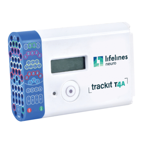
Lifelines trackit T4 User manual

Lifelines
Lifelines Trackit M User manual

Lifelines
Lifelines neuro R40 User manual

Lifelines
Lifelines trackit T4A User manual

Lifelines
Lifelines trackit M EEG SYSTEM User manual

Lifelines
Lifelines trackit Mk3 User manual

Lifelines
Lifelines trackit T4A User manual

Lifelines
Lifelines neuro R40 User manual

Lifelines
Lifelines trackit Mk3 User manual

Lifelines
Lifelines Photic User manual