Leica PaveSmart 3D User manual

PaveSmart 3D UM 2Introduction
Introduction
Purchase Congratulations on your purchase of the Leica PaveSmart 3D Machine Control System. Leica
PaveSmart 3D is the world's leading machine control system for increasing productivity in
paving and milling applications.
This manual contains important safety directions as well as instructions for setting up the
system and operating it. Refer to "6 Safety Directions" for further information.
Read carefully through the User Manual before you switch on the product.
To ensure safety when using the system, please observe the directions and instructions
contained in the User Manual and Safety Handbook issued by the:
• Machine manufacturer,
• Controller manufacturer and
• Sensor manufacturer.
Product
identification
The type and serial number of your product are indicated on the label on the base of the
product.
Enter the model and serial number in your manual and always refer to this information when
you contact your agency or Leica Geosystems authorised service workshop.
Type: MPC1310 Machine Computer Serial number: _______________
Type: MSS1200 Dual-Axis Slope Sensor Serial number: _______________
Type: TCPS27S/29S Ruggedised Radio Modem Serial number(s):_______________
Type: MCR-900 Ruggedised Radio Modem
(900MHz, North America only)
Serial number: _______________

Introduction PaveSmart 3D UM 3
Symbols The symbols used in this manual have the following meanings:
Trademarks • Windows is a registered trademark of Microsoft Corporation
• GOMACO is a registered trademark of Gomaco Corporation, Ida Grove, IA, USA
• Wirtgen is a registered trademark of Wirtgen Group, Windhagen, Germany
• MOBA is a registered trademark of MOBA Mobile Automation AG, Germany
• Vögele is a registered trademark of Wirtgen Group, Windhagen, Germany
• G&Z is a registered trademark of Guntert & Zimmerman Inc., Ripon, CA, USA
• PowerCurbers is a registered trademark of PowerCurbers Inc., Salisbury, NC, USA
• PowerPavers is a registered trademark of PowerPavers Inc., Cedar Falls, IA, USA
All other trademarks are the property of their respective owners.
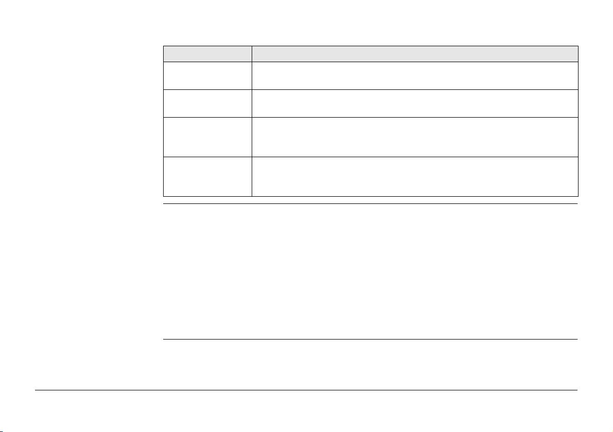
Type Description
Danger Indicates an imminently hazardous situation which, if not avoided, will
result in death or serious injury.
Warning Indicates a potentially hazardous situation or an unintended use which,
if not avoided, could result in death or serious injury.
Caution Indicates a potentially hazardous situation or an unintended use which,
if not avoided, may result in minor or moderate injury and/or appreci-
able material, financial and environmental damage.
Important paragraphs which must be adhered to in practice as they
enable the product to be used in a technically correct and efficient
manner.

PaveSmart 3D UM 4Table of Contents
Table of Contents
In this manual Chapter Page
1 How to use this Manual 6
2 Getting Started 12
2.1 Preparing the Leica PaveSmart 3D System 12
2.2 Operating the MPC1310 Machine Computer 14
2.3 Rules for Defining Projects 35
2.4 Preparing the Leica PaveSmart 3D Software for the Current Project 37
2.5 Selecting Design Reference Lines 42
2.6 Adjusting Working Offsets during Production 49
2.7 Continue Working Depending on the Current Machine Position 50
2.8 Positioning the Machine for Production 57
2.9 Taking As-Built Measurements 58
2.10 Leapfrogging (Swapping Robots) 59
2.11 Checking Instrument Setup Quality and Status 65
2.12 Backup and Restore 72
2.13 Stopping Work (End of Daily Production) 77
3 System Components, Diagrams, Software Description 78
3.1 Hardware Descriptions 78
3.2 System Wiring Diagrams 83
3.3 Software Description 97
4 Troubleshooting 100
5 Care and Transport 108
5.1 Transport 108

Table of Contents PaveSmart 3D UM 5
5.2 Storage 108
5.3 Cleaning and Drying 109
5.4 Maintenance 109
6 Safety Directions 110
6.1 General 110
6.2 Intended Use 110
6.3 Limits of Use 111
6.4 Responsibilities 112
6.5 Software Licence Agreement 113
6.6 Microsoft End User License Agreement ("EULA") 114
6.7 Hazards of Use 125
6.8 Electromagnetic Compatibility EMC 130
6.9 FCC Statement, Applicable in U.S. 132
7 Technical Data 134

PaveSmart 3D UM 6How to use this Manual
1 How to use this Manual
Applicability of this
manual
This User Manual is for Leica PaveSmart 3D, for use to control paving and milling machines.
Introduction to Leica
PaveSmart 3D
Traditionally, paving and milling machines are controlled for elevation and steering by a
stringline. These stringlines are staked-out by a survey crew; positioning the pins and setting
the wires is a demanding and error-prone surveying task. With stringlines in place, they
cause a significant logistical problem for concrete or asphalt delivery and further present a
safety risk for site operatives. Furthermore, damage caused to the stringline, from
personnel or vehicles can seriously interfere with production. Undetected problems with
position or elevation can result in the costly removal and replacement of expensive material.
With the Leica PaveSmart 3D control system, the machine is controlled without stringlines.
One or two Leica Geosystems robotic total stations (“Robots” - or sometimes referred to as
TPS) or GPS (herein GPS refers to an arrangement including both the United States' GPS and
Russia's GLONASS constellations, and in future the European Union's GALILEO constellation)
sensors continually measure the position of specific points on the machine. These measure-
ments are transmitted by radio to the Leica Machine Computer (MPC1310), mounted on the
machine. High-accuracy machine-mounted slope sensors provide additional information on
the longslope (mainfall) and crossslope (crossfall) of the machine. From this pool of posi-
tion, height and slope information, Leica PaveSmart 3D then continuously calculates the
current or Actual position, elevation and slopes of the machine, and the heading (or direc-
tion of travel) of the machine.

How to use this Manual PaveSmart 3D UM 7
These Actual position, elevation and slope values are compared to the computerised 3D
Design model of the project. The results of this Design-vs-Actual comparison, are called
Corrections. These corrections represent the amount of machine movement (in position,
elevation and slope) required to bring back the machine online and ongrade. Leica
PaveSmart 3D transmits these Corrections to the machine controller, which then regu-
lates the hydraulics, in a similar way to controlling with the conventional stringline sensors.
Contents of this
manual
The Leica PaveSmart 3D User Manual is designed into four main sections. System setup
Information is presented in a step-by-step format:
1.Getting Started (Daily Operations, Project Setup, Hints and Tips)
2.System Components (Diagrams & Software Description)
3.Troubleshooting (Detailed Troubleshooting Chart)
4.Care and Transport/Safety Directions
a) MPC1310
b) CAD-PC
c) USB storage device
d) Project data
e) Reference point list
(OnBoard or hand-held application)
f) TCPS27S, TCPS29S or MCR-900 Radio
modem
g) Measured value Hz, V, Dist
h) Slope sensor(s)
i) Actual longslope & crossslope of the
machine
j) Machine
k) Parameters for position and height
b
c
f
h
a
j
i
k
g
d
e

PaveSmart 3D UM 8How to use this Manual
Path Work: Offset\Steer stands for this working sequence:
From the Work dialog, select Offset and then select Steer.
Leica PaveSmart 3D paths always start either in the Work dialog or in the Menu dialog.
Screen
Work\Elevation Offsets\Steer Offsets describes the name of the screen.
Fields and options Fields displayed on the screen are described such as <Speed:> or <Speed: ft/min>, if
“ft/min” is the selected speed unit.
Index The index is at the end of the manual.
Keys, fields and options on the screens which are considered as self-explanatory are not
explained.
Available documenta-
tion Name of documentation Description
Leica PaveSmart 3D User
Manual
All instructions required in order to operate the system to a
basic level are contained in this User Manual. It provides an
overview of the system together with technical data and
safety directions.
Leica PaveSmart 3D Tech-
nical Reference Manual for :
• Curb & Gutter
• Milling
•RoadPaver
•MainlinePaver
• Trimmer
Overall comprehensive guide to the system functions.
Included are detailed descriptions of special system settings
and functions intended for technical specialists.
Leica TS15 User Manual Contains important safety directions as well as instructions
for setting up the TS15 and operating it.

How to use this Manual PaveSmart 3D UM 9
Leica MNS1200 or PowerBox
User Manual
Contains important safety directions as well as instructions
for setting up the MNS1200 and operating it.
Leica Viva Technical Refer-
ence Manual
Contains detailed technical instructions for setting up the
TS15 and operating it.
Leica GPS1200+ Technical
Reference Manual
Contains detailed technical instructions for setting up the
GPS1200+ and operating it. The manual can also be used for
the PowerBox.
Leica Mguide User Manual Contains instructions for setting up the Mguide onboard
application for TS15 and operating it.
Leica TCPS27S or TCPS29S
User Manual
Contains important safety directions as well as technical
instructions for setting up the TCPS27S/TCPS29S and oper-
ating it. (optional)
MCR-900 Radio Manual
(North America only)
Contains important safety directions as well as technical
instructions for setting up the MCR-900 radio modems and
operating them. (optional)
MPC1310 User Manual Contains important safety directions as well as a general
description of technical processes and instructions for using
and operating the MPC1310.
Leica GNSS Machine Posi-
tioning User Manual
Contains important safety directions as well as instructions
for setting up the Leica GNSS products and operating them.
Leica PowerTracker User
Manual
Contains important safety directions as well as instructions for
setting up the Leica PowerTracker product and operating it.
Leica iCON GPS 80 User
Manual
Contains important safety directions as well as instructions for
setting up the Leica iCON GPS 80 and operating it.
Leica iCON robot 60 User
Manual
Contains important safety directions as well as instructions for
setting up the Leica iCON robot 60 and operating it.
Name of documentation Description

PaveSmart 3D UM 10How to use this Manual
All documents must be read before commencing working on the machine.
Format of the docu-
mentation
The user manuals are available in printed form and can be downloaded on MyWorld.
NOTE: Leica Geosystems strongly advises reading the relevant machine operating & safety
instructions, provided by your machine manufacturer.

How to use this Manual PaveSmart 3D UM 11

PaveSmart 3D UM 12Getting Started
2 Getting Started
2.1 Preparing the Leica PaveSmart 3D System
Further reading Refer to the Leica PaveSmart 3D Technical Reference Manuals, the iCON site User Manual or
to the TS15 User Manual on how to perform a Resection (Free Station), Known Point setup
and how to take As-Built measurements.
Before production Connect the MPC Computer: Attach the MPC1310 computer to the machine. Connect
power, radio and CAN cables if available. Machines using CANBUS communication should be
connected by the MJB1305 Paving Junction Box.
Set up all required sensors: Robot (and GPS reference station if applicable) with the
required accessories - battery, radio and cables. Ensure that all robots are running either in
MGuide with the appropriate configuration set, or correctly configured when working with a
hand-held application iCON site or RoadRunner.
a) Max. 100 m (300 ft)*
b) Min.5m(15ft)
*depending on application tolerances. Milling and asphalt paving may be able to work up to
150m (450ft)

Getting Started PaveSmart 3D UM 13
Set up Fixpoint Prisms over suitable fixpoints, noting their heights, ready for Free Station
or Known Point Setups.
Once all robots and prisms are set up, on each Robot, Level and perform either a Resection
(Free Station) or Known Point Setup (refer to the MGuide Application Program Manual or
the Robot User Manual, depending on your type of instrument/work flow).
If working with GPS (GNSS) start the reference station to obtain correction data for the GPS
machine sensor (refer to the Leica GPS Machine Positioning User Manual).
At the Leica PaveSmart 3D computer: In the dialog Work\Sensors\Arrange, select which
sensor will be used as <Primary>, depending on configuration profile, and optionally as
<Secondary> and <Spare>.
Switch on machine and allow hydraulic system to warm to a suitable operating tempera-
ture before starting work. This step is essential to ensure consistent machine behaviour, as
the machine will have been “tuned” by a Leica Geosystems engineer during initial commis-
sioning of the system at its normal operating temperature, engine speed and oil pressure.

PaveSmart 3D UM 14Getting Started
2.2 Operating the MPC1310 Machine Computer
Starting the MPC1310
The power key is on the upper right side of the MPC1310.
When power is supplied for the MPC1310, press the power key to start the MPC1310. After
pressing the key for 1 second, the power indicator LED will show green, and the MPC1310
will start booting-up.
Ensure that there is sufficient power supply. If not, switch on the ignition of machine or start
the engine.
Warning ALWAYS disconnect the Machine PC power and/or CAN-cable to the machine before
conducting hot work/welding on the machine!
Reconnect the cabling only after completion of hot work/welding.
a) Power key
b) Power indicator LED
Wi Fi
a
b

Getting Started PaveSmart 3D UM 15
Main Menu Dialog
In all dialogs, the following buttons are used to navigate, confirm or reject changes to
settings.
confirm changes to system
settings and continue.
reject changes and go back to
previous dialog.

PaveSmart 3D UM 16Getting Started
The Menu dialog offers several opportunities to configure the Leica PaveSmart 3D software.
The machine and the current task have an influence on the configuration required.
contains all project and job relevant dialogs to manage jobs, log files, as-built
recordings and backups.
Define sensor configuration (Robot, Robot+GPS etc.) is being used and to
configure all attached sensors.
General settings such as units, language, date/time etc.
To define machine profile, machine dimensions, control points, interval/periodic
actions, locks and stops, production tolerances and advanced machine tuning
options.
Diagnostic tools for data flow and the external radio configuration tools.
Unlock the protected dialogs (if disabled) - opens a dialog to enter the password.
Contains various tools for experienced service personnel only. Customer access
only under Leica supervision.
See the Technical Reference Manuals for detailed information as dialog may be
different depending on selected machine profile.

Getting Started PaveSmart 3D UM 17
Center section The center section provides a fast overview of the current setup.
Config dialog Optional protected by a password which can be set in the Settings/General dialog,
containing settings which are usually not used in daily production and should only be edited
by a trained system administrator (n.b. Default password = 007).
Service dialog Password protected menu for Leica support personnel only.
Work Dialog Depending on the machine type, a different machine profile is loaded. Milling, Concrete
Curb&Gutter, Concrete Mainline Paver, Road (Asphalt) Paver or Trimmer Profiles are avail-
able, depending on the Licences purchased. Further licences can be purchased through your
Leica Machine Control sales representative.
The Work dialog screen shows all the information needed while the machine is in operation.
Field Description
SW Version The build number of the software. Please quote this
number to support.
CCP Expiry The date of expiry for maintenance contract.
License Expiry The next expiry date for any active license.
Current Project The file name of the currently loaded project.
Reference Model The currently loaded model from the loaded project.
Current Log File The name of the log file currently being created.
Machine The machine currently in use.
Machine Type The machine type currently in use.
Controller The controller type currently in use.

PaveSmart 3D UM 18Getting Started
Work Dialog Curb and Gutter:
a) Dashboard/Error messages: the specific icon flashes yellow if a warning is detected or
flashes red if an error occurs. By pressing the specific button additional information and trou-
bleshooting tips will be displayed.
1.) MPC1310 messages
2.) Communication messages
a
b
d
c
e f g h i j

Getting Started PaveSmart 3D UM 19
3.) Sensor messages
4.) Machine messages
b)
Corrections
: indicates the mold “deviations”, and required
corrections for the elevation of the
mold (front and rear) and the position of the mold (front and rear). For example,
if the front
height deviation shows -0.013 (in selected units), the machine has to raise (i.e. correct) the
front of the mold by 0.013 (in m or ft). In normal operation, with the machine's controller set
to Automatic, the deviations should be around zero at all times.
c)
Design Map display
: shows the whole project and the current machine position. Click on the
map to select the desired ReferenceLine and SlopeLine for controlling the machine.
d)
Information
: provides information about the work progress.
•Stationing shows current Stationing or Chainage (in selected units).
•Opposite Stationing shows the inverted Stationing or Chainage, the difference to
the end (in selected units).
•Speed indicates current Speed of the machine (in m/min or ft/min).
•Working Slope shows the current Working Slope, which is the Design Slope at the
current position plus the Slope Offset.
•Design Slope is the Design Cross Slope at the current position. It is calculated out of
the ReferenceLine and the SlopeLine.
e)
Press and hold for at least 1 second to start active Control.
f) opens the Sensor dialog to manage Robot and GPS sensors.
g) opens the Offset dialog to set the working offsets relative to the selected
Reference Line and Slope Line.
h) opens the Main Menu dialog to configure Leica PaveSmart 3D settings, such as
Machine, Project, Sensors etc.

PaveSmart 3D UM 20Getting Started
i) opens the Tuning dialog to adjust the hydraulics sensitivity for the machine's eleva-
tion and steer (where applicable) control.
j) press and hold for at least 1 second to stop active Control and for at least 2 seconds
to close the software and shut down the MPC1310.
Never power off the MPC1310 by holding down the Power Key! Always shut down the
MPC1310 by using the Exit button to ensure that all data and system settings are saved.
This manual suits for next models
5
Table of contents
Popular Control System manuals by other brands

Skov
Skov DOL 34H Technical user guide

Helo
Helo WE 14 product manual

Elka
Elka EH 30 L Installation and operating instructions

Sargent
Sargent EC700 manual

Southwestern Industries
Southwestern Industries ProtoTRAK Plus Programming, Operating & Service Manual

Skip-Line
Skip-Line SC-12 Installation and operation manual