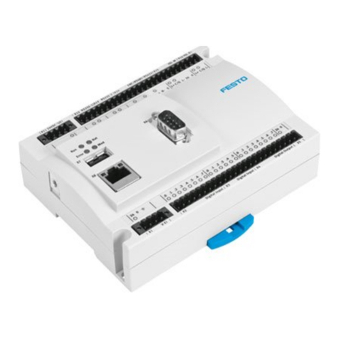
Festo CP-FB13-E User manual

Description
Programming and
diagnosis
CP field bus
node 13
Field bus protocol
PROFIBUS-DP
as per EN 50170
(DIN 19245)
Type CP-FB13-E
Description
165 213
en 9910c
Compact performance


Contents and general safety instructions
I
Festo Festo P.BE CP FB13-E-EN en 9910c
Authors U. Reimann, H.-J. Drung......................
Editors H.-J. Drung, M.Holder........................
Original de.......................................
Translation transline Deutschland GmbH...............
Layout Festo AG & Co., Dept. KG-GD...................
Type setting DUCOM................................
Edition en 9910c...................................
Title Manual-EN...................................
Designation Festo P.BE CP FB13-E-EN..................
Order-no. 165 213.................................
E(Festo AG & Co., D-73726 Esslingen, Federal Republic of
Germany, 2000)
Internet: http://www.festo.com
E-Mail: service_international@festo.com
The copying, distribution and utilization of this document as
well as the communication of its contents to others without
expressed authorization is prohibited. Offenders will be held
liable for the payment of damages. All rights reserved, in par-
ticular the right to carry out patent, utility model or orna-
mental design registrations.

Contents and general safety instructions
II Festo Festo P.BE CP FB13-E-EN en 9910c

Contents and general safety instructions
III
Festo Festo P.BE CP FB13-E-EN en 9910c
Contents
Designated use V........................................................
Target group VI..........................................................
Service VI...............................................................
Notesontheuseofthismanual VI...........................................
Important user instructions VII..............................................
1. Installation 1-1...................................................
1.1 General instructions 1-3.............................................
1.2 Setting the DIL switch elements 1-4...................................
1.2.1 Setting the field bus address 1-7......................................
1.3 Field bus baud rate and field bus length 1-10............................
1.3.1 Branch line length 1-11..............................................
1.4 Connecting the CP modules 1-12.......................................
1.5 Connecting the operating voltage 1-13..................................
1.6 Connecting the PROFIBUS DP interface 1-14.............................
1.6.1 Screening/shield connection 1-15......................................
1.6.2 Bus termination with terminating resistors 1-16..........................
1.6.3 Connection for optical-fibre waveguide 1-18.............................
2. Commissioning 2-1................................................
2.1 Preparing the CP system for operation on the PROFIBUS-DP 2-3............
2.1.1 Operating voltage 2-3...............................................
2.1.2 Saving the string assignment 2-3.....................................
2.1.3 Compiling the configuration list 2-4...................................
2.1.4 General information 2-5.............................................
2.2 Configuration with a Siemens master 2-13...............................
2.2.1 Preparations for COM PROFIBUS 3.x and 5.0 2-13.........................
2.2.2 Station selection with COM PROFIBUS 3.x 2-15...........................
2.2.3 Station selection with COM PROFIBUS 5.0 2-19...........................
2.2.4 Input and output address 2-23........................................
2.2.5 STEP 7 V4.x / 5.0 – Hardware configurator 2-25..........................
2.2.6 Commissioning the CP system on the PROFIBUS-DP 2-35...................

Contents and general safety instructions
IV Festo Festo P.BE CP FB13-E-EN en 9910c
2.3 Operation with the general DP master 2-37..............................
2.3.1 Bus start 2-37......................................................
2.3.2 Send parametrizing data 2-38.........................................
2.3.3 Send configuration data 2-39.........................................
2.3.4 Request diagnostic information 2-41...................................
2.3.5 Cyclic exchange of data 2-41..........................................
2.3.6 Summary of implemented functions and service access points (SAP) 2-43.....
2.3.7 Bus parameter/reaction times 2-44....................................
2.3.8 Transmission times on the PROFIBUS-DP 2-44............................
2.4 Device data base (GSD) 2-45..........................................
3. Diagnosis 3-1.....................................................
3.1 LED displays on the bus node 3-3.....................................
3.1.1 Normal operating status 3-4.........................................
3.1.2 Diagnosis Operating voltage POWER or POWER V 3-5.....................
3.1.3 Diagnosis LED BUS ERROR 3-6.......................................
3.2 Test of the valves 3-7...............................................
3.3 Diagnosis via PROFIBUS-DP 3-9......................................
3.3.1 Diagnostic words 3-9...............................................
3.3.2 Diagnostic information 3-12...........................................
3.4 Error treatment 3-17.................................................
3.4.1 General DP master 3-18..............................................
3.4.2 Siemens SIMATIC S5/S7 3-18.........................................
3.5 Online diagnosis with COM Profibus 5.0 3-21.............................
3.6 Online diagnosis with STEP 7 (version 5.0) 3-22..........................
3.6.1 Diagnostic buffer STEP 7 (version 4.x, 5.0) 3-22..........................
3.6.2 Device-specific diagnosis with STEP 7 (version 5.0) 3-24...................
3.7 Short circuit/overload 3-26...........................................
3.7.1 Output module 3-26.................................................
3.7.2 Short circuit in the sensor supply at an input module 3-27..................
A. Specifications and index A-1.........................................
A.1 Technical specifications Field bus node CP FB13-E A-3....................
A.2 Index A-5.........................................................
Contents and general safety instructions
V
Festo Festo P.BE CP FB13-E-EN en 9910c
Designated use
The CP field bus node type CP-FB13-E described in this man-
ual has been designed exclusively for use as a slave on the
PROFIBUS-DP. CP modules from Festo can be connected to CP
field bus node CP-FB13-E. The CP node may only be used as
follows:
– in accordance with designated use
– in its original state
– without any modifications by the user
– in faultless technical condition.
If additional commercially-available components such as sen-
sors and actuators are connected, the specifiedlimits for pres-
sures, temperatures, electrical data, torques, etc. must not
be exceeded.
Please observe the standards specified in the relevant
chapters and comply with technical regulations, as well as
with national and local regulations.

Contents and general safety instructions
VI Festo Festo P.BE CP FB13-E-EN en 9910c
Target group
This manual is intended exclusively for technicians trained in
control and automation technology, who have experience in
installing, commissioning, programming and diagnosing PRO-
FIBUS-DP slaves.
Service
Please consult your local Festo repair service if you have any
technical problems.
Notes on the use of this manual
This manual contains specific information on installing, com-
missioning, programming and diagnosingCP field bus node
FB13 for PROFIBUS-DP in accordance with EN 50170 (DIN
19245).
A CD ROM with device databases and bitmaps is supplied
with this manual. Information on the contents can be found in
the file “readme”.
InformationonfurtherCPmodulescanbefoundintheman-
ual for the relevant module. A summary is shown in fig. 0/1.

Contents and general safety instructions
VII
Festo Festo P.BE CP FB13-E-EN en 9910c
Important user instructions
Danger categories
This manual contains instructions on the possible dangers
which may occur if the product is not used correctly. These
instructions are marked (Warning, Caution, etc), printed on a
shaded background andmarked additionally with a picto-
gram. A distinction is made between the following danger
warnings:
Warning
... This means that failure to observe this instruction may
result in serious personal injury or damage to property.
Caution
... This means that failure to observe this instruction may
result in personal injury or damage to property.
Please note
... This means that failure to observe this instruction may
result in damage to property.
The following pictogram marks passages in the text which
describe activities with electrostatically sensitive compo-
nents.
Electrostatically sensitive components may be damaged if
they are not handled correctly.

Contents and general safety instructions
VIII Festo Festo P.BE CP FB13-E-EN en 9910c
Marking special information
The following pictograms mark passages in the text contain-
ing special information.
Pictograms
Information:
Recommendations, tips and references to other information
sources.
Accessories:
Information on necessary or sensible accessories for the
Festo product.
Environment:
Information on environment-friendly use of Festo products.
Text markings
SThe bullet indicates activites which may be carried out in
any order.
1. Figures denote activities which must be carried out in the
numerical order specified.
– Hyphens indicate general activities.

Contents and general safety instructions
IX
Festo Festo P.BE CP FB13-E-EN en 9910c
Manuals on the CP system Peripherals
Descrip-
t
i
“CP system, installation and commissioning”
tion
Contents General basic information on the method of operation, fitting, installa-
tion and commissioning ofCP systems.
Descrip-
tion
“CP field bus node,
programming and diag-
nosis”
“CPA valve ter-
minal, pneu-
matics” or “CPV
valve terminal,
pneumatics”
“CP modules, elec-
tronics”
Contents Special information on
commissioning, pro-
gramming and diag-
nosing related to the
node used.
Information on fit-
ting, installing and
commissioning
CPA or CPV valve
terminals
Information on fitting,
installing and commis-
sioning CP I/O modules
b
b
b
b
Fig. 0/1: Manuals on the CP system

Contents and general safety instructions
XFesto Festo P.BE CP FB13-E-EN en 9910c
The following product-specific terms and abbreviations are
used in this manual:
Term/abbreviation Meaning
Adigital output
Busy bit Enable bit, for analysing data exchange with the CP system
CP cable Special cable for coupling the various CP modules
CP connection Plug or socket on the CP modules which enables the modules to be
connected with the CP cable
CP modules Common term for various modules which can be incorporated in a CP
system
CP system Complete system consisting of CP field bus node and P modules
Edigital input
I/O modules Common term for the CP modules which provide digital inputs and
outputs (CP input modules and CP output modules)
I/Os digital inputs and outputs
Node CP field bus node with/without field bus connection to which the I/O
modules are connected
Octet Number of address bytes assigned by the CP system
PLC/IPC Programmable logic controller/industrial PC
SAVE button: Save the current string assignment (connected I/Os);
When the CP system is restarted, the last saved string assignment will
be compared with thecurrent string assignment. Deviations will be
indicated by flashing LEDs.
String Total number of I/O modules connected together on one CP connection
of the field bus node
String assignment Total number of all the I/O modules connected via strings to a CP field
bus node (0...3)

Installation
1-1
Festo Festo P.BE CP FB13-E-EN en 9910c
Chapter 1

1. Installation
1-2 Festo Festo P.BE CP FB13-E-EN en 9910c
Contents
1.1 General instructions 1-3.............................................
1.2 Setting the DIL switch elements 1-4...................................
1.2.1 Setting the field bus address 1-7......................................
1.3 Field bus baud rate and field bus length 1-10............................
1.3.1 Branch line length 1-11..............................................
1.4 Connecting the CP modules 1-12.......................................
1.5 Connecting the operating voltage 1-13..................................
1.6 Connecting the PROFIBUS DP interface 1-14.............................
1.6.1 Screening/shield connection 1-15......................................
1.6.2 Bus termination with terminating resistors 1-16..........................
1.6.3 Connection for optical-fibre waveguide 1-18.............................

1. Installation
1-3
Festo Festo P.BE CP FB13-E-EN en 9910c
1.1 General instructions
Warning
Before carrying out installation and maintenance work,
switch off the following:
– the compressed air supply
– the operating voltage on the field bus node (pins 1
and 2)
– the load voltage supply to the valves.
You will thereby avoid:
– uncontrolled movements of loose tubing
– uncontrolled movements of the connected actuators
– undefined switching states of the electronics.
Caution
The node of the CP system contains electrostatically sensi-
tive components.
SDo not therefore touch any contacts.
SObserve the regulations for handling electrostatically
sensitive components.
You will then prevent the electronics in the node from being
damaged.
General information on installing the CP modules can be
found in the manual for the “CP system”.

1. Installation
1-4 Festo Festo P.BE CP FB13-E-EN en 9910c
1.2 Setting the DIL switch elements
The DIL switch is under the cover on the field bus node.
Open and close the cover as follows:
SOpening: Remove the 2 screws in the cover. Lift up the
cover.
SClosing: Place the cover in position and tighten the screws
by hand.
Caution
Tighten the screws of the switch cover only by hand.
Warning
SBefore commissioning:
Make sure that switch elements 3..6 are set at the posi-
tion PROFIBUS-DP.
SDuring operation:
Do not modify the settings of the DIL switches during oper-
ation.
You will thereby avoid undesired movements of the con-
nected actuators.

1. Installation
1-5
Festo Festo P.BE CP FB13-E-EN en 9910c
1Cover screws
2DIL switch
1
2
1
Fig. 1/1: Position of DIL switch

1. Installation
1-6 Festo Festo P.BE CP FB13-E-EN en 9910c
Dual inline switch
Set the following functions on the DIL switch:
– the hundreds-figure of the field bus address
– Field bus protocol PROFIBUS-DP:
Switch elements 3..6 must be set to the lower positions in
order that the field bus protocol PROFIBUS-DP is set.
DIL switch (factory setting) Switch element Method of operation
1Field bus address
ON: Field bus address >100
OFF Field bus address <100
2Diagnostic message VVAL/VOFF
ON: active
OFF: inactive
3Field bus protocol PROFIBUS-DP
ON: must be set to ON
OFF: reserved
4Field bus protocol
ON: must be set to ON
OFF: reserved
5Field bus protocol
ON: must be set to ON
OFF: reserved
6Field bus protocol
ON: reserved
OFF: must be set to OFF

1. Installation
1-7
Festo Festo P.BE CP FB13-E-EN en 9910c
1.2.1 Setting the field bus address
Please note
The field bus addresses of the CP system cannot be modi-
fied by the DP master. The CP system can only be ad-
dressed by the field bus address set on the address selec-
tor switches.
1Address selector
switch for the
UNITS-figure
2Address selector
switch for the
TENS-figure
3Address selector
switch for the
HUNDREDS-
figure
6
5
2
789
0
1
3
4
6
5
2
789
0
1
3
4
1
2
3
Fig. 1/2: Setting the field bus address on the address selec-
tor switches

1. Installation
1-8 Festo Festo P.BE CP FB13-E-EN en 9910c
You can set the field bus address of the CP system with the
two round address selector switches and DIL switch element
no. 1. The switches are numbered from 0...9. The arrow indi-
cates the units or tens figure of the field bus address set.
Summary of possible field bus addresses
Please note
Field bus addresses may only be assigned once per PROFI-
BUS-DP interface.
Observe any possible limitations as regards the assign-
ment of field bus addresses by your DP master.
Recommendation:
Assign the field bus addresses in ascending order. If necess-
ary, assign the field bus addresses to suit the machine struc-
ture of your system.
Permitted field bus addresses 0; ...; 125
Other manuals for CP-FB13-E
6
Table of contents
Other Festo Control System manuals

Festo
Festo EduTrainer 8071407 User manual

Festo
Festo CMCA series User manual

Festo
Festo Checkbox Compact CHB-C-X User manual

Festo
Festo CPX-E Parts list manual

Festo
Festo Controller CECC-LK Parts list manual

Festo
Festo CMXR-C1 Operating and installation instructions

Festo
Festo CMCA-...-B Series User manual

Festo
Festo CPX-AP Series User manual

Festo
Festo LOGO! 8 TP EduTrainer User manual

Festo
Festo ZSB-1/8-B User manual