Leica IP S User manual

Leica IP S
Printer for slides
The Pathology Company
Instructions for Use
English
Order No.: 14 0601 80101 - Revision I
Always keep this manual near the instrument.
Read carefully before working with the instrument.
Version 2.0, Revision I - 02.2018


3
Leica IP S
Note
The information, numerical data, notes and value judgments contained in this Instructions for Use
represent the current state of scientific knowledge and state-of-the-art technology as we understand it
following thorough investigation in this field.
We are under no obligation to update the present Instructions for Use periodically and on an ongoing
basis according to the latest technical developments, nor to provide our customers with additional
copies, updates etc. of this Instructions for Use.
To the extent permitted in accordance with the national legal system as applicable in each individual
case, we shall not be held liable for erroneous statements, drawings, technical illustrations etc.
contained in this Instructions for Use. In particular, no liability whatsoever is accepted for any financial
loss or consequential damage caused by or related to compliance with statements or other information
in this Instructions for Use.
Statements, drawings, illustrations and other information regarding the contents or technical details of
the present Instructions for Use are not to be considered warranted characteristics of our products.
These are determined only by the contract provisions agreed between ourselves and our customers.
Leica reserves the right to change technical specifications as well as manufacturing processes without
prior notice. Only in this way is it possible to continuously improve the technology and manufacturing
techniques used in our products.
This document is protected under copyright laws. All copyrights to this documentation are held by Leica
Biosystems Nussloch GmbH.
Any reproduction of text and illustrations (or of any parts thereof) by means of print, photocopy,
microfiche, web cam or other methods – including any electronic systems and media – requires express
prior permission in writing by Leica Biosystems Nussloch GmbH.
For the instrument serial number and year of manufacture, please refer to the nameplate on the back of
the instrument.
Leica Biosystems Nussloch GmbH
Heidelberger Str. 17 - 19
D-69226 Nussloch
Germany
Tel.: +49 - (0) 6224 - 143 0
Fax: +49 - (0) 6224 - 143 268
Web: www.LeicaBiosystems.com

4Version 2.0, Revision I
Table of Contents
1. Important Information ................................................................................................................................ 6
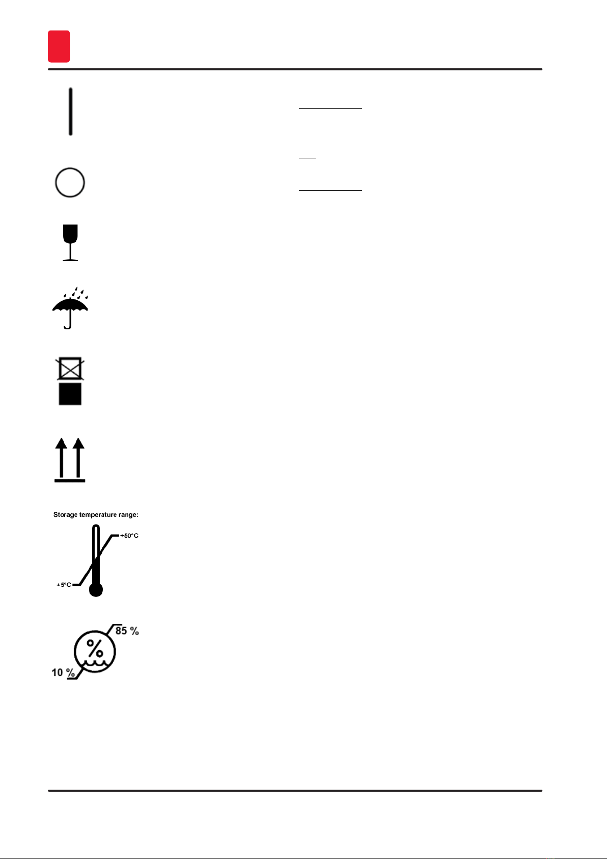
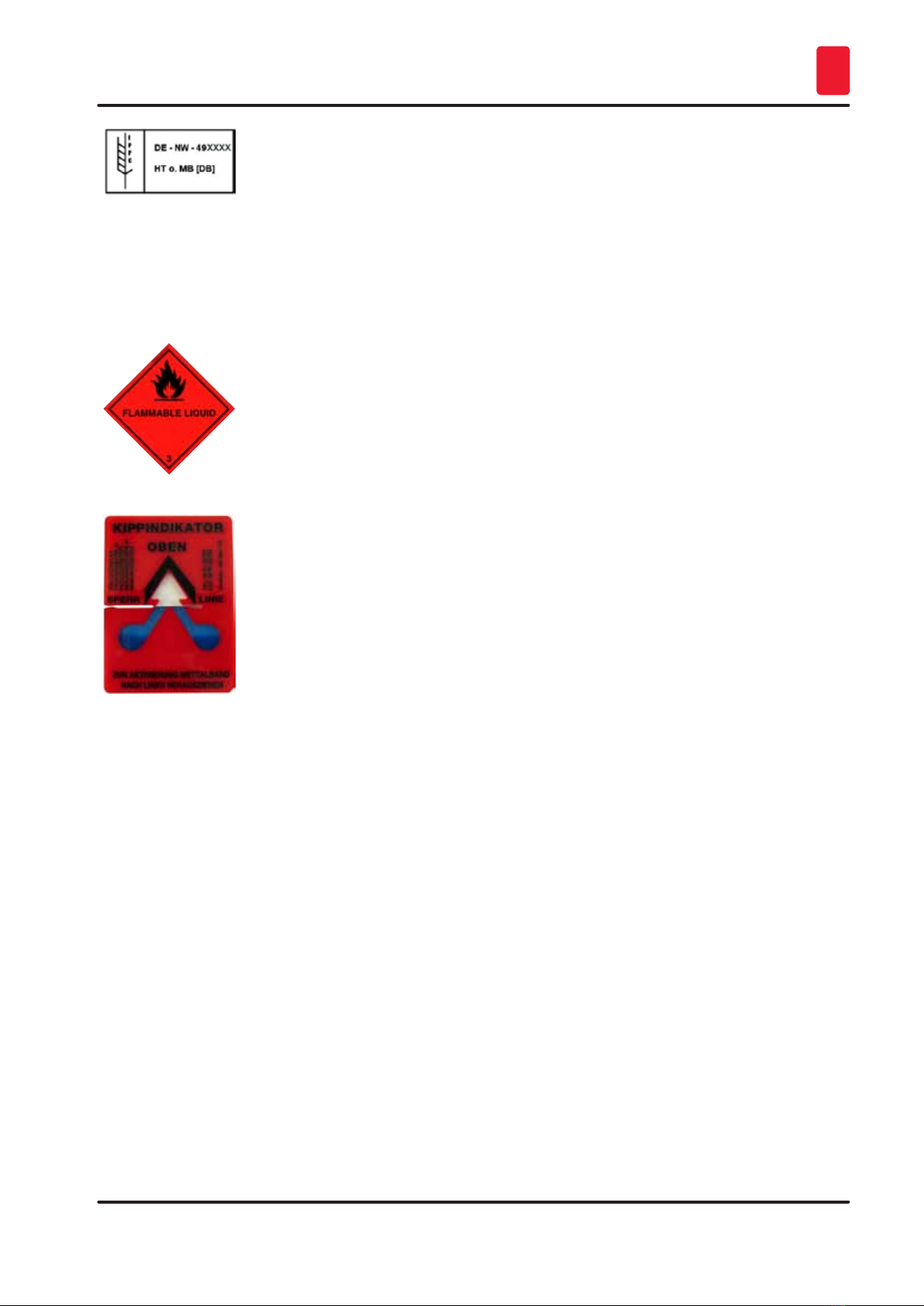
1.1 Symbols and their meanings.......................................................................................................................... 6
1.2 Qualification of personnel.............................................................................................................................. 9
1.3 Intended use of instrument............................................................................................................................ 9
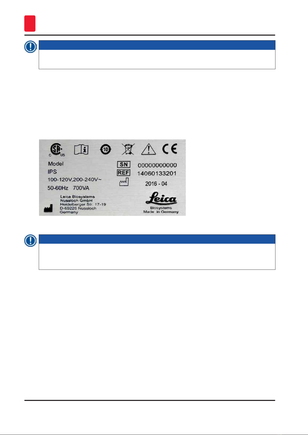
1.4 Instrument type.............................................................................................................................................. 10
2. Safety .......................................................................................................................................................... 11
2.1 Safety instructions......................................................................................................................................... 11
2.2 Warnings......................................................................................................................................................... 12
3. Instrument Components and Specifications........................................................................................ 14
3.1 Overview – instrument.................................................................................................................................. 14
3.2 Technical data................................................................................................................................................ 17
3.3 Print specifications........................................................................................................................................ 18
3.3.1 Requirements for specimen slides ............................................................................................................. 19
3.3.2 Print specifications........................................................................................................................................ 20
3.3.3 Printing bar code ........................................................................................................................................... 21
4. Instrument Setup....................................................................................................................................... 24
4.1 Site requirements .......................................................................................................................................... 24
4.2 Unpacking the instrument............................................................................................................................ 24
4.2.1 Installing the printer...................................................................................................................................... 26
4.3 Standard delivery........................................................................................................................................... 27
4.4 Installing the manual unload station .......................................................................................................... 28
4.5 Automated unload station (optional).......................................................................................................... 29
4.6 Installing/exchanging the flash bulb .......................................................................................................... 30
4.7 Filling and inserting the magazines ............................................................................................................ 33
4.8 Electrical connection.................................................................................................................................... 34
4.9 Exchanging the transport cartridge for an ink cartridge ........................................................................ 36
4.10 Installing the printer driver........................................................................................................................... 42
5. Operation.................................................................................................................................................... 43
5.1 Control panel functions................................................................................................................................. 43
5.2 Display indications ........................................................................................................................................ 49
5.3 Alarm functions.............................................................................................................................................. 50
5.4 Printer driver settings ................................................................................................................................... 51
6. Cleaning and Maintenance..................................................................................................................... 55
6.1 Cleaning the instrument................................................................................................................................ 55
6.2 Cleaning the print head................................................................................................................................. 57
6.3 Exchanging the cartridge............................................................................................................................. 60
6.3.1 Removing the used ink cartridge ................................................................................................................ 60
6.3.2 Inserting the new ink cartridge................................................................................................................... 61
6.3.3 Removing the protective cap....................................................................................................................... 61
6.4 General maintenance.................................................................................................................................... 61
6.5 Storing the instrument .................................................................................................................................. 61
7. Troubleshooting ........................................................................................................................................ 67

5
Leica IP S
Table of Contents
7.1 Malfunctions................................................................................................................................................... 67
7.2 Status messages............................................................................................................................................ 68
7.3 Error messages.............................................................................................................................................. 69
7.4 Changing the flash bulb................................................................................................................................ 72
7.5 Power failure.................................................................................................................................................. 72
7.6 Replacing the secondary fuses................................................................................................................... 73
8. Warranty and Service .............................................................................................................................. 75
9. Decontamination Certificate .................................................................................................................. 76

6Version 2.0, Revision I
Important Information
1
1. Important Information
1.1 Symbols and their meanings
Warning
Leica Biosystems GmbH assumes no liability for consequential loss or damage due to failure to observe
the following instructions, particularly in relation to transportation and package handling, and failure to
observe the instructions for handling the instrument carefully.
Symbol: Title of the symbol: Warning
Description: Warnings appear in a gray box and are marked by a
warning triangle.
Symbol: Title of the symbol: Note
Description: Notes, i. e. important user information, appear ina
gray box and are marked by an information symbol.
Symbol: Title of the symbol: Item number
→"Fig. 7 - 1"Description: Item numbers for numbering illustrations. Numbers in
red refer to item numbers in illustrations.
Symbol: Title of the symbol: Function key
START Description: Fuction keys to be pressed on the instrument are
displayed as capital letters and bold, black text.
Symbol: Title of the symbol: Software key and/or Display Messages
Ready Description: Software keys to be pressed on the display and/or
messages on the display are displayed as bold, gray
text.
Symbol: Title of the symbol: Warning, hot surface
Description: Instrument surfaces which become hot during
operation are marked with this symbol. Avoid direct
contact to prevent risk of burning.
Symbol: Title of the symbol: Warning, risk of electric shock
Description: Instrument surfaces or areas which become
energized during operation are marked with this
symbol. Therefore, direct contact is to be avoided.
Symbol: Title of the symbol: Manufacturer
Description: Indicates the manufacturer of the medical product.
Symbol: Title of the symbol: Manufacturing date
Description: Indicates the date when the medical device was
manufactured.
Symbol: Title of the symbol: RCM Compliance Mark

7
Leica IP S
Important Information 1
Description: The Regulatory Compliance Mark (RCM) indicates a
device’s compliance with applicable ACMA technical
standards of New Zealand and Australia - that is, for
telecommunications, radio communications, EMC
and EME.
Symbol: Title of the symbol: CE Compliance
Description: The CE marking is the manufacturer's declaration
that the medical product meets the requirements of
the applicable EC directives.
Symbol: Title of the symbol: CSA Statement (Canada/USA)
Description: The CSA test mark means that a product has
been tested and fulfills the applicable safety
and/or performance standards, including the
relevant standards defined or administered by the
American National Standards Institute (ANSI),
Underwriters Laboratories (UL), the Canadian
Standards Association (CSA), the National Sanitation
Foundation International (NSF) and others.
Symbol: Title of the symbol: China ROHS
Description: Environmental protection symbol of the China RoHS
directive. The number in the symbol indicates the
"Environment-friendly Use Period" of the product in
years. The symbol is used if a substance restricted
in China is used in excess of the maximum permitted
limit.
Symbol: Title of the symbol: WEEE Symbol
Description: The WEEE symbol, indicating separate collection
for WEEE - Waste of electrical and electronic
equipment, consists of the crossed-out wheeled bin
(§ 7 ElektroG).
Symbol: Title of the symbol: Alternating current
Symbol: Title of the symbol: Article number
Description: Indicates the manufacturer's catalog number so that
the medical device can be identified.
Symbol: Title of the symbol: Serial number
Description: Indicates the manufacturer's serial number so that a
specific medical device can be identified.
Symbol: Title of the symbol: Consult Instructions for Use
Description: Indicates the need for the user to consult the
Instructions for Use.
Symbol: Title of the symbol: ON (Power)

8Version 2.0, Revision I
Important Information
1
Description: The power supply is connected upon pushing the
power switch.
Symbol: Title of the symbol: OFF (Power)
Description: The power supply is disconnected upon pushing the
power switch.
Symbol: Title of the symbol: Fragile, handle with care
Description: Indicates a medical device that can be broken or
damaged if not handled carefully.
Symbol: Title of the symbol: Store dry
Description: Indicates a medical device that needs to be
protected from moisture.
Symbol: Title of the symbol: Stack limit
Description: It is not permitted to stack packages, and no loads
may be placed on top of the package.
Symbol: Title of the symbol: This way up
Description: Indicates correct upright position of the transport
package.
Symbol: Title of the symbol: Temperature limit for transport
Description: Indicates the temperature limits for transport to
which the medical device can be safely exposed.
Symbol: Title of the symbol: Humidity limitation for transport and storage
Description: Indicates the range of humidity for transport and
storage to which the medical device can be safely
exposed.
Symbol: Title of the symbol: IPPC symbol

9
Leica IP S
Important Information 1
Description: The IPPC symbol includes
IPPC symbol
• Country code to ISO 3166, e.g. DE for Germany
• Regional identifier, e.g. NW for North
Rhine-Westphalia
• Registration number, uniquely number beginning
with 49.
• Treatment method, e.g. HT (heat treatment)
Symbol: Title of the symbol: Inflammable (Packaging Label)
Description: Package labeling in accordance with German
Hazardous Freight Ordinance Road and Rail (GGVSE)/
European Agreement concerning the International
Carriage of Dangerous Goods by Road (ADR) for
transporting hazardous goods.
Class 3: "FLAMMABLE LIQUID"
Symbol: Title of the symbol: Tilt Indicator
Description: Indicator to monitor whether the shipment has been
transported and stored in upright position according
to your requirements. With a pitch of 60 ° or more,
the blue quartz sand flows into the arrow-shaped
indicator window and sticks there permanently.
Improper handling of the shipment is immediately
detectable and can be proven definitively.
1.2 Qualification of personnel
• The Leica IP S may be operated only by trained laboratory personnel.
• The instrument may be operated only according to the instructions contained in this Instruction for
Use.
1.3 Intended use of instrument
Leica IP S printer system for standard specimen slides.
• The instrument has been designed for use in pathology, histology, cytology, toxicology and similar
laboratories, and there only for standard specimen slides.
• Imprints of adequate quality and resistance to subsequent processing in tissue processors can only
be guaranteed when using the slides and reagents specified in (→p. 18 – 3.3 Print specifications).
• The instrument may be operated only according to the instructions contained in this Instructions for
Use.
Any other use of the instrument is considered improper

10 Version 2.0, Revision I
Important Information
1
Note
Proper and intended use includes the observance of all instructions in the operating manual and
compliance with all inspection and maintenance instructions.
1.4 Instrument type
All information provided in these Instructions for Use applies only to the instrument type indicated on
the title page.
A nameplate (→"Fig. 1") indicating the instrument serial number is attached to the back of the
instrument.
Fig. 1
Note
(→"Fig. 1") is provided as an example only and shows a valid nameplate for this instrument with
the necessary information about instrument type and power requirement. The precise data for the
various versions is specified in (→p. 17 – 3.2 Technical data).

11
Leica IP S
Safety 2
2. Safety
Warning
The safety and caution notes in this chapter must be observed at all times.
Make sure to read these instructions, even if you are already familiar with the operation and use of other
products.
2.1 Safety instructions
These Instructions for Use include important instructions and information related to the operating safety
and maintenance of the instrument.
The Instructions for Use are an important part of the product, and must be read carefully prior to startup
and use and must always be kept near the instrument.
This instrument has been built and tested in accordance with the safety regulations for electrical
measuring, control, regulating and laboratory devices.
To maintain this condition and ensure safe operation, the user must observe all notes and warnings
contained in these Instructions for Use.
Note
These Instructions for Use must be appropriately supplemented as required by the existing
regulations on accident prevention and environmental safety in the operator's country.
For current information about applicable standards, please refer to the CE declaration of conformity
on our Internet site:
http://www.LeicaBiosystems.com
Warning
The protective devices on both instrument and accessories may neither be removed nor modified.
Only authorized and qualified service personnel may repair the instrument and access the
instrument's internal components.
Use only the provided power cord. It must not be replaced with a different power cord. If the power
plug does not fit in your socket, contact our service.
Residual risks:
The instrument has been designed and constructed with the latest state-of-the-art technology and
according to recognized standards and regulations with regard to safety technology. Operating or
handling the instrument incorrectly can place the user or other personnel at risk of injury or can
cause damage to the instrument or other property. The machine may be used only as intended and
only if all of its safety features are in proper working condition. Malfunctions that impede safety must
be remedied immediately.

12 Version 2.0, Revision I
Safety
2
2.2 Warnings
The safety devices installed in this instrument by the manufacturer only constitute the basis for accident
prevention. Operating the instrument safely is, above all, the responsibility of the owner, as well as the
designated personnel who operate, service or repair the instrument.
To ensure trouble-free operation of the instrument, make sure to comply with the following instructions
and warnings.
Warnings – Transport and Installation
Warning
• Once unpacked, the instrument may be transported only in an upright position.
• Do not expose the instrument to direct light (window, bulbs with strong light)!
• Only connect the instrument to a grounded power socket. Do not interfere with the grounding
function by using an extension cord without a ground wire.
• Do not operate the instrument in rooms with explosion hazard.
• Condensation water may form in the instrument, if there is an extreme difference in temperature
between the warehouse and the installation site and if air humidity is high. If this is the case, wait
at least two hours before switching on the instrument. Failure to adhere to this waiting period may
result in damage to the instrument.
Warnings – Markings on the instrument itself
Warning
Markings on the instrument showing the warning triangle indicate that the correct operating
instructions (as defined in this Instructions for Use) must be followed when operating or replacing the
item marked.
Failure to adhere to these instructions may result in an accident, personal injury, damage to the
instrument or accessory equipment.
Some instrument surfaces, which become hot during operation are marked with this warning label:
Touching these surfaces may cause burns.

13
Leica IP S
Safety 2
Warnings – Instrument operation
Warning
• The instrument may be operated by trained laboratory personnel only. It must only be operated
for the purpose of its designated use and according to the instructions contained in these
Instructions for Use.
• The instrument is de-energized after disconnection of the power supply through the power cord
(power supply circuit breaker) - in emergencies, disconnect the power plug.
• Do not touch the chute during operation. Risk of injury.
• Do not open the reflector flap of the flash bulb while the instrument is ON – risk of burns and
blinding.
• The device operator is obligated to conform to the local workplace limit values and to document
them.
Warnings – Cleaning and maintenance
Warning
• Before any maintenance, switch off the instrument and unplug it from power supply.
• To clean the exterior surfaces, use a mild and ph-neutral commercial household cleaner. You may
not use: Alcohol, cleaning materials containing alcohol (glass cleaner!), abrasives, or solvents
containing acetone or xylene! The painted surfaces and the control panel of the instrument are
not resistant to xylene or acetone!
• While working and during cleaning, no liquid may get into the interior of the instrument.

14 Version 2.0, Revision I
Instrument Components and Specifications
3
3. Instrument Components and Specifications
3.1 Overview – instrument
1
5
3
7
2
6
4
Fig. 2
1Basic instrument
2Slide magazines
3Magazine no. 1
4Control panel
5Lid
6Cover – cartridge slot
7Unload station (manual)

15
Leica IP S
Instrument Components and Specifications 3
Front view without lid
4
2
3
8
1
3
6
2
7
1
5
Fig. 3
1Magazine receptacles nos. 1 - 3
2Cover – flash bulb
3Slide carrier
4Print head
5Magazine holder
6Feeding chute with cover
7Transfer point: chute --> slide carrier, with sensor
8Replacement plate with sealing lip

16 Version 2.0, Revision I
Instrument Components and Specifications
3
Rear panel and electrical connections
Fig. 4
1
5
3
7
26
4
8
1DIL switch
2External alarm jack
3Socket for printer cable
4Secondary fuses
5Power supply connection
6Main switch
7Transport cartridge / ink cartridge
8Drawer for broken glass
Note
Attention for (→"Fig. 4-7"). The instrument is delivered with the transport cartridge installed!
Prior to operation, the transport cartridge must be exchanged for an ink cartridge (→p. 36 – 4.9
Exchanging the transport cartridge for an ink cartridge).

17
Leica IP S
Instrument Components and Specifications 3
3.2 Technical data
General
Approvals: The instrument-specific approval marks are located at the
rear panel of the instrument, next to the nameplate.
Nominal supply voltages: 100 to 120 V ~ +/- 10 %
200 to 240 V ~ +/- 10 %
Nominal frequency: 50 to 60 Hz
Power fuse: 2x T 3.15 A L250 V
Maximum power draw at 100 - 120 V: 4.0 A
Maximum power draw at 200 - 240 V: 2.8 A
Leakage current at 240 V/50 Hz: ca. 2.4 mA
Nominal power: 700 VA
IEC 1010 classification: Protection class 1, pollution degree 2
Overvoltage installation category II
Operating elevation: up to max. 2000 m NN
A-weighted noise level: < 70 dB (A)
IP protection class (IEC 60529) IP20
Climatic conditions for the operation of the instrument:
Temperature: +15 °C to +30 °C
Relative humidity: 20 - 85 % - non-condensing
Climatic conditions for the storage and transport of the packaged instrument:
Storage temperature range: +5 °C to +50 °C
Transport temperature range: -29 °C to +50 °C
Relative humidity: 10 - 85 % - non-condensing
Dimensions and weight:
Dimensions of basic instrument
Width x depth: 475 x 650 mm
Height with magazine: 560 mm
Dimensions with unload station
connected:
Width x depth: 548 x 650 mm
Height with magazine: 655 mm
Basic instrument empty weight: approx. 28 kg
Weight, packed: approx. 65 kg
Unload station empty weight: approx. 14 kg
Weight, packed: approx. 32 kg
Performance:
Load capacity: up to 3 magazines,
up to 150 slides per magazine

18 Version 2.0, Revision I
Instrument Components and Specifications
3
Printing speed1:
Printing batch jobs: 14 slides/minute (two line printing)
Single-slide printing: 10 s per slide
Ink cartridge capacity2: approx. 60,000 printouts or 3.5 months
Flash bulb lifetime: approx. 150,000 flashes
Printing:
Print resolution3: 360 x 360 dpi / 180 x 180 dpi, adjustable
Printing medium: Glass specimen slide with coated field
76 x 26 mm, max. 1.2 mm thick
Print formats: Slide
Pressure surfaces: max. 25.4 x 18.0 mm
PC system requirements:
IBM-compatible PC
Processor clock frequency: min. 800 MHz
Main memory (RAM): min. 256 MB
Hard disk: min. 6 GB
CD-ROM drive
1 free serial port
Operating systems: Windows 7 (32 bit and 64 bit), Windows 8.1 (32 bit and 64 bit),
Windows 10 (32 bit and 64 bit)
1) Average value – exact speed in each individual case depending on system configuration and
software used.
2) Average value – exact number of slides in each individual case depending on quantity being
imprinted and on density of imprint.
3) Measured in addressable dots per inch.
3.3 Print specifications
Only standard specimen slides with imprintable colored edges (→"Fig. 5-1") can be imprinted in the
Leica IP S (→"Fig. 5").
Printing directly onto the glass is not possible.
Specimen slides with the following dimensions can be processed: 76 x 26 mm, max. 1.2 mm thick.

19
Leica IP S
Instrument Components and Specifications 3
1
Fig. 5
The texture of the slide print surface is extremely important for optimal print quality and durability.
The print surface varies considerably between manufacturers, color selection and coated (positively
charged) versus uncoated surfaces. They can even vary greatly from slide to slide in the same lot.
Colored print surfaces, other than pure white, contain pigments that help the ink spread evenly and
adhere strongly.
Specimen slides with a white printed surface should be checked for print quality and ink resistance
before purchase. Some slides have been coated over the print surface as well as the glass, which can
create problems with the adherence of the ink. These slides should also be tested for print quality and
ink adherence before purchase.
3.3.1 Requirements for specimen slides
• To reduce the amount of glass dust and the risk of mechanical failures, use only clipped corner slides
(45° angle on each corner, (→"Fig. 5")).
• Slides to be used in the printers must be stored appropriately in closed containers and protected from
dust and moisture.
• Positively charged slides stick to each other so they require special handling to insure reliable
mechanical handling by the instrument.
• When the print job is complete, the printed surface of the slide may be handled immediately. Please
be aware, however, that the special ink is alcohol-based and exposure to alcohol in combination with
physical contact (rubbing) could cause the print quality to degrade significantly.
Tested and recommended print media for the Leica IP S ink jet printer
Note
The use of other print media may result in unsatisfactory print quality and/or jamming of slides/
cassettes during the printing process!
If the slides/cassettes you are currently using are not listed below, please contact your local Leica
representative.

20 Version 2.0, Revision I
Instrument Components and Specifications
3
Specimen slides recommended by Leica are:
• Leica Snowcoat®Clipped Corner Slide
• Leica Clipped Corner X-tra®Adhesive Slides
• Apex Clipped Corner Slides
Warning
Slides made by other manufacturers must be tested before use.
The test must include the following steps:
• Mechanical compatibility with the instrument.
• Imprint quality.
• Chemical and mechanical resistance of the imprints against the reagents the slides will be
exposed to during the subsequent processing steps (→p. 23 – Resistance against reagents).
Important! Leica Biosystems assumes no responsibility whatsoever for any damages suffered as a
consequence of imprints of poor quality or imprints made with non-reagent-resistant ink.
3.3.2 Print specifications
Printing area
The printing area () parameters listed in the table below are defined in the printer driver.
Width Height
Format Dots mm Dots mm
Slide 360 25.4 256 18.0
Print resolution
The print head of the instrument has a preset resolution of 360 dpi in both directions (vertical and
horizontal). Each printed line has a maximum height of 128 dots. This corresponds to a value of 9.03 mm.
Therefore, a maximum of 2 lines can be printed on the slides. In horizontal direction, the printable
surface is limited only by the size of the object to be imprinted (→"Fig. 6"). The above values must be
taken into consideration when defining the print area ("paper size") in the application you are going to
print from.
1
Fig. 6
Other manuals for IP S
2
Table of contents
Other Leica Printer manuals