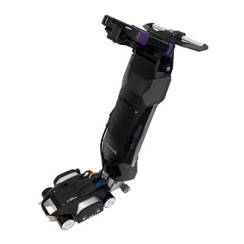
Leica T-Scan 5 User manual

Leica T‑Scan 5
User Manual
Version 1.2
English
All manuals and user guides at all-guides.com
all-guides.com

Introduction
Congratulations on the purchase of the Leica T-Scan 5.
This manual contains important safety directions as well as instructions for
setting up the product and operating it. Refer to for further information.
Read carefully through the User Manual before you switch on the product.
To ensure safety when using the system, please also observe the directions
and instructions contained in the User Manual and Safety Handbook issued
by:
•Machine manufacturer
•Robot manufacturer
•Sensor manufacturer
The model and serial number of your product are indicated on the type plate.
Always refer to this information when you need to contact your agency or
Leica Geosystems authorised service centre.
Product names are trademarks or registered trademarks and are property of
their respective owners.
This manual applies to the Leica T‑Scan used as accessory to the Leica Geo-
systems Absolute Tracker.
Name Description/Format
Leica T‑Scan User
Manual
In order to operate the product to a
basic level all instructions required are
contained in the User Manual. Provides
an overview of the product together
with technical data and safety direc-
tions.
–ü
Name Description/Format
Absolute Tracker
User Manual
All instructions required in order to
operate the product to a basic level are
contained in the Absolute Tracker User
Manual. Provides an overview of the
product together with technical data
and safety directions.
ü ü
Purchase
☞
Product Identifica-
tion
Trademarks
Validity of this
manual
Available docu-
mentation
2
All manuals and user guides at all-guides.com

Name Description/Format
Leica Integrated
Solutions Configu-
ration Manual
In order to operate the system in auto-
mation applications all instructions
required are contained in the Integrated
Solutions Configuration Manual. Pro-
vides an overview of Automation prod-
ucts together with technical data and
safety directions.
ü ü
T‑Scan Collect Ref-
erence Manual
Software Interface Reference Manual,
contains instructions for setting up and
operating the product.
–ü
Refer to the following resources for Absolute Tracker and T‑Products
documentation/software:
•http://www.leica-geosystems.com/metrology
Your feedback is important as we strive to improve the quality of our docu-
mentation. We request you to make specific comments as to where you
envisage scope for improvement.
Use the following e-mail address to send your suggestions:
support.ims@leica-geosystems.com
Leica Geosystems AG
Metrology Division
Moenchmattweg 5
5035 Unterentfelden
Switzerland
Phone +41-62-737 67 67
Fax +41-62-723 07 34
http://www.leica-geosystems.com/metrology
Feedback
Contact
3
All manuals and user guides at all-guides.com

Table of Contents
1 Safety Directions 5
1.1 General Introduction 5
1.2 Definition of Use 6
1.3 Limits of Use 6
1.4 Responsibilities 7
1.5 Hazards of Use 7
1.5.1 General 7
1.5.2 Additionally for the AC Power Supply 10
1.6 Laser Classification 11
1.7 Electromagnetic Compatibility EMC 12
1.8 FCC Statement, Applicable in U.S. 14
2 Description of the System 15
2.1 System Components 15
2.2 System Concept 15
2.3 Container Contents 15
2.4 T‑Scan Components 16
2.4.1 T‑Scan Sensor 16
2.4.2 T‑Scan holder 19
2.4.3 T‑Scan controller 19
2.5 General Operating Principle 20
3 Accessories 24
4 Operation 25
4.1 Setup 25
4.2 Measurement Strategy 25
4.3 Accuracy 29
4.3.1 Accuracy of Coordinates 29
4.3.2 Maximum Permissible Error (MPE) 30
4.3.3 Measurement Uncertainty 30
5 Check & Adjust 32
6 Care and Transport 33
6.1 Transport 33
6.2 Storage 33
6.3 Cleaning and Drying 33
6.3.1 Cleaning Optical Parts 33
6.4 Maintenance 35
7 Technical Data 36
8 Software Licence Agreement 39
Appendix A Abbreviations 40
Appendix B Regional Contact Addresses 41
4 Table of Contents
All manuals and user guides at all-guides.com

1 Safety Directions
1.1 General Introduction
The following directions enable the person responsible for the product, and
the person who actually uses the equipment, to anticipate and avoid opera-
tional hazards.
The person responsible for the product must ensure that all users understand
these directions and adhere to them.
Warning messages are an essential part of the safety concept of the instru-
ment. They appear wherever hazards or hazardous situations can occur.
Warning messages...
•make the user alert about direct and indirect hazards concerning the
use of the product.
•contain general rules of behaviour.
For the users‘ safety, all safety instructions and safety messages shall be
strictly observed and followed! Therefore, the manual must always be availa-
ble to all persons performing any tasks described here.
DANGER, WARNING, CAUTION and NOTICE are standardised signal words
for identifying levels of hazards and risks related to personal injury and prop-
erty damage. For your safety, it is important to read and fully understand the
following table with the different signal words and their definitions! Supple-
mentary safety information symbols may be placed within a warning message
as well as supplementary text.
Type Description
DANGER
Indicates an imminently hazardous situa-
tion which, if not avoided, will result in
death or serious injury.
WARNING
Indicates a potentially hazardous situation
or an unintended use which, if not avoided,
could result in death or serious injury.
CAUTION
Indicates a potentially hazardous situation
or an unintended use which, if not avoided,
may result in minor or moderate injury.
NOTICE
Indicates a potentially hazardous situation
or an unintended use which, if not avoided,
may result in appreciable material, financial
and environmental damage.
☞Important paragraphs which must be
adhered to in practice as they enable the
product to be used in a technically correct
and efficient manner.
Description
About Warning
Messages
Safety Directions 5
All manuals and user guides at all-guides.com

1.2 Definition of Use
•Usage as accessory to the Leica Absolute Tracker.
•Digitising of surfaces and character lines.
•Transmission of coordinates between the Absolute Tracker and the
T‑Scan for inspection and build measurements.
•Use of the product without instruction.
•Use outside of the intended use and limits.
•Disabling safety systems.
•Removal of hazard notices.
•Opening the product using tools, for example screwdriver, unless this is
permitted for certain functions.
•Modification or conversion of the product.
•Use after misappropriation.
•Use of products with recognizable damages or defects.
•Use with accessories from other manufacturers without the prior
explicit approval of Leica Geosystems.
•Inadequate safeguards at the working site.
•Deliberate dazzling of third parties.
•Controlling of machines, moving objects or similar monitoring applica-
tion without additional control and safety installations.
WARNING
Unauthorised modification of automatic machines and robots by
mounting or installing the product.
This action may alter the function and safety of the machine
Precautions:
▶Follow the instructions of the machine/robot manufacturer.
▶If no appropriate instruction is available, ask machine/robot manufac-
turer for instructions before mounting or installing the product.
1.3 Limits of Use
Suitable for use in an atmosphere appropriate for permanent human habita-
tion: not suitable for use in aggressive or explosive environments.
DANGER
Working in hazardous areas, or in close proximity to electrical installa-
tions or similar situations.
Life risk.
▶Local safety authorities and safety experts must be contacted before
working in hazardous areas, or in close proximity to electrical installa-
tions or similar situations by the person responsible for the product.
Suitable for use in dry environments only and not under adverse conditions.
Intended use
Reasonably fore-
seeable misuse
Environment
Environment
6 Safety Directions
All manuals and user guides at all-guides.com
all-guides.com

1.4 Responsibilities
Leica Geosystems AG, CH-9435 Heerbrugg, hereinafter referred to as Leica
Geosystems, is responsible for supplying the product, including the user man-
ual and original accessories, in a safe condition.
The person responsible for the product has the following duties:
•To understand the safety instructions on the product and the instruc-
tions in the user manual.
•To ensure that it is used in accordance with the instructions.
•To be familiar with local regulations relating to safety and accident pre-
vention.
•To inform Leica Geosystems immediately if the product and the applica-
tion becomes unsafe.
•To ensure that the national laws, regulations and conditions for the
operation of the product are respected.
1.5 Hazards of Use
1.5.1 General
WARNING
Unqualified installation on automatic machines and robots
This action may result in personal or material damage.
▶This product may be installed on automatic machines and robots only
by an appropriately trained and qualified specialist.
CAUTION
Dropping, misusing, modifying, storing the product for long periods or
transporting the product
Watch out for erroneous measurement results.
Precautions:
▶Periodically carry out test measurements and perform the field adjust-
ments indicated in the User Manual, particularly after the product has
been subjected to abnormal use as well as before and after important
measurements.
Manufacturer of
the product
Person responsible
for the product
Safety Directions 7
All manuals and user guides at all-guides.com

CAUTION
Dropping the product
When being dropped, the product can cause personal injury and/or mechani-
cal damage.
Precautions:
▶Ensure to have a firm grip on the product before operating it.
CAUTION
Not properly secured accessories.
If the accessories used with the product are not properly secured and the
product is subjected to mechanical shock, for example blows or falling, the
product may be damaged or people can sustain injury.
Precautions:
▶When setting up the product, make sure that the accessories are cor-
rectly adapted, fitted, secured, and locked in position.
▶Avoid subjecting the product to mechanical stress.
WARNING
Inadequate securing of the working site.
This action can lead to dangerous situations, for example in traffic, on build-
ing sites and at industrial installations.
Precautions:
▶Always ensure that the working site is adequately secured.
▶Adhere to the regulations governing safety, accident prevention and
road traffic.
WARNING
Cables deployed on the ground
These cables can be a hazard to pedestrians or vehicular traffic.
Precautions:
▶Ensure the power cable, LAN cable or any other cables do not lie in the
path of pedestrian/vehicular traffic.
▶Use appropriate cable cover and/or warning signs.
8 Safety Directions
All manuals and user guides at all-guides.com

CAUTION
Powering up the product with no or partial cabling
This action may damage the product.
Precautions:
▶Before connecting the product to the power supply, ensure that the
installation and cabling of the entire system is completed.
WARNING
Improper disposal of the product
If the product is improperly disposed of, the following can happen:
•If polymer parts are burnt, poisonous gases are produced which may
impair health.
•If batteries are damaged or are heated strongly, they can explode and
cause poisoning, burning, corrosion or environmental contamination.
•By disposing of the product irresponsibly you may enable unauthorised
persons to use it in contravention of the regulations, exposing them-
selves and third parties to the risk of severe injury and rendering the
environment liable to contamination.
Precautions:
▶The product must not be disposed with household
waste.
Dispose of the product appropriately in accordance
with the national regulations in force in your country.
Always prevent access to the product by unauthorised
personnel.
Product-specific treatment and waste management information can be
received from your Leica Geosystems distributor.
Applies only for California. The product contains CR Lithium Cell(s) with per-
chlorate material inside – special handling may apply.
See http://www.dtsc.ca.gov/hazardouswaste/perchlorate/
WARNING
Improperly repaired equipment
Risk of injuries to users and equipment destruction due to lack of repair
knowledge.
Precautions:
▶Only Leica Geosystems authorised service centres are entitled to repair
these products.
☞
Safety Directions 9
All manuals and user guides at all-guides.com

1.5.2 Additionally for the AC Power Supply
WARNING
Unauthorised opening of the product
Either of the following actions may cause you to receive an electric shock:
•Touching live components
•Using the product after incorrect attempts were made to carry out
repairs
Precautions:
▶Do not open the product!
▶Only Leica Geosystems authorised service centres are entitled to repair
these products.
CAUTION
Using the wrong types of fuses
This action can damage the product.
Precautions:
▶If defect, the fuse of the product shall only be replaced by the same
type of fuse.
▶Unplug the power supply cord before replacing the fuse.
▶Refer to the relevant label of the product for information about the cor-
rect type of fuse.
WARNING
Electric shock due to no connection to ground
If unit is not connected to ground, death or serious injury can occur.
Precautions:
▶The power cable and power outlet must be grounded!
10 Safety Directions
All manuals and user guides at all-guides.com

WARNING
Electric shock due to use under wet and severe conditions
If unit becomes wet it may cause you to receive an electric shock.
Precautions:
▶If the product becomes humid, it must not be used!
▶Use the product only in dry environments, for example in buildings or
vehicles.
▶Protect the product against humidity.
1.6 Laser Classification
The following chapters provide instructions and training information about
laser safety according to international standard IEC 60825-1 (2014-05) and
technical report IEC TR 60825-14 (2004-02). The information enables the
person responsible for the product and the person who actually uses the
equipment, to anticipate and avoid operational hazards.
☞According to IEC TR 60825-14 (2004-02), products classified as
laser class 1, class 2 and class 3R do not require:
•laser safety officer involvement,
•protective clothes and eyewear,
•special warning signs in the laser working area
if used and operated as defined in this User Manual due to the low
eye hazard level.
☞National laws and local regulations could impose more stringent
instructions for the safe use of lasers than IEC 60825-1 (2014-05)
and IEC TR 60825-14 (2004-02).
The T‑Scan sensor contains the following types of LEDs:
Type of LED Laser class Classification
Status LEDs:
produce a visible LED
beam
Exempt Group IEC 62471 (2006-07)
Infrared LEDs:
produce an invisible
LED beam
Exempt Group IEC 62471 (2006-07)
A product classified as exempt group does not pose any hazard provided that
the product is used and maintained in accordance with this user manual.
The scanning module built into the product produces a visible red laser beam
which emerges from the scanning window.
The laser product described in this section is classified as laser class 2 in
accordance with:
General
Status LEDs and
Infrared LEDs
Scanning module
Safety Directions 11
All manuals and user guides at all-guides.com
all-guides.com

•IEC 60825-1 (2014-05): “Safety of laser products”
These products are safe for momentary exposures but can be hazardous for
deliberate staring into the beam. The beam may cause dazzle, flash-blindness
and after-images, particularly under low ambient light conditions.
Description Value
Wavelength 660 nm
Maximum radiant power < 1 mW
Pulse duration continuous wave
Pulse repetition frequency continuous wave
Beam divergence 0.784 rad × 0.003 rad
CAUTION
Laser beam
From a safety perspective, class 2 laser products are not inherently safe for
the eyes.
Precautions:
▶Avoid staring into the beam.
▶Avoid pointing the beam at other people or at animals.
007439_003
a
Power: 12V , 0.5A / 24V , 0.4A
Leica Geosystems AG
CH-9435 Heerbrugg
Manufactured:
Made in Switzerland
T-Scan 5 Rev. 1.3 576187
LLS1300000
Model:
Art.No.:
S.No.:
Complies with FDA performance standards for
laser products except for deviations pursuant to
Laser Notice No. 50, dated June 24, 2007.
Pav <1 mW cw, l=660 nm
IEC 60825-1:2014
MM.YYYY
a Laser class 2
Laser Radiation
Do not stare into the beam
Class 2 Laser Product
according to IEC 60825-1
(2014-05)
Pav <1mW cw
l= 660nm
007440_002
a
b
a Laser beam
b Exit for laser beam
1.7 Electromagnetic Compatibility EMC
The term Electromagnetic Compatibility is taken to mean the capability of the
product to function smoothly in an environment where electromagnetic radia-
Labelling
Description
12 Safety Directions
All manuals and user guides at all-guides.com

tion and electrostatic discharges are present, and without causing electro-
magnetic disturbances to other equipment.
WARNING
Electromagnetic radiation can cause disturbances in other equipment.
Although the product meets the strict regulations and standards which are in
force in this respect, Leica Geosystems cannot completely exclude the possi-
bility that other equipment may be disturbed.
▶The product is a Class A product. In a domestic environment this prod-
uct may cause radio interference in which case the user may be
required to take adequate measures.
CAUTION
Disturbances in other equipment
There is a risk that disturbances may be caused in other equipment if the
product is used with accessories from other manufacturers, for example field
computers, personal computers or other electronic equipment, non-standard
cables or external batteries.
Precautions:
▶Use only the equipment and accessories recommended by Leica Geo-
systems.
When combined with the product, they meet the strict requirements
stipulated by the guidelines and standards.
▶When using computers, two-way radios or other electronic equipment,
pay attention to the information about electromagnetic compatibility
provided by the manufacturer.
CAUTION
Disturbances caused by electromagnetic radiation can result in erro-
neous measurements.
Although the product meets the strict regulations and standards which are in
force in this respect, Leica Geosystems cannot completely exclude the possi-
bility that function of the product may be disturbed by intense electromag-
netic radiation, for example, near radio transmitters, two-way radios or diesel
generators.
Precautions:
▶Check the plausibility of results obtained under these conditions.
Safety Directions 13
All manuals and user guides at all-guides.com

CAUTION
Operating the product with connecting cables attached at only one of
their two ends
If the product is operated with connecting cables attached at only one of
their two ends, for example external supply cables, interface cables, the per-
mitted level of electromagnetic radiation may be exceeded and the correct
functioning of other products may be impaired.
Precautions:
▶While the product is in use, connecting cables, for example product to
external battery, product to computer, must be connected at both ends.
1.8 FCC Statement, Applicable in U.S.
WARNING
This equipment has been tested and found to comply with the limits for a
Class A digital device, pursuant to Part 15 of the FCC Rules.
These limits are designed to provide reasonable protection against harmful
interference when the equipment is operated in a commercial environ-
ment.
This equipment generates, uses, and can radiate radio frequency energy
and, if not installed and used in accordance with the instruction manual,
may cause harmful interference to radio communications. Operation of
this equipment in a residential area is likely to cause harmful interference
in which case the user will be required to correct the interference at his
own expense.
WARNING
Changes or modifications not expressly approved by Leica Geosystems for
compliance could void the user's authority to operate the equipment.
007506_003
Power: 48V DC, 100VA max.
T2 AH, 400V Rev.:2.0
Leica Geosystems AG
CH-9435 Heerbrugg
Manufactured:
Made in Switzerland
This device complies with part 15 of the FCC Rules. Operation is
subject to the following conditions:
(1) This device may not cause harmful interference, and
(2) this device mus accept any interference received, including
interference that may cause undesired operation.
T-Scan Controller Rev. 2.0
819828
CTL2000000
Model: Art.No.:
S.No.:
08.2017
Labelling
14 Safety Directions
All manuals and user guides at all-guides.com

2 Description of the System
2.1 System Components
The Leica T‑Scan system consists of:
•T‑Scan sensor
•T‑Scan controller
•T-Scan Collect software
The terms "Absolute Tracker" and "Laser Tracker" are used as synonyms for
the Leica Geosystems Absolute Tracker. The term "T‑Scan" is used as a syno-
nym for the Leica T‑Scan 5.
2.2 System Concept
007442_002
Component Description
T‑Scan sensor Used to measure clouds of points. The T‑Scan sensor
can be operated as a handheld scanner or can be
mounted onto a robot or machine.
T‑Scan controller Controls scan frequencies. Records and synchronises
measurement data.
2.3 Container Contents
007443_002
a
b
d
f
g
e
h
c
a Horizontal scanner
holder
b T‑Scan controller
c AC power supply
d T‑Scan sensor
e Calibration sphere
f Removable inlay
g LAN cable
h Trigger/Probe cable
Introduction
General
Container for
T‑Scan system
components
Description of the System 15
All manuals and user guides at all-guides.com

2.4 T‑Scan Components
2.4.1 T‑Scan Sensor
007444_001
a
b
d
c
a Aperture for laser beam
(scan line)
b Aperture for pilot beam
c Aperture for receiver
optics
d Trigger key
007445_001
a
b
d
c
e
f
g
a Status LED for T‑Scan
controller
b Trigger key (front side)
c Marker LED
d Stand-off indicator LED
e Status LED for Laser
Tracker
f Reflector
g Speaker
NOTICE
Too much strain on the cable when bending it for a prolonged time
Putting too much strain on the cable when bending it for a prolonged time
may damage the cable.
Precautions:
▶Ensure that the bending radius is not less than 8 cm when bending the
cable for a prolonged time.
Front view
Back view
16 Description of the System
All manuals and user guides at all-guides.com
all-guides.com

007509_001
Acoustical status information
To inform about the current measurement status of the sensor, the T‑Scan
can give an acoustical status information. For example, the following status
information is indicated by different acoustic signals:
•Laser Tracker beam locked on and ready to measure
•Measurement completed
•6DOF not available
•Laser beam broken
Optical status information
The T‑Scan can also give optical information to inform about the status of the
sensor and the communication to other system components:
007446_001
a
bc
a Stand-off indicator LED
b Status LED for T‑Scan con-
troller
c Status LED for Laser Tracker
The Stand-off indicator LED shows the following status cases:
LED Sta-
tus
Status information
Off Laser Tracker beam is not locked on or T‑Scan sensor is out-
side of working range
T‑Scan indicators
Stand-off indicator
LED
Description of the System 17
All manuals and user guides at all-guides.com

LED Sta-
tus
Status information
Maximum working distance, stand-off is at far end of work-
ing range
Mid working distance
Minimum working distance, stand-off is at close end of work-
ing range
The status LED for the Laser Tracker shows:
•the communication status between T‑Scan sensor and Laser Tracker
•the measurement status of the T‑Scan system
Colour Pattern Status information
LED OFF - No communication between T‑Scan and Laser
Tracker.
Green Static Communication to Laser Tracker is established.
T‑Scan system is ready to measure.
Red Static Laser Tracker beam is not locked onto T‑Scan.
T‑Scan system is not ready to measure.
Yellow Static Communication to Laser Tracker is established.
T‑Scan measurement is in process.
Green Blinking Communication to Laser Tracker is established.
T‑Scan is in sleep mode.
The status LED for the T‑Scan controller shows:
•the status of the T‑Scan controller (ON/OFF)
•the communication status between T‑Scan controller and T‑Scan sensor
Colour Pattern Status information
LED OFF - T‑Scan controller is OFF.
No communication between controller and sen-
sor
Red Blinking Power on
Yellow Blinking Booting
Green Blinking Successfully booted
Communication between T‑Scan controller and
sensor is okay.
Status LED for
Laser Tracker
Status LED for the
T‑Scan controller
18 Description of the System
All manuals and user guides at all-guides.com

Colour Pattern Status information
Green Static Computer software has connected to T‑Scan
controller.
2.4.2 T‑Scan holder
Use the horizontal scanner holder (a) as a safe storage place for the T‑Scan
sensor.
015904_001
a
a Horizontal scanner holder
2.4.3 T‑Scan controller
The T‑Scan controller is the control unit for the T‑Scan sensor. This device
controls the scan frequencies, records the measurement data and synchroni-
ses the scan data with the 6DOF measurements of the Absolute Tracker.
Front view
a
015306_001
a Power switch
Horizontal scanner
holder
Control unit for
T‑Scan sensor
Description of the System 19
All manuals and user guides at all-guides.com

Back view
007452_003
a
b
d
c
f
g
e
h
i
a Connector for trigger/probe
cable
b LAN connection to Laser
Tracker controller
c Connector for scanner
cable
d Fuse
e Power socket for:
MPS21 or MPB25
f Connector for trigger cable
g LAN connection to applica-
tion computer
h MPS21, power supply unit
i MPB25, external Li-Ion
battery: 37 V and 8.1 Ah
2.5 General Operating Principle
The T‑Scan sensor is a triangulation scanner using an optically amplified laser
line observed by a 2D imaging sensor.
The T‑Scan sensor has a working range (measurement depth) of approxi-
mately ±50 mm. The mid working distance is the distance from the housing
to the centre of the working range. This distance is also called Stand-off and
amounts approximately 150 mm. The usable scan width at stand-off is
approximately 100 mm.
007453_001
abc
d
e
a Minimum working distance
b Mid working distance
(stand-off)
c Maximum working distance
d Scan width at stand-off
e Working range
In order to facilitate the positioning of the T‑Scan sensor, the sensor emits a
pilot beam. The pilot beam intersects the laser beam at the centre of the
working range. If the pilot beam is underneath the scan line, the distance
between sensor and measuring object is too small. If the pilot beam is above
the scan line, the distance is too large.
Measurement
depth and scan
width
Positioning of the
T‑Scan sensor
20 Description of the System
All manuals and user guides at all-guides.com
Other manuals for T-Scan 5
2
Table of contents
Other Leica Scanner manuals

Leica
Leica Aperio GT 450 DX User manual

Leica
Leica BLK360 User manual

Leica
Leica ScanStation P30 User manual

Leica
Leica BLK360 User manual

Leica
Leica BLK2GO User manual

Leica
Leica BLK360 User manual

Leica
Leica ScanStation P30 Installation guide

Leica
Leica ScanStation P Series User manual

Leica
Leica Aperio GT 450 DX User manual

Leica
Leica BLK360 User manual