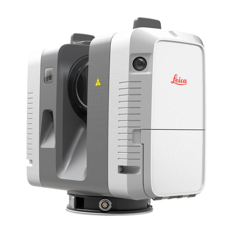
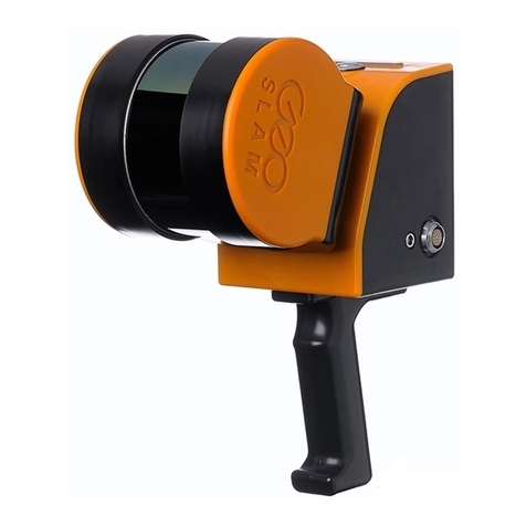
Leica ScanStation P30 Installation guide

ScanStation P30/40 & Cyclone
Basic Training Manual
August 2015


Introduction
Introduction
This training manual covers the basics on using Leica Geosystem’s
Terrestrial Laser Scanner Hardware as well as our Cyclone point cloud
processing software.
The course runs through the whole workflow from setting up the instrument and capturing your
scene to downloading and combining the captured data into a common coordinate system
(registration) all the way to extracting information and creating end-deliverables from this data.
The layout reflects the standard workflow progression as it is executed in the majority of cases.
elow is the basic flowchart on how a standard workflow progression looks like.
We believe that when you have been through these exercises you have sufficient information to
start and execute your own projects and understand the philosophy of the software well enough
to also use additional functionality within the software package which is not covered here.
All software parts are explained on example databases which are delivered with this class. This
allows you revisit and revise certain parts later on at your own pace and time.
Further information on specific items can always be found in the hardware user manuals and
system field manuals as well as the Cyclone Help.
All people involved in creating this documentation hope that you find this manual useful and find
yourself looking at it also in the future as a reference guide.
ASIC WORKFLOW CHART
Data Capture
&Transfer
Data Import
& Inspection Registration
Data
Organisation
& Cleanup
Creating
Deliverables Export


Table of Contents
1
Table of Contents
Module 1.0 - Scanning with ScanStation P30 ............................................................................... 1
1
HDS - ScanStation P30 ................................................................................................... 3
2
Set up the ScanStation P30 ...........................................................................................
3
MMI (Man Machine Interface) - Overview ..................................................................... 12
4
Operating P30 using Onboard Graphical Interface ........................................................ 31
5
Remote Control of the P30 .......................................................................................... 4
Data Management on P30 ............................................................................................ 53
7
Troubleshoot ............................................................................................................... 59
Module 2.0 - Introduction to Cyclone ........................................................................................... 1
1
Cyclone Navigator Window ............................................................................................. 3
2
Managing Databases ...................................................................................................... 5
3
Linking to / Loading an Existing Database ...................................................................... 8
4
Using the Online Help .................................................................................................. 10
5
Database Hierarchy ...................................................................................................... 11
Examine the Database’s Objects .................................................................................. 13
7
File Management .......................................................................................................... 21
Module 2.1 - Point Cloud Import .................................................................................................. 1
1
Importing Leica ScanStation data ................................................................................... 3
2
Importing HDS 7000 data (.zfs) ................................................................................... 12
3
Import of other scan file formats ................................................................................. 14
4
Import as Auto Align Project ......................................................................................... 15
5
Import MultiStation MS50 Data .................................................................................... 1
Using Batch Import tool ............................................................................................... 19
Module 3.0 - Basic Registration .................................................................................................... 1
1
Auto Alignment Registration (Cloud Constraints) ........................................................... 3
2
Visual Alignment Registration (Cloud Constraints) ........................................................ 13
3
Factors that determine the Effectiveness of PointCloud Constraints ............................ 22
4
Target Registration (Target constraints) ...................................................................... 25
5
Combined Registration ................................................................................................. 29
Module 3.1 - Applied Registration Techniques .............................................................................. 1
1
Getting Started .............................................................................................................. 3
2
Loading and importing Data ........................................................................................... 7
3
Preparation before registering Scans ........................................................................... 10
4
Registration ................................................................................................................. 17
5
Quality Check ............................................................................................................... 29
Geo Referencing .......................................................................................................... 33
7
Theory Excurse ............................................................................................................. 43
Module 4.0 - Organization & Visualization of point clouds ........................................................... 1
1
ScanWorld Explorer ........................................................................................................ 3
2
View Properties .............................................................................................................. 5
3
Unify a Point Cloud / ModelSpace ................................................................................. 12
4
Limit Box ...................................................................................................................... 15
5
User Coordinate System ............................................................................................... 19
Cutplanes and Half-Spaces ........................................................................................... 28
7
Review ......................................................................................................................... 34

2
Table of Contents
Module 4.1 - Texture Mapping ...................................................................................................... 1
1
Texture Mapping with imported images.......................................................................... 3
2
Texture Mapping with Cube-Maps ................................................................................ 1
Module 4.2 - Cyclone Keyplan ...................................................................................................... 1
1
Create a Keyplan ............................................................................................................ 3
2
Working with a KeyPlan .................................................................................................. 8
Module 4.3 - Cyclone TruSpace .................................................................................................... 1
1
Open and View a TruSpace ............................................................................................. 3
2
Tools and Functions within TruSpace .............................................................................
3
Review ......................................................................................................................... 13
Module 5.0 - Cyclone Basic Modelling ........................................................................................... 1
1
Point Cloud Selection ..................................................................................................... 2
2
Fitting and Editing Patches ............................................................................................. 8
3
Fitting Continued ......................................................................................................... 17
4
Further Editing ............................................................................................................. 29
Module 5.1 - Measurements ......................................................................................................... 1
1
Measurements ............................................................................................................... 2
2
Obtaining Measurements ............................................................................................... 4
3
Edit and Save Measurements ......................................................................................... 5
4
Copying Measurements .................................................................................................. 8
Module 5.2 - Mesh Functions ....................................................................................................... 1
1
Mesh Creation and Editing ............................................................................................. 3
2
Creating Deliverables from Meshes ................................................................................ 9
3
Enhanced TIN Mesh Creation and Editing ..................................................................... 18
4
Creating a Uniform Sample Grid Pattern ....................................................................... 27
Module 5.3 - Alignments & Sections ............................................................................................ 1
1
Getting Started .............................................................................................................. 3
2
Remove Car Noise .......................................................................................................... 7
3
Create an Alignment .................................................................................................... 11
4
Create Sections ............................................................................................................ 14
5
Sections Manager ......................................................................................................... 15
Review ......................................................................................................................... 18
Module .0 - Export / Import ........................................................................................................ 1
1
Image Export .................................................................................................................. 2
2
Export ............................................................................................................................ 4
3
Import ............................................................................................................................ 7
4
COE – Cyclone Object Exchange ................................................................................... 11
5
Export pcE Application Files .......................................................................................... 12
Module .1 - Animation ................................................................................................................ 1
1
Defining an Animation Path ........................................................................................... 2
2
Editing the Path ............................................................................................................. 4
3
Editing the Frames ......................................................................................................... 4
4
Preview the Animation ...................................................................................................
5
Generating the Frames ................................................................................................... 7

Agenda
1
-
4
Training Course Agenda
Day 1 - Tuesday
Morning Session (09:00am – 12:00pm)
09:00 Introduction: Student and teac er introduction.
Overview of t e training sc edule and training goals.
09:15 Module 1.0: Overview Scanning, Targets, Connect Scanners
09:45 Module 1.1: Scanning wit ScanStation P30 / P40
10:30 Break
10:45 Module 1.1: Scanning wit ScanStation P30 / P40 cont.
12:00 Lunc Break
Afternoon Session (01:00pm – 5:00pm)
01:00 Module 2.0: Introduction to Cyclone
02:30 Break
02:45 Module 2.1: Point Cloud Import
03:45 Module 3.0: Scanning and Registration Basics
Placing and using targets, scanning from different positions for registration. Registering
to survey control.
05:00 End of Day 1

2
-
4
Agenda
Training Course Agenda
Day 2 - Wednesday
Morning Session (09:00am – 12:00pm)
09:00 Module 3.1: Basic Pointcloud Registration
10:30 Break
10:45 Module 3.2: Applied Registration Tec niques
12:00 Lunc Break
Afternoon Session (01:00pm – 5:00pm)
01:00 Module 3.2: Applied Registration Tec niques cont.
02:30 Break
02:45 Module 4.2: Cyclone Keyplan
03:15 Module 4.3: Cyclone TruSpace
03:45 Module 4.4: Cyclone Publis er & TruView
05:00 End of Day 2

Agenda
3
-
4
Training Course Agenda
Day 3 - T ursday
Morning Session (09:00am – 12:00pm)
09:00 Module 4.0: Organization & Visualization of Pointclouds
10:30 Break
10:45 Module 4.0: Organization & Visualization of Pointclouds cont.
11:15 Module 5.0: Cyclone Basic Modelling
12:00 Lunc Break
Afternoon Session (01:00pm – 5:00pm)
01:00 Module 5.0: Cyclone Basic Modelling cont.
02:30 Break
02:45 Module 5.1: Measurements
03:00 Module 5.2: Mes Functions
04:00 Module 5.3: Alignments & Sections
05:00 End of Day 3

4
-
4
Agenda
Training Course Agenda
Day 4 - Friday
Morning Session (09:00am – 12:00pm)
09:00 Execution of Scanning Project in t e Field
11:30 Import Scans
12:00 Lunc Break
Afternoon Session (01:00pm – 4:00pm)
01:00 Registration/ Aligning of Scans from t e morning session
Review of scanning project
01:30 Module 6.0: Export / Import
02:00 Module 6.1: Animation
02:30 Customizing Cyclone
03:00 optional: CloudWorx AutoCAD Demo
03:30 Review and Participants’ Feedback
04:00 End of Day 4

Scanner & Scanning Features
Module 1.0
-
Scanning with ScanStation
P30
1
-
60
Module 1.0 - Scanning with ScanStation P30
Introduction
The Leica ScanStation P30 is the industry’s best performing ultra-high speed and easy to learn
“ ave-Form-Digitized” scanner. The scanner is equipped with survey grade accuracy, range and
field-of-view in combination with an integrated video camera, laser plummet, internal iFi
adapter and onboard set-up methods.
Ultra-high speed scanners (up to 1 million points per second) are known for their ultra-fast scan
speed and offer higher level of detail. To this, the break-through, compact Leica ScanStation P30
also brings unprecedented data quality at range (270m, max), plus outstanding environmental
capabilities, survey-grade tilt compensation and an industry first "Check & Adjust" capability.
ith "Check & Adjust" users can electronically check the accuracy of their instrument and adjust
it themselves to ensure the highest level of performance, without having to send it to the
factory or service center (explained in the “Field Techniques” part of the manual).
Cyclone compatibility is given with the Cyclone 9.0 version. This software package is required for
import of ScanStation P30 data. Previous Cyclone versions do not support the ScanStation P30
format.
Objectives
hen finished this module you will be able to:
•
Set up a ScanStation P30
•
Acquire scans, images and targets using the onboard functionality of ScanStation P30
•
Acquire scans, images and targets using the iFi connection for remote control
•
Transfer the collected data to a computer for further processing
Files to se
•
-

2
-
60
Module 1.0
-
Scanning with ScanStation
P30
Scanner & Scanning Features
Table of Contents
1
HDS - ScanStation P30 ............................................................................................................ 3
1.1
ScanStation P30 Components ........................................................................................ 3
2
Set up the ScanStation P30 ..................................................................................................... 6
2.1
Packing / Unpacking the System ..................................................................................... 7
2.2
Scanner Setup on Tripod ................................................................................................ 8
2.3
Setup over a Benchmark using the Internal Laser Plummet ............................................ 8
2.4
Determine the Instrument’s Height .............................................................................. 10
2.5
Power up the ScanStation P30 ..................................................................................... 11
3
MMI (Man Machine Interface) - Overview ............................................................................... 12
3.1
Main Screen ................................................................................................................. 12
3.2
Main Menu ................................................................................................................... 19
3.3
Onboard Controls ......................................................................................................... 21
4
Operating P30 using Onboard Graphical Interface ................................................................. 31
4.1
Preparation .................................................................................................................. 31
4.2
Scanning and Taking Images ........................................................................................ 33
4.3
Acquiring Targets ......................................................................................................... 43
5
Remote Control of the P30 .................................................................................................... 46
5.1
Remote Control with Leica CS10 and CS15 ................................................................... 46
5.2
Remote Control with Apple devices .............................................................................. 48
5.3
Remote Control with Android devices .......................................................................... 50
6
Data Management on P30 ..................................................................................................... 53
6.1
Data Transfer via USB device ........................................................................................ 53
6.2
Data Transfer via Data Copy Tool ................................................................................. 54
7
Troubleshoot ......................................................................................................................... 59

Scanner & Scanning Features
Module 1.0
-
Scanning with ScanStation
P30
3
-
60
1HDS - ScanStation P30
The following chapter is showing several configurations and how to set up the scanning system.
1.1 ScanStation P30 Components
System Components
The Leica ScanStation P30 - 3D laser scanning system is consisting of:
Figure 1
a)
ScanStation P30/P40
b)
GEV228 Ethernet Cable
c)
GEB242 internal batteries
d)
GKL123 AC Power Adapter
e)
GEV259 power cable
f)
GEV225 AC power supply for GKL271
g)
GKL271 charging station and
GEB271 battery pack
h)
Tribrach
i)
Tripod
j)
Transport container for P30/P40
k)
Transport container for P30/P40
accessories

4
-
60
Module 1.0
-
Scanning with ScanStation
P30
Scanner & Scanning Features
Accessory Set
The Leica ScanStation P30 accessory set is consisting of:
Figure 2
a)
GEV259 power cable
b)
GEB271 external battery pack
c)
GKL271 charging station
d)
GEV225 AC power supply for GKL271
e)
GKL311 Single-bay Charger
Professional 3000
f)
GEB242 internal batteries
g)
AC/DC adapter for basic charger
with daisy chain cable

Scanner & Scanning Features
Module 1.0
-
Scanning with ScanStation
P30
5
-
60
Field of View (FoV)
The instrument has a rotating Scanhead and a rotating mirror that covers a 360° x 270° field of
view (FoV).
Figure 3
Scanhead Components
Figure 4
a)
Antenna
b)
Removable handle
c)
Rotating mirror (laser and camera aperture)
d)
Battery compartment B
e)
Circular level
f)
Socket for power supply,
g)
5 pin female with blue colour ring
h)
ON/OFF button
i)
USB socket
j)
Loudspeaker
k)
Stylus
l)
Touchscreen
m)
Battery compartment A
n)
Ethernet socket, 8 pin female with grey
colour ring

6
-
60
Module 1.0
-
Scanning with ScanStation
P30
Scanner & Scanning Features
2Set up the ScanStation P30
The instrument should always be set up on its tripod. Using the tripod specified for the scanning
system guarantees maximum stability during scanning operations.
General Information
Do not set up the instrument directly on the ground for scanning operations.
It is always recommended to shield the instrument from direct sunlight and avoid uneven
temperatures around the instrument.
nfavourable surfaces
Highly reflective objects (polish metal).
Highly absorbent objects (black surfaces).
Translucent surfaces (window glasses).
nfavourable weather
Rain, snow and fog cause poor measurements.
Surfaces that directly illuminated by the sun cause an increased range noise
Objects that are scanned against the sunlight or a bright spotlight can be dazzled

Scanner & Scanning Features
Module 1.0
-
Scanning with ScanStation
P30
7
-
60
2.1 Packing / npacking the System
hen in its transport container, the ScanStation P30 can sit in face-up or face-down position.
Figure 5
To take the instrument out of its container, grasp the handle and the base of the instrument
and lift (See Figure 5).
Use caution due to the weight of the instrument (12 kg).
Pack the instrument the same way it is delivered.

8
-
60
Module 1.0
-
Scanning with ScanStation
P30
Scanner & Scanning Features
2.2 Scanner Setup on Tripod
Figure 6
1. Extend the tripod legs to allow for a comfortable working posture. Tighten the screws at the
bottom of the legs.
2. Place the tribrach on the tripod and secure it with the central fixing screw.
3. Set up the tripod so that the tripod plate is as horizontal as possible.
4. Push the tripod legs firmly into the ground.
5. Place the instrument on the tribrach and secure it with the tribrach’s locking knob.
6. Level up the instrument using the instrument’s circular level. Turn two of the foot screws
together in opposite directions. The index finger of your right hand indicates the direction in
which the bubble should move. Now use the third foot screw to center the bubble.
2.3 Setup over a Benchmark using the Internal Laser Plummet
This topic describes an instrument setup over a marked ground point using the laser plummet.
Geo-referencing of the ScanStation P30 is established by setting up over a known or assumed
control point, with optional target extraction to set the azimuth direction, and establishing a
local or global coordinate system. The ScanStation P30 allows you to execute a traverse,
resection or free stationing. Known azimuth or known backsight measurements can be
observed.

Scanner & Scanning Features
Module 1.0
-
Scanning with ScanStation
P30
9
-
60
It is always possible to set up the instrument without the need for a marked ground point.
The laser plummet described in this topic is built into the vertical axis of the instrument. It
projects a red spot onto the ground, making it appreciably easier to center the instrument.
The laser plummet cannot be used in conjunction with a tribrach equipped with
an optical plummet.
Figure 7
1. Extend the tripod legs to allow for a comfortable working posture (a). Position the tripod
approximately over the marked ground point, centring it as well as possible (b).
2. Place the tribrach on the tripod (c) and secure it with the central fixing screw (d).
3. Place the instrument on the tribrach (e) and secure it with the tribrach’s locking knob.
4. Turn the tribrach’s footscrews (h) to level the instrument.
5. Turn on the instrument by pressing the ON/OFF button (f). Go to Status, Level and Laser
Plummet, Plummet and activate the laser plummet (g).
6. Move the tripod legs (a) and use the tribrach’s footscrews (h) to center the plummet (i) over
the ground point.
7. Adjust the tripod legs (j) to level the circular level (k).
8. By using the electronic level (Status, Level and Laser plummet, Level) turn the tribrach’s
footscrews (h) to precisely level the instrument.
9. Center the instrument precisely over the ground point (i) by shifting the tribrach on the
tripod plate.
10. Repeat steps 8 and 9 until the required accuracy is achieved.

10
-
60
Module 1.0
-
Scanning with ScanStation
P30
Scanner & Scanning Features
2.4 Determine the Instrument’s Height
To get an accurate height measurement use the GHM008 instrument height meter in conjunction
with the GHT196 distance holder that are both included in the scanner’s delivery.
Figure 8
1. Place tripod centrally over the ground
point, level instrument.
2. Click GHT196 distance holder to
tribrach. It must "snap" onto the
cover
3. Unfold measuring tongue, pull out
tape measure a little.
4. Insert GHM008 instrument height
meter in the distance holder and
attach.
5.
Swivel measure in the direction of the
ground point, pull out until the tip of
the measuring tongue touches the
point on the ground, keep under
tension and do not allow to sag,
clamp if necessary.
6. Read height of the instrument
(ground - tilt axis) in the reading
window at the red marking (in the
example 1.627 m).
The tilt axis height of the ScanStation P30 is 250 mm. Take care to use the
GHM008 which has a special scale to measure the height of instruments with a
tilt axis height of 250 mm. Do not use a tape with any other scale.
Alternatively the instrument height can be measured with a common, 1:1 scaled measuring tape
from the point on the ground to the little notch under the red Leica logo at both side covers of
the scanner. This distance will then be from the ground point to the tilt axis.
Other manuals for ScanStation P30
1
This manual suits for next models
2
Table of contents
Other Leica Scanner manuals

Leica
Leica BLK360 User manual

Leica
Leica BLK360 How to use

Leica
Leica BLK360 User manual

Leica
Leica ScanStation P Series User manual

Leica
Leica ScanStation P30 User manual

Leica
Leica HDS6000 User manual

Leica
Leica TCS SP User manual

Leica
Leica BLK360 User manual

Leica
Leica T-Scan 5 User manual

Leica
Leica BLK2GO User manual