GENERAL
Leine &Linde’s ADS system has been developed to permit the early detection
of fault functions internally in rotating incremental pulse encoders.
The system is based on a rapid logic in conjunction with a micro-
processor which continuously monitors the encoder’s functions and is thus
able to detect a fault function at an early stage. This takes place at such an
early stage that the encoder can continue to perform its function in the
majority of cases, and replacement of the encoder can take place sub-
sequently during a planned maintenance shutdown.
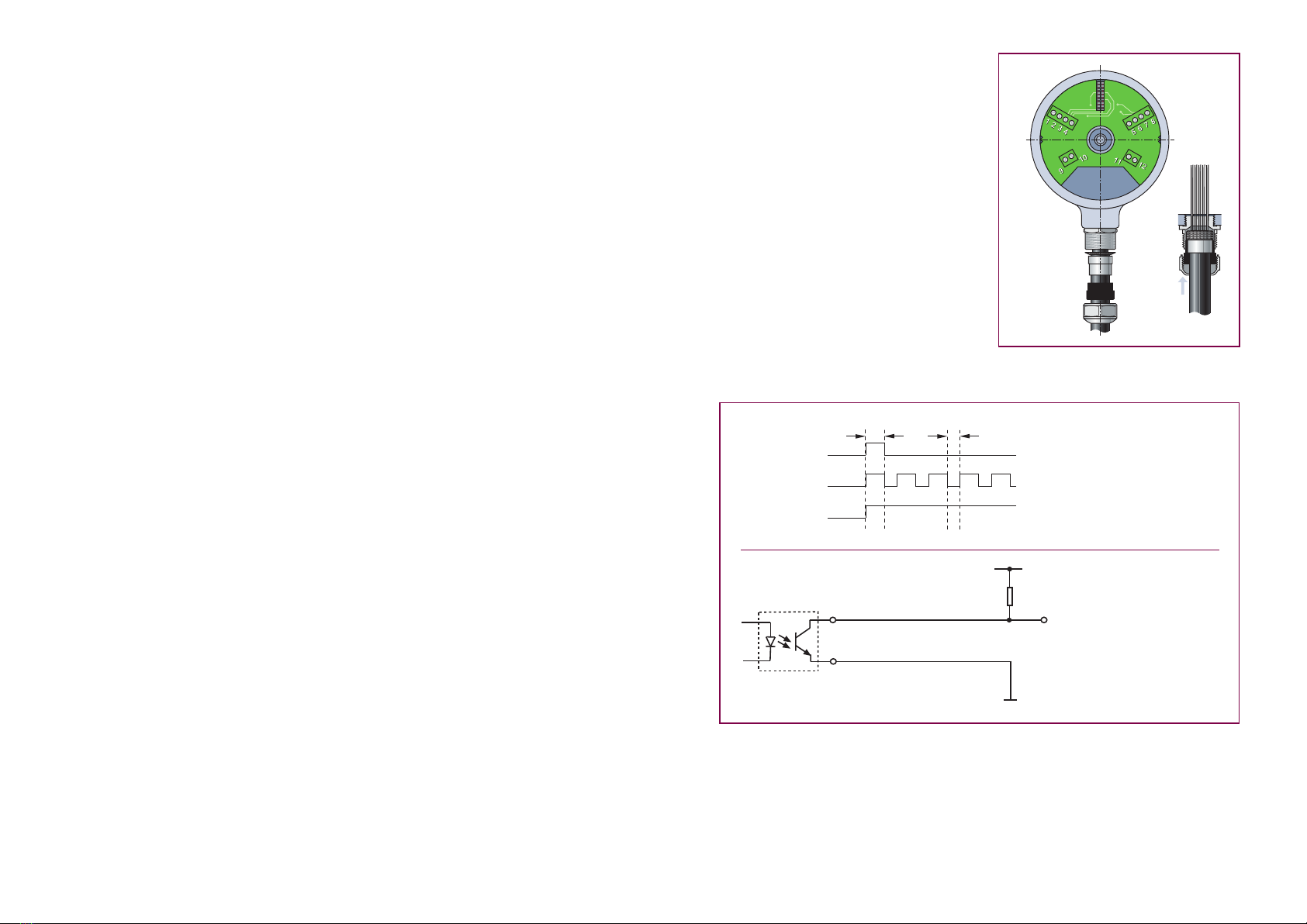
The main control system receives a message from the encoder about a
detected fault function via a signal at the encoder’s alarm output. This alarm
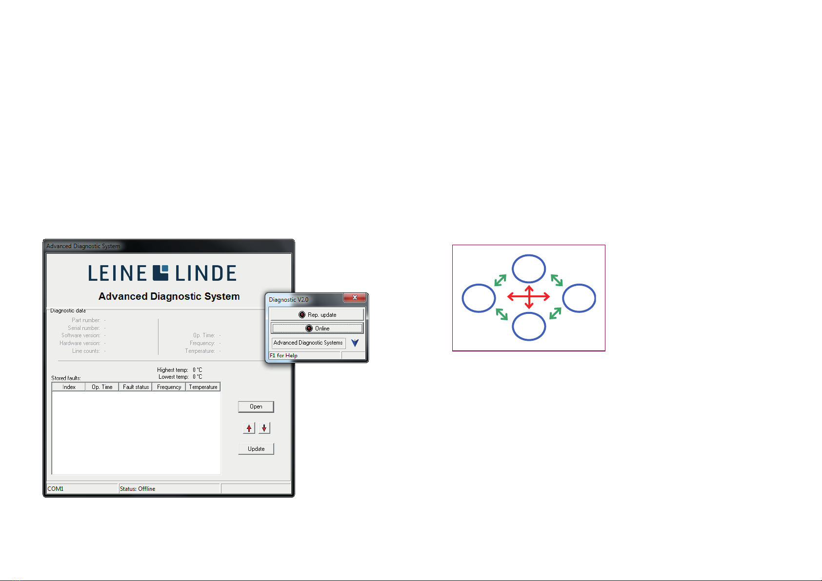
signal is sent to the operator who, with the help of a PC and the analysis
software of the diagnostic system, can communicate with the encoder and
establish the cause of the indicated fault. The operator is also informed of
the frequency, internal temperature and operating period at the time of the
fault. External faults can also be detected. The internal signals in the encoder
are compared with the signal that is generated in the cable. It is possible in
this way, for example, to detect an overload of the output signals from the
encoder. The analysis software can also be used to obtain information about
the total operating time and the max./min. operating temperature.
INSTALLATION OF ENCODER
Important!! When the cover of the encoder is removed, and if there is a risk
that you will come into contact with the electronics, or in conjunction with
the connection of cables, a grounding wrist strap or similar must be worn
in order to equalize the potential and to protect the encoder in this way
against ESD discharges which may damage the encoder.
Incremental encoders of model 861 are designed for assembly directly on the
drive shaft with a torque arm to prevent rotation of the encoder. This permits
simple and rapid assembly and makes the encoder insensitive to axial move-
ment of the drive shaft.
There are two alternative shaft diameters for the encoders: Ø 12 mm or
Ø 16 mm. The encoder is insulated from the drive shaft in order to prevent
currents from finding their way out from the drive shaft through the encoder
with resulting damage to the bearings in both the motor and the encoder.
The drive shafts must be made in accordance with Figure A, and it is im-
portant for the radial run-out on the drive shaft to be minimized, since a
radial run-out on the shaft gives an angular error from the encoder and
causes vibrations which can reduce the service life of the encoder.
M8-thread for disassembly
Figure B
Figure A
Assembly
The encoder is passed onto the drive shaft and is secured by pressing the
front edge of the hollow shaft with an o-ring against the abutment on the
drive shaft when the retaining screw is tightened; see Figure B.
The torque arm can be fitted
in various ways, and there are
holes with an M5 thread on
both the rear and the front
end of the encoder. It is also
possible to have an extra
torque arm angle with an M6
thread fitted to the encoder.
Account should be taken of
the fact that the mechanical
angular error reduces if a
torque arm is fitted perpen-
dicular to the centre of the
encoder and with the greatest
possible distance from the
centre.
The formula for calculating the mechanical angular error is:
Δρmek = ± 90 /π × K/R, where K is the radial run-out of the encoder and R is
the distance between the torque arm bracket and the centre of the encoder;
see Figure C.
Figure C
2 3