MSG Equipment MS604 User manual

USER MANUAL
MSG MS604
TEST BENCH FOR DIAGNOSTICS OF POWER
STEERING PUMPS
2017.05.17
QUALITY UNIQUENESS
INNOVATION TRAININGSERVICE
WARRANTY


3
1. DESCRIPTION ........................................................................................................................................................4
2. TECHNICAL CHARACTERISTICS.........................................................................................................................5
3. CONTROL UNITS...................................................................................................................................................6
4. SETTING INTO OPERATION................................................................................................................................9
4.1 Receipt and Inspection............................................................................................................................9
4.2 Connection...................................................................................................................................................9
4.3 Safety Measures.........................................................................................................................................9
4.4 Preventive Measures................................................................................................................................10
5. STEP-BY-STEP INSTRUCTION...........................................................................................................................10
6. ELECTRONICS MODULE DISMOUNTING .........................................................................................................12
6.1 Step-by-Step Instruction when Dismounting Electronics Module..............................................12
7. TEST CERTIFICATE ...............................................................................................................................................14
APPENDIX....................................................................................................................................................................15
CONTENTS

4
1. DESCRIPTION
Test Bench MS604 is used to test single- and double-circuit pumps with mechanical drive. The
equipment measures flow and pressure parameters under different speed. Besides, the bench
detects such faults as leak, roar, body wear out, reducing valve sticking. It is an equipment of
general service, used for work with power steering pumps of all types.
The key features of the bench are easy operation and reliability.
The bench body is made of polymer coating metal with table top of stainless steel.
User Manual - Test bench MSG MS604

5
User Manual - Test bench MSG MS604
2. TECHNICAL CHARACTERISTICS
Technical characteristics
Supply voltage, V 380
Supply type Three-phase
Dimensions, mm 1700*1100*850
Weight, kg 170
Driving power, kW 5.5
Drive rotation, rpm 0-1500
Selection of drive rotation direction Yes
Drive rotation adjustment Yes
Flowmeter, l/min 0-19
Manometer, bar 0-250
Adjustment range of pressure, bar 0-250
Fluid thermometer, °C 0-80
Tank capacity, l 22
Power fluid ATF DEXRON III
Power Steering Pump Testing
Measuring of maximum fluid pressure,
produced by a pump, bar 250
Measuring of maximum fluid flow, produced
by a pump, l/min 19
Measured parameters - Pressure
- Flow
Detected failures and parameters
- Leak
- Roar
- Performance
- Reducing valve sticking
Pump load Simulation of a steering rack in end
position

6
1 –Circuit I flowmeter; 2– Circuit I manometer; 3– PRESSURE REGULATOR CIRCUIT I; 4– PRESSURE
REGULATOR CIRCUIT II; 5 – Circuit II manometer; 6– Circuit II flowmeter; 7– Drive control display;
8– Drive rotation adjustment knob; 9– Load switch VALVE CIRCUIT II; 10 – Jaw chuck protection;
11 – HIGH PRESSURE CIRCUIT II fitting; 12 – Pump fittings; 13 – EMERGENCY BUTTON; 14 – Circuit
I delivery switch; 15 – Circuit II delivery switch; 16 – LOW PRESSURE CIRCUIT II fitting; 17 – LOW
PRESSURE CIRCUIT I fitting; 18 – HIGH PRESSURE CIRCUIT I fitting; 19 – Jaw chuck; 20 – Load switch
VALVE CIRCUIT I; 21 – Level and thermometer sensor; 22 – Switch; 23 – Voltage relay, automatic
cutout.
3. CONTROL UNITS
User Manual - Test bench MSG MS604

7
1 –Circuit I flowmeter measures the fluid flow, generated by circuit I of a pump.
2– Circuit I manometer measures the pressure, generated by circuit I of a pump.
3– PRESSURE REGULATOR CIRCUIT I limits the maximum pressure in the circuit I of the bench
hydraulic system.
4– PRESSURE REGULATOR CIRCUIT II limits the maximum pressure in the circuit II of the bench
hydraulic system.
5 – Circuit II manometer measures the pressure, generated by circuit II of a pump.
6– Circuit II flowmeter measures the fluid flow, generated by circuit II of a pump.
7– Drive control display with a touch screen. With its help direction and speed of rotation is set.
The display shows drive rotation value at the moment. In case when the protection is not placed
or EMERGENCY BUTTON (13) is on, the display shows the corresponding notification.
8– Drive rotation adjustment knob is used for smooth drive rotation change of 50 rpm/min.
Depending on the direction of the adjustment knob rotation, the direction of jaw chuck rotation is
set. The drive stops by pressing the adjustment knob.
9– Load switch VALVE CIRCUIT II creates a load on circuit II of a pump, simulating efforts in hydraulic
part of car suspension.
10 – Jaw chuck protection in the process of operation covers the rotating jaw chuck to avoid injury.
11 –HIGH PRESSURE CIRCUIT II fitting is used to connect a high-pressure hose to power fluid output
from circuit II of a pump.
Fig. 1 – Control panel
User Manual - Test bench MSG MS604

8
12 – Pump fittings are used to fix the steering pump on the test bench.
13 – EMERGENCY BUTTON turns off the bench totally, it is used in case of emergency.
14 – Circuit I delivery switch switches on/off power fluid supply from the bench tank to the input
of circuit I of a pump.
15 – Circuit II delivery switch switches on/off power fluid supply from the bench tank to the input
of circuit II of a pump.
16 –LOW PRESSURE CIRCUIT II fitting is used to connect a low-pressure hose of power fluid supply
to circuit II of a pump.
17 – LOW PRESSURE CIRCUIT I fitting is used to connect a low-pressure hose of power fluid supply
to circuit I of a pump.
18 – HIGH PRESSURE CIRCUIT I fitting is used to connect a high-pressure hose of power fluid
supply to the output circuit I of a pump.
19 – Jaw chuck is used to fix pulley or shaft and transmit engine torque from the bench drive to
the rotor part of a pump.
20 – Load switch VALVE CIRCUIT I creates a load on circuit I of a pump, simulating end position of a
steering rack.
21 – Level and thermometer sensor indicates temperature and level of power fluid in the tank.
22 – Switch activates the bench.
23.1 – Automatic cutout provides power supply to the bench and protects it from overpressure.
23.2 – Voltage relay is used to protect the bench from power supply interruptions.
Fig. 2 – Control display Fig. 3 – Automatic cutout, voltage relay
User Manual - Test bench MSG MS604

9
4.1 R I
4. SETTING INTO OPERATION
Check the set received. It must contain:
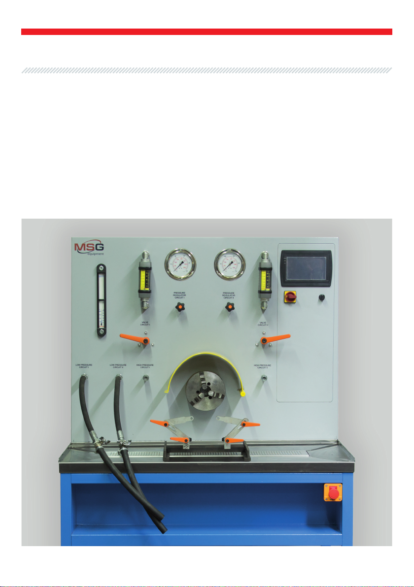
• test bench
• cables for connection to power supply
• 2 high-pressure hoses L-1.2 m
• 2 low-pressure hoses L-1 m
• set of fittings MS00555
• set of outside jaws and a jaw chuck key
• adapter for pump hubs
• User Manual.
Inspect the test bench for existence of damage. If it is found, please contact either the manufac-
turer or trade representative before launching the equipment.
WARNING! In case of obvious damage, use of equipment is forbidden.
4.2 C
4.3 S M
Install the bench in the premises with <90% humidity and temperature of 0-40°C. Make sure that
there is permanently no condensate on the bench.
Connect the test bench to 380 V (3L+N+Pe) three-phase alternating current.
WARNING! Work with unearthed device is strictly forbidden. Use socket of 3L+N+Pe type
(three contacts per phase, one zero and one earth contact), observe forward sequence of phases).
Fill in the tank through the filler neck with ATF oil for power steering gears up to 21 level.
WARNING! Use a new ATF oil only to avoid failures in operation of the test bench and tested
units.
It is strongly recommended to learn actual User Manual before launching the bench. Work with high-
pressure hydraulic equipment without learning safety measures instruction is strictly forbidden.
Tightening or unscrewing nuts in high-pressure hoses in the process of operation of the tester is
forbidden.
Removal of quick disconnect coupling in the process of operation of the tester is forbidden.
Usage of defective high-pressure hoses is forbidden.
Work with the tester must be carried out in rubber gloves.
In case of skin contact with power fluid, wash the place of impact with a soap.
WARNING! Power supply voltage must correspond to the technical characteristics of the
test bench.
User Manual - Test bench MSG MS604

10
4.4 P M
Operation of a tested pump without fluid is forbidden.
Replace the filter cartridge timely (annually or in case of contamination). The filter is placed on the
top of the tank.
Control the sealing of hydraulic system.
Keep the bench clean.
5. STEPBYSTEP INSTRUCTION
Proceed to diagnostics of a single-circuit pump. Diagnostics of a double-circuit pump is made on
each circuit.
WARNING! Control fluid level in the tank with 21 sensor to prevent a pump from starvation.
Fig. 4 – Filler neck and filter
WARNING! Make sure that the unit is not damaged before its testing. Make sure that
all fittings are tightened and the unit is safely fixed on the bench.
WARNING! The pump circuit, responsible for car suspension, does not have a reducing valve
in its body, it may cause overload of the system. Adjust maximum pressure with pressure regulator.
•Switch on the automatic cutout (23.1) which is placed on the left side panel (see Fig.3).
•Turn on the switch (22) to activate the control display (7), it means that the bench is ready for
operation.
•Fix a drive pulley or a pump shaft in the jaw chuck (19).
•Fix a pump in the fitting (12).
•Connect the bench to a pump (Fig. 5).
•Place the jaw chuck protection (10).
User Manual - Test bench MSG MS604

11
• Open circuit I delivery switch (14) and wait until the fluid fills a pump by gravity.
• Start a pump drive on pressing the button with the needed rotation value on the display (7).
Or set the needed rotation, while rotating drive rotation adjustment knob (8).
• Measure pressure and fluid flow parameters, generated by a pump.
• With a smooth turn of the load switch VALVE CIRCUIT I (20), check productivity of a pump under
load.
• Pressure, generated by a pump, is measured by Circuit I manometer (2).
• Fluid flow, generated by a pump, is measured by Circuit I flowmeter (1).
• Stop a pump drive by pressing STOP button on the display (7).
• EMERGENCY BUTTON deactivates the bench totally in case of emergency.
• Disconnect a pump from the bench.
• On finishing the testing, deactivate the stand with a switch (22).
• Switch off the automatic cutout (23.1) on finishing the work with the bench.
1 –LOW PRESSURE CIRCUIT I fitting; 2 –HIGH PRESSURE CIRCUIT I fitting;
3 –Pump input; 4 –Pump output.
Fig. 5 – Connection of power steering pump to the bench
User Manual - Test bench MSG MS604

12
User Manual - Test bench MSG MS604
6. ELECTRONICS MODULE DISMOUNTING
In case of failure of the bench electronics module, it is necessary to dismount the electronics module
and sent it to the manufacturer or trade representative in order to get a warranty maintenance.
WARNING! Do not open the electronics module. If the seal is damaged, warranty is no longer
valid.
6.1 STEPBYSTEP INSTRUCTION WHEN DISMOUNTING
ELECTRONICS MODULE
• Dismount the back panel of the bench.
• Disconnect 7and 8sealed connectors in the lower side of the electronics module.
Fig. 6 – Electronics module connectors
• Remove the electric motor terminal box cover and disconnect 4, 5, 6wires.
Fig. 7 – Electric motor terminal box cover

13
User Manual - Test bench MSG MS604
• Disconnect 1, 2, 3wires from the electromagnetic contactor.
• Unscrew 8 nuts on perimeter of the electromagnetic contactor and dismount it.
Fig. 8 – Electromagnetic contactor
Mounting of the module is carried out in reverse sequence.
Fig. 9 – Electronics module

14
User Manual - Test bench MSG MS604
7. TEST CERTIFICATE
Test Bench MSG MS604 for diagnostics of power steering pumps meets technical requirements of
Directive 2014/30/EU - Electromagnetic Compatibility (EMC) EN Directive 2014/35/EU - Low voltage
(LVD) Directive 2006/42/EC - Machinery (MD) and is qualified for exploitation.

Load generation
(steering rack
simulation in extreme
position)
Meter indication
Roar Leak Defect
Fluid flow Fluid pressure
No Nominal, set by the
manufacturer Minimum No No No
No Lower than set by the
manufacturer Minimum No No
Deformation of sealing
plate tearing of pump
working section
No Nominal, set by the
manufacturer Indicator changes after
each load generation No No
Wear out of operating
steam (rotor with
blades and working
chamber). Wear out of
bearing
Yes Minimum Lower than set by the
manufacturer No No
Wear out of operating
steam (rotor with
blades and working
chamber). Deformation
of sealing plate tearing
of pump working
section
Cyclic Indicator changes after
each load generation
Indicator changes after
each load generation No No
Loss of bypass valve
mobility, wear out of
valve seat
Yes/No No No No No Loss of bypass
valve mobility
Yes/No _ _ _ Yes Wear out of seals,
gaskets
Diagnostics Indicators of Power Steering Pumps
APPENDIX
15
User Manual - Test bench MSG MS604

Table of contents
Other MSG Equipment Diagnostic Equipment manuals