Ref Qte Description
1 1 Motor unit (A)
2 1 Motor unit (B)
3 1 Main crossbar
4 1 Cross actuation centre bar
5 2 Cross actuation insert bars
6 1 Engagement tool
7 2 Aluminium chassis clamp plates (set)
8 4 Bolt - M10x60
9 2 Chassis U plate
10 1 Instruction manual
11 1 Convoluted cable trunking
14 1 Positive (+) red battery cable 1.8m including fuse
holder & 100A fuse
15 1 Negative (-) black battery cable 1.6m
16 8 Bolt - M10x50
17 12 Nylon nut M10
18 12 Washer 10mm Ø
19 20 Screw - M4x15
20 10 Cable trunking P-clips 19.2mm
21 10 Cable P-clips 10.4mm
22 4 Battery terminal connector 8mm Ø
23 2 Battery terminal connector 6mm Ø
24 4 Spade fork connector
25 3 Cable number markers (1,2,3,4)
26 3 Cable polarity markers (+, -)
27 4 Motor unit cable ties 8x400
28 10 Cable ties 2x70
29 1 Battery isolation switch, cover & key
30 2 Roller distance spacers 20x20
31 1 Remote control handset with lanyard
32 1 Electronic control unit
33 2 Rubber isolation shell for battery isolation switch
34 2 Screw – M5x40
TABLE OF CONTENTS
Package contents (parts list)
Declaration of Conformity
Introduction
Intended use
Specifications
Installation - safety guidelines
Installation - mechanical components
Installation - electrical/electronic components
Operation - safety guidelines
Operation - motor units
Operation - remote control handset
Operation - electronic control unit
Operation - getting started
Operation - hitching and unhitching
Maintenance
Trouble-shooting
Guarantee
EC DECLARATION OF CONFORMITY
Product: Manoeuvring Device for Caravans
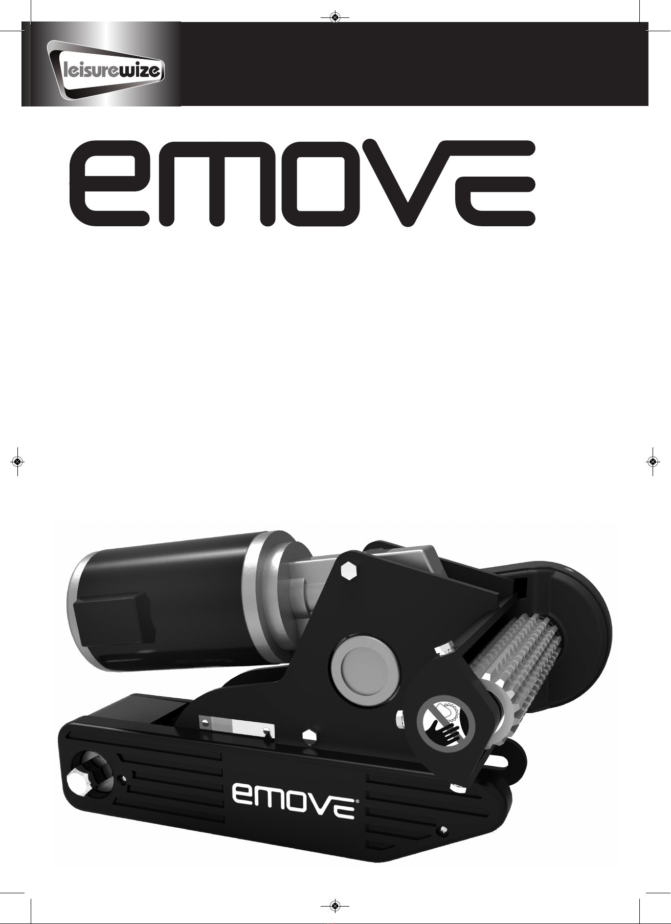
Model No: EM203
Manufacturer: The Ace Supply Company Ltd T/A Streetwize Accessories, Unit 1, Royce Trading Estate,
Ashburton Road West, Trafford Park, Manchester M17 IRY
EU Authorized Representative : Ace Supply Co (Europe) Ltd, 25 Herbert Place, Dublin 2. DO2 AO98 Republic of Ireland.
This declaration is issued under the sole responsibility of the manufacturer.
The object of the declaration described above is in conformity with the relevant EC Directives:
2014/53/EU RE Directive, 2014/30/EC EMC Directive, 2006/42/EC Machinery Directive, 2011/65/EU RoHS Directive, ECE-R10
Conformity is shown by compliance with the applicable requirements of the following standards:
EN IEC 62321-5:2013, EN IEC 62321-4:2013+A1:2017, EN IEC 62321-7-2:2017, EN IEC 62321-6:2015,
EN IEC 62321-8:2017, EN300 220-1:2017, EN300 220-2:2017, EN301 489-1:2017, EN301 489-3:2019, EN 62311: 2008,
EN ISO 12100:2010, ECE-R10.05
Technical Data
Remote Control Frequency Class 1 Frequency 868 MHz <20mA.
Operational Voltage 12v DC Current Consumption Average 20A maximum 100A.
Area of operation Single axle caravan with a total weight up 2250kg on hard/flat surfaces,
1800kg on other surfaces, 1450kg on 18% gradient.
Speed approx: 9cm per second
Weight approx: 37kg
Signed for and on behalf of: The Ace Supply Company Ltd T/A Streetwize Accessories
Place of Issue: Manchester
Date of Issue: 21/10/2020
Name: Lesley Cooper
Position: QC Manager Signature:
UK DECLARATION OF CONFORMITY
Product: Manoeuvring Device for Caravans
Model No: EM203
Manufacturer: The Ace Supply Company Ltd T/A Streetwize Accessories,
Address: Unit 1, Royce Trading Estate, Ashburton Road West, Trafford Park, Manchester M17 IRY
EU Authorized Representative : Ace Supply Co (Europe) Ltd, Address: 25 Herbert Place, Dublin 2. DO2 AO98 Republic of Ireland.
This declaration is issued under the sole responsibility of the manufacturer.
The object of the declaration described above is in conformity with the relevant UK Statutory Instruments (& their amendments):
2017 No. 1206 The Radio Equipment Regulations 2017, 2016 No. 1091 The Electromagnetic Compatibility Regulations 2016,
2008 No. 1597 The Supply of Machinery (Safety) Regulations 2008, 2012 No. 3032 The Restriction of the Use of Certain Hazardous
Substances in Electrical and Electronic, Equipment Regulations 2012, ECE-R10
References to the relevant designated standards in relation to which conformity is declared:
BS EN IEC 62321-5:2013, BS EN IEC 62321-4:2013+A1:2017, BS EN IEC 62321-7-2:2017, BS EN IEC 62321-6:2015, BS EN IEC
62321-8:2017, BS EN 62311:2008, EN300 220-1:2017, EN300 220-2:2017, EN301 489-1:2017, EN301 489-3:2019, BS EN ISO
12100:2010, ECE-R10.05
Technical Data
Remote Control Frequency Class 1 Frequency 868 MHz <20mA.
Operational Voltage 12v DC Current Consumption Average 20A maximum 100A.
Area of operation Single axle caravan with a total weight up 2250kg on hard/flat surfaces,
1800kg on other surfaces, 1450 on 18% gradient.
Speed approx: 9cm per second
Weight approx: 37kg
Signed for and on behalf of: The Ace Supply Company Ltd T/A Streetwize Accessories
Place of Issue: Manchester
Date of Issue: 21/10/2020
Name: Lesley Cooper
Position: QC Manager Signature:
PACKAGE CONTENTS (Parts list)