LEITAT 1 User manual

LEITAT 1
AUTOMATED RESUSCITATOR
USER GUIDE

2 | 14
LEITAT 1 | AUTOMATIC RESUSCITATOR | USER GUIDE
This project has been carried out by the following alliance of companies:
LEITAT
Consorcio de la Zona Franca
Hewlett-Packard
BSH Electrodomésticos España
Scientific leadership by Hospital Parc Taulí de Sabadell
Access to the online content:
•Explanatory video
•Instructions manual
•Data collection form
•FAQs
•Contacts
NOTE: Please address any questions or queries about this User Guide through the QR code.

3 | 14
LEITAT 1 | AUTOMATIC RESUSCITATOR | USER GUIDE
CONTENTS
1. INTRODUCTION 4
2. INSTALLATION AND SET UP 4
2.1. GENERAL INFORMATION 4
2.2. INDICATIONS OF USE6
2.3. ASSEMBLING OF THE SYSTEM 6
2.4. OPERATION OF THE CONTROL CONSOLE 7
3. WARNINGS OR PRECAUTIONS OF USE11
5.1. WARNINGS 12
5.1.3 | Responsibilities of the operator 12
5.1.4 | Maintenance 12
5.1.5 | Accessories 12
5.1.6 | Batteries 12
5.1.7 | Elimination 13
5.1.8 | Electrical safety 13
5.1.9 | Electromagnetic compatibility 13
5.2. PRECAUTIONS OF USE 13
5.2.1 | Installation 13
5.2.2 | Maintenance 14
5.2.3 | Cleaning, disinfection and sterilization 14

4 | 14
LEITAT 1 | AUTOMATIC RESUSCITATOR | USER GUIDE
1. INTRODUCTION
The mechanical ventilation system LEITAT 1 is a device designed to keep in vital support the
patient in a situation of severe respiratory failure who requires intubation and invasive mechanical
ventilation. It should not be considered as a partial ventilatory support system (non-invasive
mechanical ventilation - NIMV) in patients who ventilate spontaneously. It is not a therapy, it is a
support intervention, a medical device for ventilatory and temporary support therapy that
ventilates the patient while correcting the originating problem.
In its entirety, the device allows to apply a mandatory ventilation mode with a programmable
volume to a patient through the mechanical actuation of a conventional resuscitation balloon
system (AMBU).
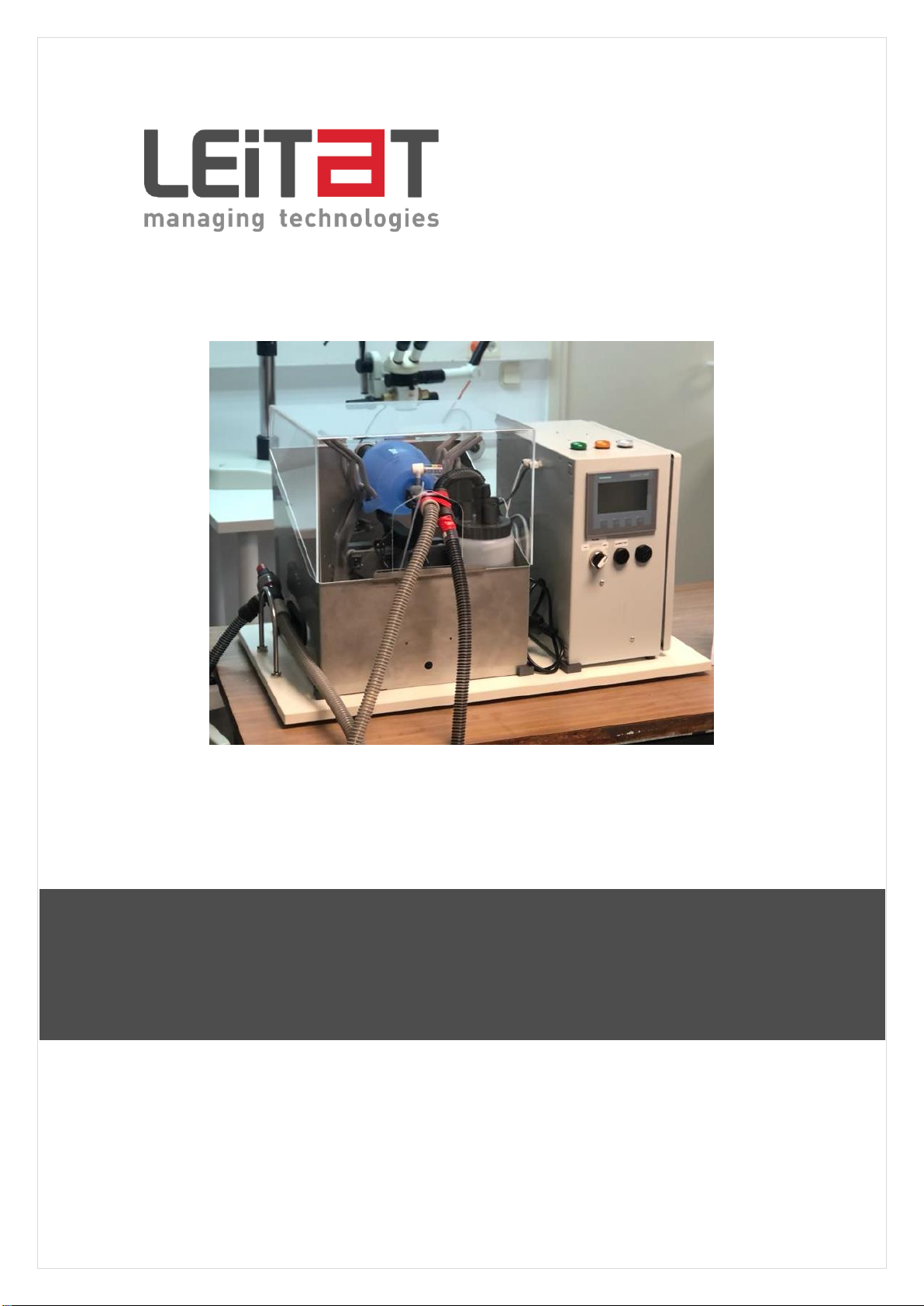
The use of this equipment is exclusively for clinical research and only in a hospital setting.
Figure 1: Illustration of the device
2. INSTALLATION AND SET UP
2.1. GENERAL INFORMATION
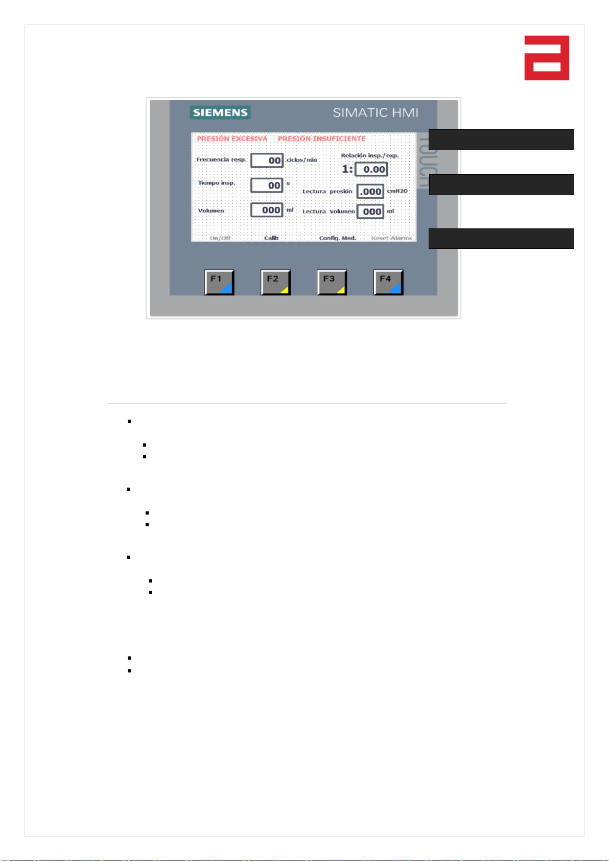
LEITAT 1 works as Volume-Controlled Ventilation and mode of operation is mandatory.
In each ventilation cycle, the inspiratory time (in seconds) can be adjusted, allowing the desired
inspiration: expiration (I: E) ratio to be selected.
In normal operating mode, the user can control the number of ventilatory cycles per minute
(respiratory rate), as well as the amount of air blown by controlling the actioning blades. In the
case of detecting a pressure greater than 50 cmH2O, an audible and lighted warning alarm is
activated and, automatically, the operating mode changes from "Volume-Controlled Mode” to
"Pressure-Controlled Mode", maintaining a breath cycle of 1 inspiration for 2 expiration but
applying a volume of air that does not exceed the pressure of 50 cmH2O.

5 | 14
LEITAT 1 | AUTOMATIC RESUSCITATOR | USER GUIDE
The technical specifications of the equipment are as follows:
MODULE DIMENSIONS
Width
800 mm
Height
450 mm
Depth
475 mm
Weight
15 kg
ELECTRICAL VALUES
Voltage
240 VAC (50Hz)
Power
100 VA
CLINICAL VALUES
Tidal volume
150 ml to 600 mL
Maximum flow (VMAX)
9 –18 L/min
Respiratory rate (rpm)
12 to 30 rpm
Inspiratory pressure
0 to 50 cmH2O
PEEP pressure
0 to 20 cmH2O
Inspiratory time
0.6 - 1.5 seconds
O2percentage
21% to 100%
PERMITTED BREATHING MODE
Mandatory
Yes
Spontaneous
No
TYPE OF PERMITTED VENTILATION
Non-invasive (NIV)
Not designed for it
Invasive (INV)
Yes
Table 1. LEITAT 1 technical specifications
POWER SUPPLY
The equipment has a 2m grounded Schuko IEC power cable that connects at one end to the rear
base of the appliance, equipped with a 1.5A fuse protection; and on the other hand, to a 220-
240V power outlet at the facilities.
CONTROL CONSOLE
The equipment has an area with a start and stop switch, some parameterization buttons and a
parameter indicator display. The parameters configurable by authorized medical personnel are
the inspiration volume, the inspiration time and the respiratory rate.

6 | 14
LEITAT 1 | AUTOMATIC RESUSCITATOR | USER GUIDE
CONFIGURABLE PARAMETERS
Inspiratory volume: 150 –600 cm³
Inspiratory time: 0,6 –1,5 s
Inspiratory rate: 12 –30 rpm
Positive end-expiratory pressure (PEEP): 0 - 20 cmH2O
MONITORING AND ALARM
The equipment has various sensors that monitor its operation, supervising parameters such as
volume, pressure, times and other algorithms that allow detecting any anomaly.
In summary, the monitored alarms are as follows:
•Volumetric deviation
•Maximum pressure, greater than 50 cmH2O
•Pressure less than 15 cmH2O
•Deviation of respiratory rate
•Mechanical failure
•Power supply failure
All alarms are manifested visually and through the piezoelectric buzzer.
2.2. INDICATIONS OF USE
The most important factor when making any decision is the continuous observation of the patient
and his/her evolutionary trend. Therefore, the indication to intubate or ventilate a patient is
generally a clinical decision based more on the signs of respiratory distress than on parameters
of gas exchange or pulmonary mechanics, which are only indicative.
Selection criteria:
COVID19 patients who have ARDS in severe phase and who cannot be treated with
conventional mechanical respirators due to high demand and lack of availability.
2.3. ASSEMBLING OF THE SYSTEM
Needed equipment for mechanical ventilation:

7 | 14
LEITAT 1 | AUTOMATIC RESUSCITATOR | USER GUIDE
For the intubation
Endotracheal tube (TET): the size depends on the age and the route of entry (mouth,
nose). It features a balloon in adults and some pediatric.
Intubation introducers.
Laryngoscope with blades of different sizes and curvatures.
Maguill’s clamp.
Syringe to blow the balloon.
Tube fixing system (for instance: Haid).
Support equipment
AMBU with reservoir and connection to flowmeter.
Two O2 sources: One for the ventilator and one for the ambu.
Aspiration equipment (sterile) and aspirator.
Guedel cannula.
Ball pressure gauge: inflatable to measure its pressure.
220-240V power socket
Assembling
Inspiratory part: tube from ventilator (end of resuscitative balloon) to patient, with
intermediate connection to a unidirectional valve through its inhalation end.
Expiratory part: from unidirectional valve (exhalatory end) -with option to ambient air
(PEEP 0) or with connection to the tube- to container with water column to generatePEEP
from 0 to 20 cm.
oWarning: to be used only with distilled water to avoid the growth of bacteria.
High-efficiency filter placed between bidirectional valve and patient.
Tube with connection to resuscitative balloon and flowmeter for oxygen administration.
Once the assembly is finished, to start the equipment, please check that the alarm switch is OFF
so that it does not sound when it detects that there is no current.
The battery level of the equipment should also be checked every time it is started. To do this,
once the equipment is turned on, please set the alarm ON and verify that it works with "Test
Alarm".
2.4. OPERATION OF THE CONTROL CONSOLE
The HMI (initials of Human-Machine Interface) is the graphical control panel through which the
device operator can control the ventilation process, through the following screens:
1 | MAIN SCREEN
Screen to be used by the clinical professionals:
F1: start / stop the cycle
F2: calibration screen
F3: medical configuration screen
F4: alarm reset

8 | 14
LEITAT 1 | AUTOMATIC RESUSCITATOR | USER GUIDE
On this screen the operator can enter values in the control parameters, as well as monitor
the pressure and volume values that the system is registering.
Control parameters
Respiratory rate: number of respiratory cycles per minute.
Min value: 12 cycles/min
Max value: 30 cycles/min
Respiratory time: time interval that the inspiration movement lasts.
Min value: 0.6 seconds
Max value: 1.5 seconds
Delivering volume:
Min value: 150 ml
Max value: 600 ml
Monitoring values
Pressure reading, in centimetres of water (cmH2O)
Volume reading, in millilitres (ml)
Once the control parameters have been entered, the user must press the F1 (On / Off) key
to start the process.
ALARM AREA
CONTROL AREA
FUNCTION KEY AREA

9 | 14
LEITAT 1 | AUTOMATIC RESUSCITATOR | USER GUIDE
2 | CALIBRATION SCREEN
This is the screen that is used to calibrate the system before released from the factory. A
priori, the user does not have to use it, only in case of problems with the equipment, for
example, if the machine starts delivering irregularly the air specified on the screen. In this
case, it must be re-calibrated.
Calibration process
Hold down the Open button to reach the desired value which will be later introduced in “Open
position”.
1 | Enter open position value: position that determines when the actuator touches the
balloon without pressing it.
2 | Hold down the Close button to move the actuator until the desired value is reached to
be later introduced in “Close Position”.
3 | Enter close position value: position the actuator reaches when it presses the balloon to
generate inspiration.
4 | Important: the Open and Close buttons which move the actuator do not work when the
system is working automatically (ie., when it has been started with the F1 On / Off key).
5 | Bring the actuator from Open position to Close position with the Close button and
observe the delivered volume.
6 | The volume reading will be shown in the monitoring value “Volume reading”.

10 | 14
LEITAT 1 | AUTOMATIC RESUSCITATOR | USER GUIDE
7 | When verifying that the movement delivers the desired volume, please press the Save
button and these positions will be calibrated to deliver that air volume.
8 | Between verification and verification, you may reset the volume reading value with the
“Volume Reset” button.
9 | In this screen, the F3 key “Delete all”will delete all the saved calibration values.
3 | MEDICAL CONFIGURATION SCREEN
This is the screen where medical personnel can configure internal parameters on the
operation of the machine:
Tolerance between the specified air and the delivered air (%). Between 0 and 15%.
Correction on total volume when there is a discrepancy between the specified and
delivered volume (%).
Number of times there has been a discrepancy between volumes before reporting.
Number of times there has been a discrepancy to trigger an alarm.
Tolerance between the specified cycle duration and the actual duration (%).
4 | MOTOR SET-UP SCREEN
Through this screen the user can set up system parameters, such as alarm thresholds, speed
ranges and actuator acceleration.
Important: The displayed and editable values in this screen should not be modified during the
normal operation of the device. A trained technician may modify such values when needed
while adjustment, commissioning or maintenance operations.

11 | 14
LEITAT 1 | AUTOMATIC RESUSCITATOR | USER GUIDE
This screen will be used during the manufacturing process to characterize the system at the
electromechanical level. The following parameters can be modified:
Acceleration: Acceleration value when moving the actuator.
Deceleration: Acceleration value when braking the actuator.
Max. velocity: Configurable maximum speed value in the actuator movement.
Min. velocity.: Configurable minimum speed value in the actuator movement.
3. WARNIGNS OR PRECAUTIONS OF USE
The objective of this section is to collect information regarding the risks resulting from the incorrect
use of the automated resuscitator.
Three levels of information are established according to their degree of criticality.
-Warnings: They indicate conditions that may result in risks for the patient or for the
operator.
-Precautions: They indicate conditions that may affect or damage the equipment or its
accessories.
-Additional Information: They collect complementary information, which help in
understanding the operation of the equipment.

12 | 14
LEITAT 1 | AUTOMATIC RESUSCITATOR | USER GUIDE
5.1. WARNINGS
The following information shows the conditions that may cause a risk to the safety of the patient
and / or operator.
The mechanized ventilation system LEITAT 1 is a temporary aid to the ventilatory function of the
inspiratory muscles. It is not a therapy, it is a support intervention, an equipment which aims to
provide ventilatory and temporary support that ventilates the patient while correcting the
originating problem.
5.1.3 | Responsibilities of the operator
Before using the automated resuscitator, this manual should be read and fully understood. The
use of the equipment before the full understanding of its characteristics and functions may result
in risky conditions for the patient, the operator and the equipment itself.
After reading and understanding this manual, it should be kept in an accessible place for quick
reference if necessary.
This automated resuscitator should ALWAYS be used in accordance with the specifications
contained in this manual.
This equipment should be handled and operated only by properly trained professionals.
Automated resuscitator alarms indicate a hazardous situation, requiring operator attention and
should NEVER be ignored.
5.1.4 | Maintenance
This automated resuscitator is a life support equipment. In the event of any problem or
malfunction with the use or operation of the equipment, it MUST be replaced by another while
its operation is supervised at all times.
For cleaning the equipment, the same cleaning protocols established in the hospital will be
applied for cleaning medical equipment in the intensive care unit.
The pressure regulator (PEEP) bottle should only be filled with distilled water to avoid bacteria
generation problems.
5.1.5 | Accessories
Always use accessories, parts and original equipment parts. Modification or replacement by
non-original parts may cause this equipment to malfunction. Furthermore, failure to comply with
this point could put the safety of the patient and the operator at risk.
5.1.6 | Batteries
The automated resuscitator alarm system has a battery so that, in case of failure of the electrical
power system, it ensures its operation for at least 20 minutes. Verify when starting up the
equipment that the battery is not exhausted, turning the alarm ON and pressing the "Test Alarm"
button to verify that it works. In case of low battery detection of the alarm system, it should be

13 | 14
LEITAT 1 | AUTOMATIC RESUSCITATOR | USER GUIDE
replaced immediately, supervising the equipment at all times between detection until the battery
is replaced.
If the alarm system battery needs to be replaced, it must be replaced by one with identical
characteristics. Replacing the battery with one of different characteristics could lead to improper
operation of the alarm system.
5.1.7 | Elimination
All replaced parts and pieces must be disposed of as determined by the local legislation where
the equipment is installed.
Special attention should be paid to the battery of the alarm system, and electronic components,
which must be treated as special waste and disposed of independently from the rest of the
equipment as they can present a risk to the environment.
5.1.8 | Electrical safety
ALWAYS use an AC power supply that provides a grounding pin connection.
Never disassemble the box containing the electrical system of the automated resuscitator. This
operation presents a risk of electric shock.
Theleakage current measuredin theequipmentis less than 0.5 µA, so there isno risk of causing
untimely trips of the differentials due to the accumulation of equipment.
5.1.9 | Electromagnetic compatibility
The use of this equipment requires special precautions regarding its electromagnetic
compatibility.
Only connect this equipment to a grounded electrical outlet.
Never disconnect the grounding cable from the equipment.
The equipment must be used only in a hospital setting.
Use restrictions:
Radio frequency equipment, such as mobile, table, or portable devices, may interfere with the
operation of the automated resuscitator.
5.2. PRECAUTIONS
The following are conditions that may affect or damage the equipment or its accessories.
5.2.1 | Installation
When in operation, this automated resuscitator:
NEVER be covered or placed in such a way that it blocks your access or covers the
ventilation openings. These entrances are located on the sides of the team.

14 | 14
LEITAT 1 | AUTOMATIC RESUSCITATOR | USER GUIDE
NEVER place this equipment exposed directly to heat sources or in places where it can
get wet or splashed.
Place this equipment on a firm, level surface.
5.2.2 | Maintenance
To ensure the correct operation of the equipment, the following actions must be carried out:
Initial verification Check List:
Carry out a verification of the general condition of the equipment, as well as aspects of
cleaning, assembly and connections with an electrical power source.
It is recommended to be done daily or before use.
Functional Verification Test –PVF:
Perform the functional verification of the equipment, as well as the operation of the alarm
and monitoring resources, by means of fault simulations, using a pulmonary simulator.
It is recommended to perform before the use of the equipment in a patient or when there are
doubts about the operation of the equipment.
5.2.3 | Cleaning, disinfection and sterilization
Never immerse the equipment in liquid solution, nor allow liquids to enter its internal part.
Never use abrasives on the surface of the automated resuscitator, especially on your screen.
Table of contents
Popular Medical Equipment manuals by other brands

Maquet
Maquet Betastar 1131 Maintenance & Repair Instructions

Zeiss
Zeiss S7 / OPMI VISU 160 Instructions for use

MHC Medical Products
MHC Medical Products SureLife Clearwave II user manual

Eko Devices
Eko Devices CORE quick start guide

Nasco
Nasco Life/form LF00890U instruction manual

Arjo
Arjo Dual-Loop Attachment Straps Instructions for use