EN-5
PREFACE
This Operator’s Manual is meant for personnel who operate the ma-
chine and are responsible for its daily maintenance.
Kindly read this entire manual prior to starting work.
Instructions relating to your safety and/or that of others are
marked in the margin by a warning triangle containing an ex-
clamation mark. Always observe these instructions with par-
ticular care and attention.
Instructions which may lead to serious material damage in
case of non-compliance or incorrect use are indicated in the
margin with an exclamation mark.
The machine described in this manual may contain components
which do not form part of the standard equipment but are available
as optional extras.
This is not indicated in all cases since standard specifications may dif-
fer from country to country.
Furthermore, machines and optional extras may be adapted to spe-
cific regional conditions and are also subject to permanent research
and innovation.
For this reason, the specifications of your machine may not be con-
sistent with the pictures in this manual.
WARRANTY CONDITIONS
For those parts which fail under normal operating conditions, the
factory will make replacement parts available, free of charge, for a
period of 12 (twelve) months from the date of purchase.
The warranty shall not apply if the instructions mentioned in this
manual have not been followed, or if they have not been followed
completely or correctly.
Nor will the warranty apply if you or third parties modify the ma-
chine without our foreknowledge and/or authorisation.
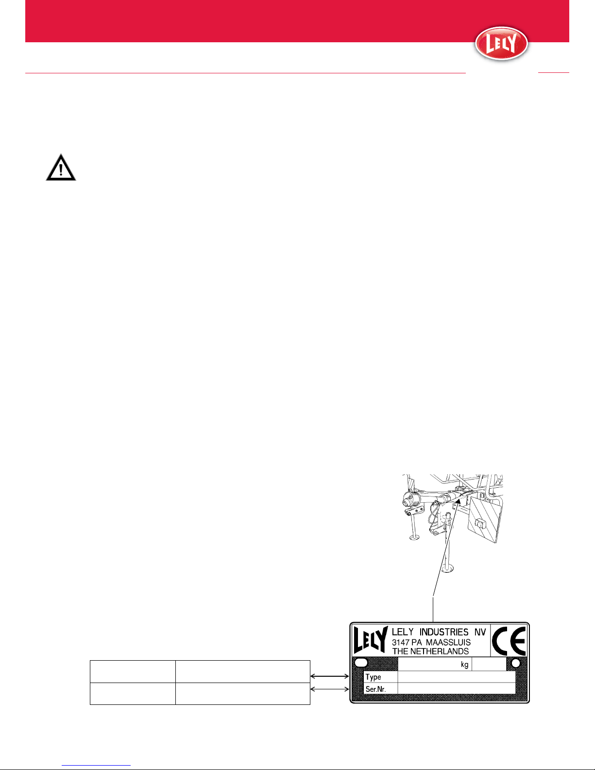
TYPE AND SERIAL NUMBER OF YOUR MA-
CHINE
The type/serial number plate is fitted to the front of the machine on
the fixation plate for the safety panel support.
Please specify the type and serial number of your machine in any cor-
respondence and when ordering spare parts.
Complete the box below with these numbers.