Lemco Micro line MLF-301 User manual


2
1. IMPORTANT SAFETY PRECAUTIONS INFORMATION
READ THE FOLLOWING WARNINGS BEFORE YOU USE YOUR DEVICE
Παρακαλούμε φυλάξτε αυτό το εγχειρίδιο σε ασφαλές μέρος για μελλοντική αναφορά.
Power supply / Mains cord
zx w Operate the unit only within the voltage range defined as appropriate by the man-
ufacturer.
zx w Occasionally check the power connector and remove dirt or dust that may have
accumulated.
zx w Use only the mains cord that comes with your unit.
zx w Do not operate the unit or plug in the mains cord if it is broken, split, or damaged
in any way.
zx w Do not place the mains cord next to heating devices. Do not pull it, place heavy
objects on it or damage it in any way. Keep it out of reach of children.
zx w Ensure that the device is plugged in a properly grounded socket. Insufficient
grounding may cause electrocution.
zx w Always carefully disconnect all plugs by pulling on the plug and not on the cord.
Make sure the unit's power switch is turned off before removing the cord from an
outlet.
zx w Disconnect the mains cord when the unit is not in use for long periods of time or
during storms.
zx w Do not connect the unit to a multiple-outlet to avoid plug overheating.
Disassembling
zx w This unit contains parts that cannot be repaired by the user. Do not disassemble
or try to repair it as this will void all warranties. Please contact the manufacturer if
you experience any problems with your unit.
Water/humidity
zx w Do not keep the unit in a humid place or near water.
zx w Do not plug/unplug the unit with wet hands.
WARNING
The following safety precautions must be observed to prevent fire
or electric shock hazard. Safety precautions include but are not re-
stricted to the following:

3
Fire
zx w Never place a candle or another source of fire on the unit as it may fall and start
a fire.
zx w If the mains cord or the power connector is damaged or destroyed, or if there is a
sudden loss of picture during operation, or if you notice a strange smell or there is
smoke, immediately switch the unit off, disconnect the mains cord and contact the
manufacturer’s technical support department.
Installation / Storage
zx w This unit contains high precision pieces of electronics. To ensure optimal perform-
ance and avoid damage, do not store it in any location where it may collect dirt,
duct, lint, etc. Do not expose it to extreme heat or cold (e.g. in direct sunlight, near
a heater or in the car during the day). Place the unit in a secure place to avoid falls.
zx w Before moving the unit, always unplug all cords first.
zx w When installing the unit, make sure that an outlet is within easy reach. In case of
malfunction, switch the unit off and unplug the power cord. When the unit is not in
use for a long period of time, make sure that the mains cord is disconnected.
Connectivity
zx w Before connecting the unit to other electronic devices, always switch off and unplug
all devices.
Maintenance
zx w Do not spill liquids on the unit. Do not use any diluents or volatile liquid to clean
the unit. Instead, use a soft slightly damp cloth and allow the unit to dry completely
before using again.
Handling
zx w Do not poke your finger into the openings on your unit.
zx w Never put paper, metal parts or other objects into the openings of your unit. If you
suspect that there are foreign parts in your unit, switch it off and unplug the mains
cord. Contact the manufacturer’s technical support department.
zx w Do not step on or place heavy objects on top of the unit. To avoid hardware dam-
age, handle all buttons, connectors and switches gently.

4
2. INTRO
Congratulations on purchasing the MLF-301. You now own a high quality, professional
DTV headend. To get the most out of your purchase, please take the time to carefully
read through this manual.
3. INSTRUCTIONS
3.1 - Description
The MLF-301 is a very powerful, all-in-one device, able to receive up to 4 independent
satellite (DVB-S/S2/S2) signals and convert them in 4 x DVB-T/C RF output channels
or in IPTV streaming using UDP/RTP protocols multicast/unicast. The MLF-301 is ca-
pable of receiving any kind of multi-stream signals too. It supports “pool” technology,
meaning that the user is able to select any program from any of the 4 inputs and as-
sign it to any of the 4 RF or IP outputs providing great flexibility.
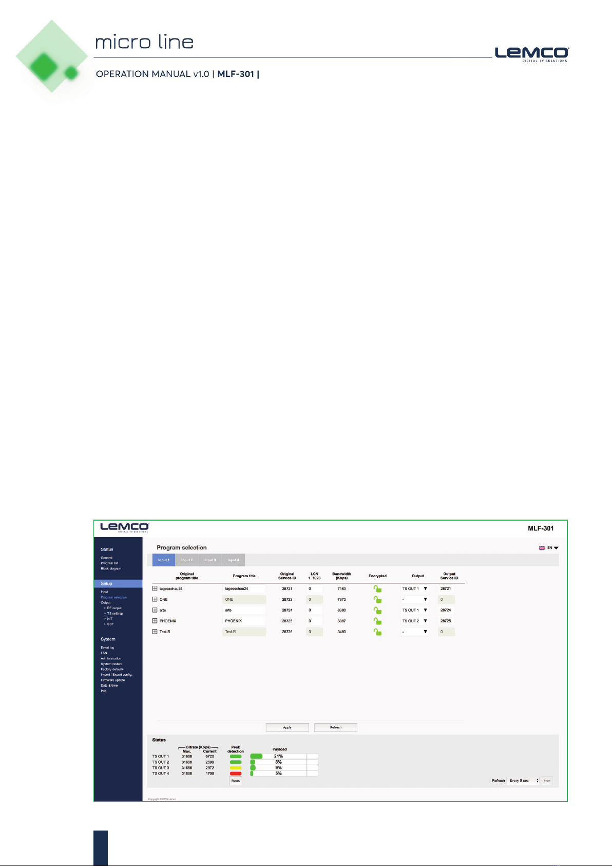
The embedded web server of the MLF-301 provides a very friendly user interface as
well as the ability of remote or local control of the device via Ethernet.
Its small size and its powerful features render the MLF-301 the ideal solution in cases
we want to distribute FTA (Free-To-Air) TV programs coming from satellite (DVB-
S/S2/S2X) sources to a CATV installation using the DVB-T/C or IP technology.
3.2 - Features
zx w 4 x independent multi-standard inputs DVB-S/S2/S2X
zx w Multi-stream support
zx w 4 x RF output DVB-T/C (software selectable)
zx w Gbit IP streaming (up to 64 x SPTS / 4 x MPTS)
zx w “Pool” technology
zx w MER value > 42dB
zx w Dual power supplies offering redundancy mode
zx w PID Filtering
zx w Custom NIT/SDT
zx w Local or remote control via webserver
zx w Very friendly user interface
zx w Wall or rack mount options
zx w SNMP v2
zx w Ultra-compact size
zx w 5year warranty
3.2.1 - Auto-reset functions and watchdog
During the normal operation of the MLF-301, the main CPU monitors all the internal
parts in order to ensure that the device works normally. In case of an internal error or
module failure, the MLF-301 immediately initiates the recovery procedure by resetting
the appropriate module or the device. Finally, watchdog timers ensure that the device
will be reset in case of CPU failure.

5
3.2.2 – Multi-stream SAT reception
The MLF-301 is able to receive and analyze any kind of multi-stream satellite signal.
3.2.3 - “Pool” technology
The MLF-301 supports “pool” technology, meaning that the user is able to select any
TV or Radio program from any input and assign it to any of the 4 outputs providing
great flexibility.
3.2.4 - DVB-T or DVB-C compliant
The user is able to software select the modulation standard, between DVB-T and DVB-
C, of the MLF-301 without the need of any firmware upgrade.
3.2.5 - IP streaming
The MLF-301 is able to make IP streaming of all programs coming from the 4x RF in-
puts using UDP or RTP protocol in multicast/unicast IP addresses. The max. output bi-
trate can be up to 480 Mpbs.
3.2.6 – Custom NIT/SDT
Using the MLF-301 the user is able to create custom NIT and SDT tables according to
his needs.
3.2.7 – Dual power supplies
The MLF-301 is powered from one or two external power supplies of +12VDC/2.5A. In
case we connect two external power supplies then they will work in redundancy mode.
Thus, in case of failure of one of the two external power supplies the device will con-
tinue working without stoping.
3.3 – Block Diagram
S
DVB-
S/
/
S2/S2X
S
DVB-
S/
/
S2/S2X
S
DVB-
S/
/
S2/S2X
30-MLF
(6
4
64 SPTS/4 MP
/
T/
VB-xD
4
1
T
IP
C
/
P
TS)
S
DVB-
S/
/
S2/S2X
(6
64 SPTS/4 MP

6
3.4 - Product drawing views
1 2 3 4
5
6
5
1. RF out
2. IPTV streaming port
3. LAN control port
4. RF inputs
5. Power supply inputs
6. Fan cooler

7
4. INSTALLATION
4.1 - General
The MLF-301 has a very friendly interface for programming and monitoring purposes.
The user is able to gain access to the embedded webserver, by opening an Internet
browser (e.g. Internet Explorer, Firefox or Chrome) and type the following static
IP: 192.168.1.205.
The default username and password are the following:
Username: admin
Password: 12345
4.2 - Embedded Webserver
Status
4.2.1 - “General” page
Every time that the user is connected to the device, the “General” page (Figure No 1) is
loaded providing a current general status information of the device.
Status - Inputs 1…4
In these fields, the user is able to see the status of each tuner e.g. If it is locked / un-
locked or disabled, the working mode eg. DVB-S/S2/S2X etc.
Figure No 1

8
Outputs – Modulator 1…4
In these fields, the user is able to see the status of all the RF outputs of the device such
as modulator’s state, RF output frequencies and modulation settings.
System
This section provides general information of the device, like internal status of all device’s mod-
ules, CPU temperature and fan state as well as error codes for troubleshooting purposes.
4.2.2 - “Program list” page
In “Program list” page (Figure No 2) the MLF-301 provides information of all programs
that are currently being distributed via its four RF and IP outputs.
At the same time, the device offers the whole channel list to be exported under the
follow file types:
zx w Excel – All the program list is exported in .xlsx format
zx w CSV – All the program list is exported in .csv format
zx w M3U – All the program list is exported in .m3u
4.2.3 - “Block diagram” page
The “Block diagram” page (Figure No 3) provides a general view of device’s internal
modules and architecture.
All icons are clickable providing the ability to the user to go directly to the setup page
of all internal modules of the device. The grey icons mean that the current module is
disabled.
Figure No 2

9
Figure No3
Figure No 4
Setup
4.2.4 - “Input” page
In the “Input” page (Figure No 4) the user is able to select the working mode for each
input.
There are four tabs, one for each input. The user is able to select between the DVB-
S/S2/S2X mode and disable as follow:

10
For Satellite signal reception the user must select DVB-S/S2/S2X mode:
1. Tuner Enabled/Disabled - Enable or disable the specific tuner
2. SAT or IF frequency – Select how to insert the SAT frequency
3. Symbol rate – Insert the symbol rate
4. LNB voltage – Select the LNB voltage (13V,18V,OFF)
5. Band – Select the appropriate SAT band (works only if IF frequency is selected as
input method)
6. DiSEqC – Select DiSEqC A, B, C, D
Once all settings are being written for both tuners, the user must click the “Apply” but-
ton to begin the lock process.
Multi-stream section
In case the tuner is lock to a satellite multi-stream transponder the first available
stream will be chosen by default. The user is able to freely select which stream he
wants to receive/ distribute from the Stream ID selection area.
Tuner status
For each input the MLF-301 provides several information such as tuner status
(Locked/Unlocked), total bitrate, signal strength, quality etc.
4.2.5 - “Program Selection” page
In the “Program Selection” page (Figure No 5) the user is able to select any program
from any input and assign it to any output using the “pool” technology.
Figure No 5

11
There are 4 tabs, one for each input. Each tab depicts all the TV and Radio programs
from the input that has being selected during the “Input page” processes.
When the user selects one input, the device’s multiplexer does a real time analysis and
depicts the program list from this specific input. For each program the MLF-301 pro-
vides the following information/options:
zx w Original Program Title – which is the name of the program
zx w Program Title – The ability to enter a custom name for this specific program
zx w Original Service ID – which is the original Service ID number of the program
zx w LCN No – which is the logic channel number of the program
zx w Bandwidth – which is the bitrate of the program in Kbps
zx w Encrypted – which depicts if the program is encrypted or not
zx w Output – To select in which the program must be assinged
zx w Output Service ID – The user is able to provide custom Service ID number
Each program title has a small cross at the left which can be expanded if the user will
click on it. During this procedure, all the available PIDs of this specific program are
reveled (Figure No 6). In this case, the user is able to select/deselect which PID want
to be outputted.
Using the Drop-down menu from “Output” column (Figure No 7) the user is able to as-
sign any program to any of the four outputs. By doing the same process for each pro-
gram, from all inputs the user is able to create his own 4 custom multiplex in the output.
Figure No 6

12
Figure No 7
Figure No 8
Caution!
The number of programs that the MLF-301 is able to distribute de-
pends on the resolution (SD, HD, 4K etc.), the compression (MPEG2,
H.264 etc…) and in general from the total bitrate of each program.
For example, if we select the following DVB-T setting for the four mod-
ulators on MLF-301 outputs:
zx w Constellation: 64 QAM
zx w Guard Interval: 1/32
zx w Code rate: 7/8
zx w Bandwidth: 8 MHz
According to Appendix A we will have a total output bitrate of
31.67Mbps/ modulator. That means that we can select as many pro-
grams as the user wants but their total bitrate must not exceed the
31.67Mbps, otherwise artifacts may occur.

13
The status section in (Figure No 8) provides a general idea to the user of the current
payload (according to the selected programs) comparing it to the max. output payload.
It is recommended that the user must not exceed the 85% from each output, since all
the bitrate are variable according to their specific content.
Peak Detection mechanism
As shown in Figure No 8 there is a colored indicator of the peak detection mechanism,
for each output transport stream. This indicates if any overflow has occurred on mod-
ulator’s output bitrate with the following colors:
zx w Green – No overflow occurred
zx w Yellow – No overflow occurred but the input bitrate is close to the output bitrate
zx w Red – Overflow occurred. The user must decrease the input bitrate
4.2.6 - “RF Output” page
In the “RF Output” page (Figure No 9) the user is able to setup the RF output settings
of the MLF-301.
Figure No 9

14
With the use of the radio buttons the user is able to select the mode that the MLF-301
will operate as follows:
DVB-T: 4 x modulator working in DVB-T standard
DVB-C: 4 x modulator working in DVB-C standard
IP only: All modulators are disabled, the device does IP streaming only
For each modulator in DVB-T mode the user is able to setup the following parameters:
zx w Frequency – The output frequency of the first modulator*
zx w Constellation – The constellation of the first modulator*
zx w Code Rate – The coder rate of the first modulator*
zx w Guard Interval - The guard interval of the first modulator*
zx w Channel Bandwidth – The channel bandwidth of the first modulator*
zx w Modulation – The modulation type of the first modulator*
zx w Enable/Disable – Enable or disable the current modulator
zx w Output level – Adjust the output level for each modulator from 70-90dΒμV.
* All the four outputs of the MLF-301 operate in adjacent RF output channels. This means
that the user setups only the first modulator and all the other three modulators have the
same settings and automatically are being programmed in adjacent channels.
E.g. If the user sets the CH21 in UHF band on modulator No1 the other three modulators
will be automatically set to CH22, CH23 and CH24, respectively.
The status section in (Figure No 10) provides a general idea to the user of the current
payload (according to the selected programs) comparing to the max. output payload.-
It is recommended that the user must not exceed the 85% from each output, since all
the bitrate are variable according to their specific content.
Figure No 10

15
4.2.7 - “IP streaming” page
In “IP streaming” section the user is able to setup the IP streamer of the device..
In Figure No 11 we have general settings of the IP streamer as follows:
zx w IP address: This is the IP address of the streamer for ping purposes.
zx w MAC address: This is the MAC address of the streamer
zx w IGMP: The user is able to select IGMP v2 or v3 or disable the IGMP.
The Status section provides a general view of how many programs and in what format
are currently being streamed from the device is its four outputs.
Figure No 11
Figure No 12

16
For each multiplex output the user can setup the following settings:
TS ID: Which is the ID No of the specific multiplex (1…65535)
Net ID: Which is the Net ID No of the specific multiplex (1…65535)
Original Net ID: Which is the Org. Net ID No of the specific multiplex (1…65535)
Network Name: Which is the network name of the specific multiplex
NIT: Choose from Global, Basic, Default and Custom
LCN provider: Choose the appropriate LCN provider (EACEM, ITC, Nordig, APN)
In order to setup the IP address for each program there are four tabs one for each IP
output of the MLF-301.
By selecting e.g. the TS1 tab (Figure No 12) the user is able to setup the IP streamer for
this specific output, following the steps below:
1st step: Select SPTS or MPTS streaming mode.
SPTS mode: Means that each program has its own IP
MPTS mode: Means that all the programs of the current output (e.g.
TS1) will be streamed in a single IP.
2nd step: For each program (in SPTS mode) or for the whole TS (in MPTS mode)
the user is able to assign a multicast IP address from 224.0.0.0 to
239.255.255.255 or a unicast IP address as well as its destination port
and protocol (UDP or RTP).
By repeating the above procedure for all four outputs of the MLF-301, the user is able
to setup the IP streamer of the device.
4.2.8 - “TS settings” page
In this section (Figure 13), the user is able to setup all the TS settings of the four multi-
plex in MLF-301’s output.--
Figure No 13

17
For more information on how to create a custom NIT table please refer to “Lemco NIT
creation guidelines.pdf” document in Lemco’s website.
4.2.10 - “SDT” page
In this section (Figure 15), the user is able to create custom SDT table for each of the four
outputs of the device. Moreover, this section offers the ability to export / import a SDT table.
4.2.9 - “NIT” page
In this section (Figure 14), the user is able to create custom NIT table for each of the four
outputs of the device. Moreover, this section offers the ability to export / import a NIT table.
Figure No 15
Figure No 14

18
For more information on how to create a custom SDT table please refer to “Lemco
SDT creation guidelines.pdf” document in Lemco’s website.
System
4.2.11 - “Event log” page
In “Event log” page (Figure No 16) the system logs all the events occurs in the device
during its operation. These logs are divided in three different categories based on their
priority as follow:
High Using the red color the system logs the events which are of high priority.
Medium Using the orange color the system logs the events which are of medium
priority.
Low Using the red color the system logs the events which are of low priority.
The user has the ability to select which kind of events to display as well as the device
gives the opportunity to export these logs as follow:
zx w Excel – All the program list is exported in .xlsx format
zx w CSV – All the program list is exported in .csv format
Figure No 16

19
4.2.12 - “LAN” page
In “LAN” page (Figure No 17) the user is able to setup all the parameters of the LAN
control of the device as follows:
4.2.13 - “Administration” page
In “Administration” section (Figure No 18) the user is able to change the default pass-
word of the webserver.
zx w DHCP – Enable or disable DHCP
zx w IP address: Set a static IP address for controlling the device
zx w Subnet mask: Set the specific Subnet mask
zx w Gateway: Set the gateway’s IP address
zx w Primary DNS: Set the IP address of the primary DNS
zx w Secondary DNS: Set the IP address of the secondary DNS
zx w Port: Assign the control port
zx w MAC address: Depicts the MAC address of the LAN control
Figure No 17
Figure No 18

20
4.2.14 - “System restart” page
In “System restart” section (Figure No 19) the user is able to apply a full reset to the de-
vice.
Caution!
In case of factory default procedure, the username and password
will be reset unless we select the check box “Keep username &
password after applying factory defaults”.
Figure No 19
4.2.15 - “Factory default” page
In “Factory default” section (Figure No 20) the user is able to apply a factory default
reset either as DVB-T or DVB-C.
Figure No 20
Other manuals for Micro line MLF-301
1
Table of contents
Other Lemco Media Converter manuals
Popular Media Converter manuals by other brands

Linear Technology
Linear Technology LTC3839EUH Demo Manual

Converters.TV
Converters.TV Digital Line Doubler Operation manual

Lumagen
Lumagen Radiance Series Tech Tip

Teracue
Teracue ENC-300-HDSDI user guide

Auralic
Auralic Aries quick start guide

Baumer
Baumer Hubner Berlin MHAP 100 HDmag Mounting and operating instructions