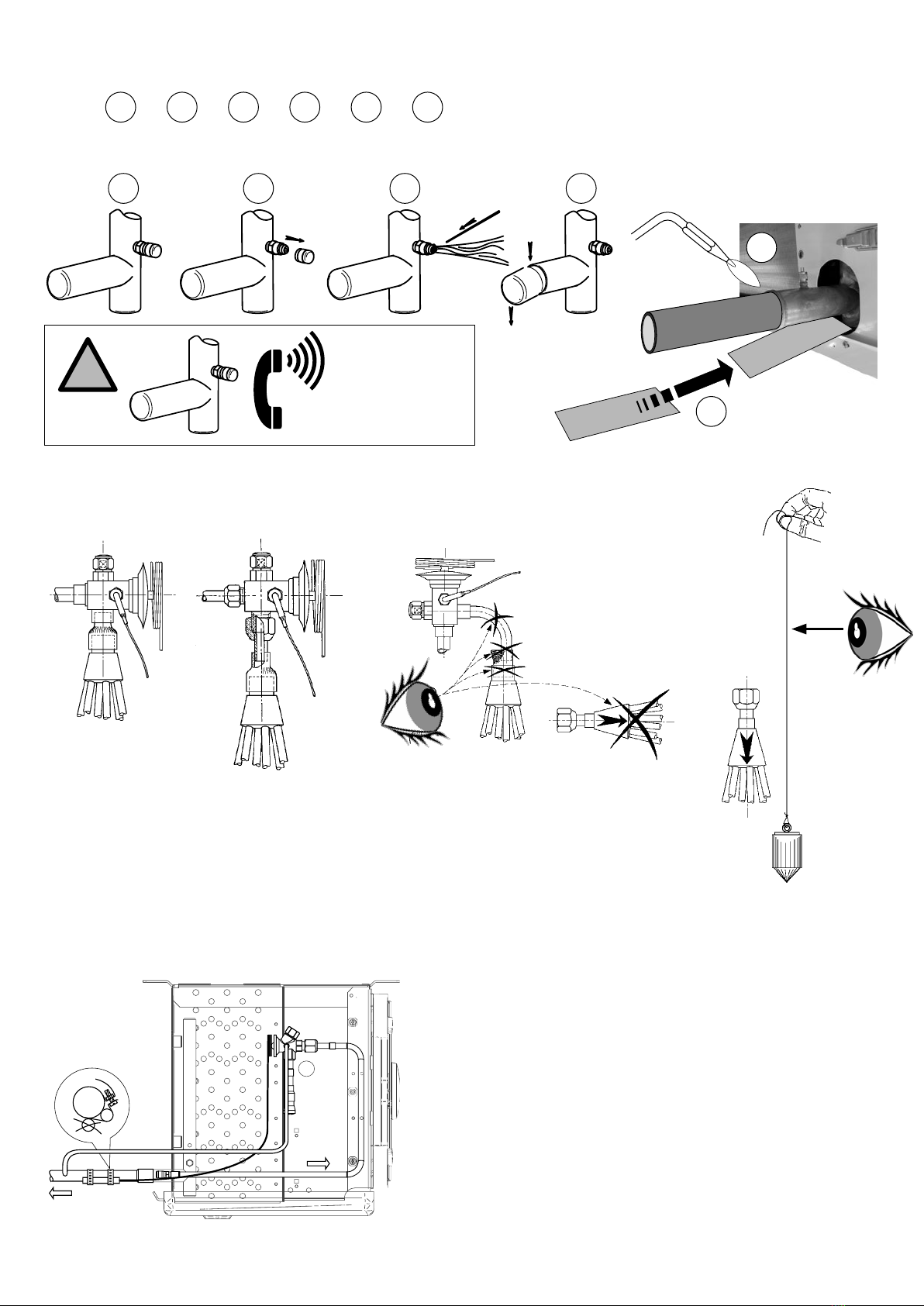
manuals.online logo
Brands
  1. Home
  2. •
  3. Brands
  4. •
  5. Lennox EMEA
  6. •
  7. Accessories
  8. •
  9. Lennox EMEA 3C-A R/E Series User manual

Lennox EMEA 3C-A R/E Series User manual

Notice originale
Original notice
Originale Hinweise
Original aviso
Oryginalna instrukcja
NOTICE TECHNIQUE D’INSTALLATION
INSTALLATION INSTRUCTIONS
INSTALLATIONSNOTIZ
MANUAL TECNICO DE INSTALACION
ORYGINALNA INSTRUKCJA
Unit Coolers
3C-A
N° IN0029100-C
02.2016
3C-A
2
UTILISATION - USE - ANWENDUNG - USAR - ZASTOSOWANIE
La gamme 3C-A est destinée aux applications commerciales et semi-industrielles de réfrigération ou de conservation à basse température
Batteries multi-fluides HFC. L’alimentation des batteries se fait par un distributeur venturi permettant une utilisation en application positive ou négative
avec un même évaporateur. Détendeur électronique compatible.
L’installation en ambiance saline ou vinaigrée et en application fromagerie ou boulangerie n’est pas compatible en configuration standard.
Options carrosserie et batteries spécifiques à prévoir.
Le milieu ambiant de l’évaporateur doit être en conformité avec l’indice de protection IP des ventilations.
L’installation et la maintenance doivent être réalisées par un professionnel et dans le respect des normes.
La notice d’utilisation doit être accessible, lue et comprise par toute personne en contact avec l’évaporateur.
The 3C-A range is designed for commercial and semi industrial refrigeration applications or low temperature storage
Coils multi refrigerant HFC. The coils are supplied via a Venturi distributor for using in positive or negative application with the same unit cooler.
Electronic expansion valve compatible.
Installation in Saline or vinegar atmosphere and cheese or bakery application is not compatible in standard configuration.
Casing options and specific coils are necessary.
The unit cooler environment must be in compliance with IP sign protection motorfans.
The installation and maintenance must be done by a professionnal in compliance with the standards.
The operating instructions must be accessible, read and understood by anyone in contact with the unit cooler
Die 3C-A Baureihe ist für die gewerbliche und semi-industrielle Plus- und Tiefkühlung vorgesehen.
Wärmetauscher zur Anwendung mit unterschiedlichen F-Kältemittel. Die Versorgung des Wärmetausches erfolgt durch einen Venturi-Verteiler, so dass
die Plus- und die Tiefkühlung mit einem selben Verdampfermodell realisiert werden kann.Ein elektronisches Einspritzventil kann eingesetzt werden.
Der Einbau in einem salzhaltigen und essighaltigen Raum und bei Anwendung in Käsereien oder in Bäckereien ist die Standartkonfiguration nicht
geeignet. Optionen wie «spezielle Wärmetauscher und Gehäuse»müssen vorgesehen werden.
Die Umgebung des Verdampfers muss mit der IP Schutzsart der Ventilatoren übereinstimmen.
Der Einbau und die Wartung muss von Fachpersonal nach den dafür gültigen Normen gemacht werden.
Die Installationsnotiz muss zugänglich sein, und dem Fachpersonal für Wartung des Verdampfers zur Verfügung stehen.
La gama 3C-A está diseñada a las aplicaciones comerciales y semi-industrial de refrigeración o conservation
Batería multi-refrigerante HFC. La alimentación de las baterías se lleva a cabo mediante un distribuidor Venturi permitten utilizar un mismo evaporador
para aplicación positiva o negativa. Válvula de expansión electrónica compatible
La instalación en la atmósfera salina o el vinagre y el queso or panadería aplicación no es compatible en la configuración estándar.
Opciones de carrocería y baterías específicas para predecir.
El entorno del evaporador debe estar en conformidad con los desgloses de protección IP
La instalación y el mantenimiento seran realizado por un instalador y de acuerdo con las normas
Las instrucciones de instalación deben ser accesibles, leído y entendido por cualquier persona en contacto con el evaporador
Urządzenia gamy 3C są przeznaczone do komercyjnych i pół-przemysłowych aplikacji chłodniczych lub przechowywania w niskich
temperaturach
Wymienniki przystosowane do pracy z wieloma czynnikami HFC. Wymienniki są zasilane z rozdzielaczy Venturi , co umożliwia zastosowanie tej samej
chłodnicy w aplikacjach mroźniczych i chłodniczych.
Możliwe podłączenie elektronicznego zaworu rozprężnego.
Chłodnicy w standardowej konfiguracji nie należy instalować w korozyjnym środowisku solankowym, w miejscach parowania octu, w magazynach serów
i piekarniach.
Wymagane są specjalne obudowy i wymienniki.
Środowisko w którym pracuje chłodnica musi odpowiadać klasie zabezpieczenia IP silników wentylatorów.
Instalacja i konserwacja muszą być wykonane przez specjalistę zgodnie z obowiązującymi normami.
Instrukcja obsługi musi być dostępna, przeczytana i zrozumiana przez wszystkie osoby mające styczność z chłodnicą.
3C-A
3
SOMMAIRE - SUMMARY - INHALT - RESUMEN - PODSUMOWANIE
1. DEBALLAGE - UNPACKING - AUSPACKEN - DESEMBALAJE - ODPAKOWANIE 3
2. INSTALLATION - INSTALACIÓN - INSTALACJA 4-5
3.1. DIMENSIONS - DIMENSIONNAL - ABMESSUNGEN - DIMENSIONES - WYMIARY
3.2. IMPLANTATION - LOCATION - IMPLANTACIÓN - IMPLANTACJA
3.3. FIXATION AU PLAFOND - FITTING TO CELLING - DECKENBEFESTIGUNG - FIJAIO EN EL TECHO - MOCOWANIE DO SUFITU
3. RACCORDEMENTS FLUIDES - FLUIDS CONNECTIONS 6-7
KÄLTEMITTELANSCHLÜSSE - CONEXIONES FLUIDOS - PRZYŁĄCZA WODY LODOWEJ
3.1. EGOUTTOIR - DRAIN PAN - TROPFWANNE - ESCURRIDOR - TACA OCIEKOWA
3.2. RACCORDEMENT FRIGORIFIQUE - REFRIGERANT PIPING
KÄLTEMITTELANSCHLUSS - CONEXIÓNES FRIGORÍFICAS - UNSTALACJA RUROWA OBIEGU ZIĘBNICZEGO
3.3. MONTAGE DETENDEUR - T.E.V. MOUNTING - MONTAGE DES EXPANSIONSVENTILS
MONTAJE VÁLVULA EXPANSIÓN - MONTAŻ REGULATORA
3.4. MISE EN PLACE BULBE ET EGALISATION DE PRESSION
BULB AND EXTERNAL EQUALIZER LAY-OUT
INSTALLATION DES FÜHLERS UND DES DRUCKAUSGLEICHSSCHLAUCHS
INSTALACION BULBO E IGUALACION DE PRESSION
POŁOŻENIE CZUJKI TERMOSTATYCZNEJ I ZEWNĘTRZNEGO I PRZEWODU WYRÓWNAWCZEGO
4. PASSAGE CABLES - CABLE PASSAGE - KABELDURCHGANG - PASO CABLES - UŁOŻENIE KABLI 8
5. RACCORDEMENTS ÉLECTRIQUE - ELECTRICAL WIRING - ELECTRISCHE ANSCHLÜSSE 9-13
CONEXIONES ELECTRICAS - OKABLOWANIE ELEKTRYCZNE
6. THERMOSTATS – THERMOSTAT – THERMOSTAT – TERMOSTATO - TERMOSTAT 14-15
6.1. INFORMATIONS - INFORMATIONS - INFORMATIONEN - INFORMACIONES - INFORMACJA
6.2.
POSITION THERMOSTATS - THERMOSTAT LOCATION - POSITIONERIERUNG DER THERMOSTATE - LOKALIZACJA TERMOSTATU
7. ENTRETIEN - MAINTENANCE - WARTUNG – MANTENIMIENTO - UTRZYMANIE 16
8. PIECES DETACHEES - SPARE PARTS - ERSATZTEILE - PIEZAS SUELTAS - CZĘŚCI ZAMIENNE 16
1.
DEBALLAGE - UNPACKING - AUSPACKEN
DESEMBALAJE - ODPAKOWANIE
Enlever - Remove - Abnehmen
Retire - Zdjąć
502
118
447
580
635
557
576
6,5
427
610
23
20 461,5
600 mini
461
377
428
7
52,5357
458
67
484
20 421
400 mini
Ø 1’’
96
438
2367
2333
185 2001
210 1500
1000
1867
1833
185 1501
210 1000
1000
1567
1533
185 1201
160 800
1000
1072
138 801
160 400
1038
1000
672
138 401
160
638
1000 772
138 501
210
738
1000 872
138 601
260
838
1000
2367
2333
185 2001
160 1600
1000
1967
1933
185 1601
160 1200
1000
1011
972
185 601,5
299
1000 1611
1572
185 1201,5
299 600
1000
2211
2172
185 1801,5
299 1200
1000 2811
2772
185
399 1600
1201 1201
1000
2811
2772
185
299 1800
1201 1201
1000
484 484 75
+
Ø 1’’
1380,5 1430,5
1380,5 1430,5
40
3C-A 314 .. 3C-A 315 .. 3C-A 316 ..
3C-A 324 ..
3C-A 354 ..
3C-A 344 .. 3C-A 345 ..
3C-A 334 .. 3C-A 335 ..
3C-A 416 .. 3C-A 426 ..
3C-A 436 .. 3C-A 438 ..
3C-A 446 ..
RFA.. R/L .. E/C
Ø 300 MM
Ø 450 MM
2. INSTALLATION – INSTALACIÓN - INSTALACJA
2.1. DIMENSIONS - DIMENSIONNAL - ABMESSUNGEN - DIMENSIONES - WYMIARY
3C-A
5
D
d
D
d d
2.2. IMPLANTATION - LOCATION - IMPLANTACIÓN - IMPLANTACJA
Chambre froide
Refrigerated area
Kälteraum
Cámara frigorífica
Strefa chłodzona
Chambre froide
Refrigerated area
Kälteraum
Cámara frigorífica
Strefa chłodzona
2 (ou plusieurs) évaporateurs
2 (or more) units
2 (oder mehrere) Verdampfer
2 (o más) unidades
2 (lub więcej) urządzenia
2.3. FIXATION AU PLAFOND - FITTING TO CELLING - DECKENBEFESTIGUNG
FIJAIO EN EL TECHO - MOCOWANIE DO SUFITU
!
3C-A3... Ø 8
3C-A4... Ø 10
Ecrous de sécurité - Safety nuts - Sicherungsmuttern
Tuercas de seguridad - Nakrętki zabezpieczające
Les supports de fixation doivent être plaqués au plafond
The mounting brackets must be tightened against the ceiling surface
Die halterung müssen dicht an der decke
Soportes de montage estrictamente para techo
Wsporniki montażowe należy dokręcać na powierzchni sufitu
!
!
D: Ø 300 mm = 400 mm - Ø 450 mm = 600 mm
d: Prévoir les dégagements ou distances nécessaires
d : pour démontage des résistances électriques.
d: Envisage clearances or distances required
d : to disassembly electrical heaters.
d: Genug Seitenabstand muss für den Austausch
d : der elektrischen Heizung vorgesehen werden.
d: Proveer espacios libres y las distancias necesarias
d : para desmantelar las resistencias eléctricas.
d : Należy uwzględnić odstępy lub odległości wymagane
d : do demontażu grzałek elektrycznych.
Idéalement, installation évaporateur(s) le plus loin possible de la porte de la chambre froide.
Pour les chambres négatives, en cas de servitude d’ouverture prolongée de porte prévoir un rideau a lanière.
Ideally, unit cooler(s) as far as possible from the door of the cold room.
For negative rooms, in case of prolonged door opening servitude provide a curtains strips.
Die optimale Installation ist so weit wie möglich von der Eingangstür des Kälteraumes entfernt.s.
Bei Tiefkühlräumen sollte im Fall längerer Öffnungszeiten ein Türvorhang vorgesehen werden.
Idealmente, instalación de los evaporadores lo más lejos posible de la puerta de la cámara frigorífica.
Para las cámaras negativas, en caso de apertura prolongada de la puerta, prever una cortina de tiras
Chłodnicę(e) należy umieścić możliwie jak najdalej od drzwi komory chłodniczej.
W komorach mroźniczych, w przypadku długotrwałego otwarcia drzwi należy zainstalować kurtyny paskowe.
D
d
D
d d
3C-A
6
3C-A ... R / E 4 mm
3C-A .... - R / E 3142 3143 3145 3155 3165 3243 3245 3343 3344 3345 4165 3354 4166
Entrée - Inlet - Eintritt - Entrada - Wejście
Ø (1) 3/8 ODF 5/8 5/8 5/8 5/8 5/8 5/8 5/8 5/8 5/8 7/8 5/8 7/8
Sortie - Outlet - Austritt - Salida - Wyjście
Ø OD (2) 3/8 ODF 5/8 5/8 5/8 5/8 7/8 7/8 7/8 7/8 7/8 7/8 7/8 7/8
3C-A .... - R / E 3444 3445 3455 4263 3545 4264 4265 4266 4364 4366 4386 4466
Entrée - Inlet - Eintritt - Entrada - Wejście
Ø (1) 5/8 7/8 7/8 7/8 7/8 1'' 1/8 1'' 1/8 1'' 1/8 1'' 1/8 1'' 3/8 1'' 3/8 1'' 3/8
Sortie - Outlet - Austritt - Salida - Wyjście
Ø OD (2) 7/8 1'' 1/8 1'' 3/8 1'' 3/8 1'' 3/8 1'' 3/8 1'' 3/8 1'' 3/8 1'' 5/8 2'' 1/8 2'' 1/8 2'' 1/8
3C-A ... L / C 6 mm
3C-A .... - L / C 3143 3144 3145 3155 3165 3243 3244 3245 3343 3344 4165 3345 3354
Entrée - Inlet - Eintritt - Entrada - Wejście
Ø (1) 5/8 5/8 5/8 5/8 5/8 5/8 5/8 5/8 5/8 5/8 5/8 5/8 5/8
Sortie - Outlet - Austritt - Salida - Wyjście
Ø OD (2) 5/8 5/8 5/8 5/8 5/8 7/8 7/8 7/8 7/8 7/8 7/8 7/8 7/8
3C-A .... - L / C 4166 3444 3445 4263 3455 3545 4264 4266 4364 4366 4386 4466
Entrée - Inlet - Eintritt - Entrada - Wejście
Ø (1) 7/8 5/8 7/8 7/8 7/8 7/8 1'' 1/8 1'' 1/8 1'' 1/8 1'' 3/8 1'' 3/8 1'' 3/8
Sortie - Outlet - Austritt - Salida - Wyjście
Ø OD (2) 7/8 7/8 1'' 1/8 1'' 3/8 1'' 3/8 1'' 3/8 1'' 3/8 1'' 3/8 1'' 5/8 2'' 1/8 2'' 1/8 2'' 1/8
(1) Distributeur : mâle à braser
Distributor: Male to be brazed.
Verteilerkopf: Lötanschluss Außendurchmesser.
Distribuidor: macho para soldar
Rozdzielacz: Złącze męskie do twardego lutowania.
(2) OD : Raccordement mâle - ODF : femelle pour recevoir le tube de même diamètre
OD : Male connector - ODF: Female to receive a tube of the same diameter.
OD: Anschluss Außendurchmesser - ODF: Lötanschluss Innendurchmesser.
OD: Conexión macho - ODF: hembra para acoger el tubo del mismo diámetro
OD: Złącze męskie - ODF: Złącze żeńskie pod rurkę o tej samej średnicy.
50 W/m
Retour d'air
Air return
Zurückströmende Raumluft
Siphon
trap
sifon
syfon
Θ: -2 →-21°C
0,3 m/metre
+ isolation
insulation
Isolierung
aislamiento
izolacja
Retorno de aire
Powrót powietrza
50 W/m
Siphon
trap
sifon
syfon
Θ: -2 →-21°C
0,3 m/metre
+ isolation
insulation
Isolierung
aislamiento
izolacja
Plastique
Plastic
Kunststof
Plástico
Plastikowe
Cuivre
Copper
Kupfer
Cobre
Miedź
3.1. EGOUTTOIR - DRAIN PAN - TROPFWANNE - ESCURRIDOR - TACA OCIEKOWA
→1→ 2→ 3→ 4→ 5
2
5
1
3
4
2
3.
RACCORDEMENTS FLUIDES - FLUIDS CONNECTIONS - KÄLTEMITTELANSCHLÜSSE
CONEXIONES FLUIDOS - PRZYŁĄCZA WODY LODOWEJ
3C-A
7
3.2. RACCORDEMENT FRIGORIFIQUE - REFRIGERANT PIPING - KÄLTEMITTELANSCHLUSS
CONEXIÓNES FRIGORÍFICAS - UNSTALACJA RUROWA OBIEGU ZIĘBNICZEGO
→
1
→
2
→
3
→
4
→
5
→
6
6
5
SECURITE - SAFETY - SICHERHEIT - SEGURIDAD - BEZPIECZEŃSTWO
0,2 bar
1 2
0 bar
3 4
+33 (0) 4 72 47 14 44
0 bar
!
3.3. MONTAGE DETENDEUR - T.E.V. MOUNTING - MONTAGE DES EXPANSIONSVENTILS
MONTAJE VÁLVULA EXPANSIÓN - MONTAŻ REGULATORA
3.4. MISE EN PLACE BULBE ET EGALISATION DE PRESSION
BULB AND EXTERNAL EQUALIZER LAY-OUT
INSTALLATION DES FÜHLERS UND DES DRUCKAUSGLEICHSSCHLAUCHS
INSTALACION BULBO E IGUALACION DE PRESSION
POŁOŻENIE CZUJKI TERMOSTATYCZNEJ I ZEWNĘTRZNEGO I PRZEWODU WYRÓWNAWCZEGO
NOTA : Dans les détendeurs actuels, de bonne qualité, «le by-pass» de fluide au travers des passages des
tiges de liaison entre le train thermostatique et le mécanisme, est minime. Par conséquent, la position de
l’égalisation de pression, avant ou après le bulbe est sans importance.
NOTE: With the modern high quality expansion valves, the small refrigerant leakage through the equalizer
line is at a minimum and the valve operation is not affected. Thus, the external equalizer connection could
be made either upstream or downstream of the bulb.
ANMERKUNG: Da bei den heutigen Hochleistungsexpansionsventilen praktisch keine Leckstellen bei den
Kraftübertragungsstiftenmehrvorhandensind,durchdieflüssigesKältemittelüberdieDruckausgleichsleitung
in die Saugleitung gelangen könnte, spielt es keine Rolle, ob die Druckausgleichsleitung vor oder nach dem
Fühler angeschlossen wird.
NOTA : en las válvulas de expansión actuales, de buena calidad, el “bypass” de fluido a través del paso
de las uniones entre el elemento termostático y el mecanismo, es mínimo. Por consecuencia, la posición
del compensador de presión, antes o después del bulbo, no tiene importancia.
UWAGA: Dzięki wysokiej jakości nowoczesnych zaworów rozprężnych, wyciek czynnika przez linię
wyrównawczą jest zmniejszony do minimum, bez negatywnego wpływu na działanie zaworu. Dlatego
przyłącze zewnętrznej linii wyrównawczej wykonuje się w kierunku górnym lub dolnym w stosunku do
czujki termostatycznej.
3C-A
8
3
C
A
-
4
.
.
.
3
C
A
-
4
.
.
.
3CA-3...
4.
PASSAGE CABLES - CABLE PASSAGE - KABELDURCHGANG - PASO CABLES - UŁOŻENIE KABLI
3C-A ... RVU
3C-A 3 ... R/L/E/C
3C-A 4 ... R/L/E/C
3C-A
9
5.
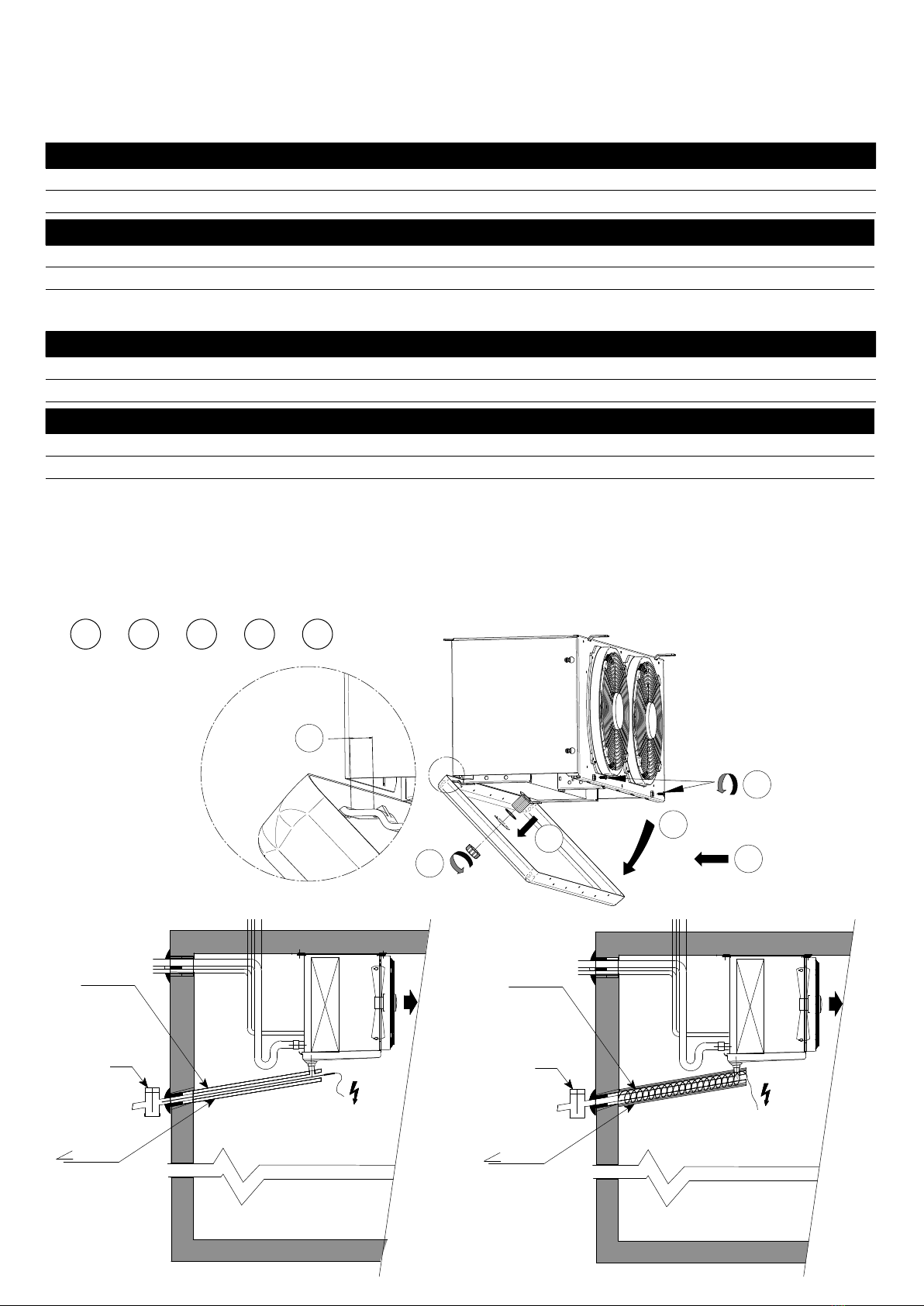
RACCORDEMENT ELECTRIQUE - ELECTRICAL WIRING - ELEKTRISCHE ANSCHLÜSSE
CONEXIONES ELECTRICAS - OKABLOWANIE ELEKTRYCZNE
3C-A ... R / E
3C-A .... - R / E
3142 3143 3145 3155 3165 3243 3245 3343 3344 3345 4165 3354 4166
1500 r.p.m.
IP44 > 3C-A 3…
IP54 > 3C-A 4…
Nb x Ø mm
1x300 1x300 1x300 1x300 1x300 2x300 2x300 3x300 3x300 3x300 1x450 3x300 1x450
230V
1/50-60Hz
W max
72 72 72 72 72 144 144 216 216 216 - 216 -
A max
0,32 0,32 0,32 0,32 0,32 0,64 0,64 0,96 0,96 0,96 - 0,96 -
230-400V
3/50Hz
W max
----------450-450
A max
----------1-1
3C-A .... - R / E
3444 3445 3455 4263 3545 4264 4265 4266 4364 4366 4386 4466
1500 r.p.m.
IP44 > 3C-A 3…
IP54 > 3C-A 4…
Nb x Ø mm
4x300 4x300 4x300 2x450 5x300 2x450 2x450 2x450 3x450 3x450 3x450 4x450
230V
1/50-60Hz
W max
288 288 288 - 360 - - - - - - -
A max
1,28 1,28 1,28 - 1,60 - - - - - - -
230-400V
3/50Hz
W max
- - - 900 - 900 900 900 1350 1350 1350 1800
A max
- - - 2 - 2 2 2 3 3 3 4
3C-A ... L / C
3C-A .... - L / C
3143 3144 3145 3155 3165 3243 3244 3245 3343 3344 4165 3345 4166
1500 r.p.m.
IP44 > 3C-A 3…
IP54 > 3C-A 4…
Nb x Ø mm
1x300 1x300 1x300 1x300 1x300 2x300 2x300 2x300 3x300 3x300 1x450 3x300 1x450
230V
1/50-60Hz
W max
72 72 72 72 72 144 144 144 216 216 - 216 -
A max
0,32 0,32 0,32 0,32 0,32 0,64 0,64 0,64 0,96 0,96 - 0,96 -
230-400V
3/50Hz
W max
----------450-450
A max
----------1-1
3C-A .... - L / C
3354 3444 3445 4263 3455 3545 4264 4266 4364 4366 4386 4466
1500 r.p.m.
IP44 > 3C-A 3…
IP54 > 3C-A 4…
Nb x Ø mm
3x300 4x300 4x300 2x450 4x300 5x300 2x450 2x450 3x450 3x450 3x450 4x450
230V
1/50-60Hz
W max
216 288 288 - 288 360 - - - - - -
A max
0,96 1,28 1,28 - 1,28 1,6 - - - - - -
230-400V
3/50Hz
W max
- - - 900 - - 900 900 1350 1350 1350 1800
A max
- - - 2 - - 2 2 3 3 3 4
3C-A ...
3C-A ....
3142 3143
3145
3155 3165 3243
3245
3343
3344
3345
3354 3444
3445
3455 3545 4165
4166
4263
4264
4265
4266 4364
4366
4386 4466
E1U
W 580 870 1080 1290 1740 2580 3240 3450 4320 4320 1080 2160 2160 3240 3960 3960
230V/1
A 2,5 3,8 4,7 5,6 7,6 11,2 14,1 - - - 4,7 9,4 9,4 14,1 - -
400V/3
A - - - - - - - 4,98 6,24 6,24 - - - - 5,72 5,72
E2U
W 870 870 1080 1290 1740 2580 3240 3450 4320 4320 2160 4320 4320 6480 7920 7920
230V/1
A 3,8 3,8 4,7 5,6 7,6 11,2 14,1 - - - 9,4 - - - - -
400V/3
A - - - - - - - 4,98 6,24 6,24 - 6,24 6,24 9,35 11,43 11,43
E/C
W 870 1740 2160 2580 3480 5160 6480 6900 8640 8640 3240 6480 6480 9720 11880 11880
230V/1
A 3,8 7,6 9,4 11,2 15,1 - - - - - - - - - - -
400V/3
A - - - - - 7,4 9,4 10 12,5 12,5 4,7 9,4 9,4 14 17,1 17,1
HG1 W 290 290 360 430 580 860 1080 1150 1440 1440 360 720 720 1080 1320 1320
230V/1
A 1,26 1,26 1,57 1,87 2,52 3,74 4,70 5,00 6,26 6,26 1,57 3,13 3,13 4,70 5,74 5,74
RVU W 25 25 25 25 50 75 75 100 100 125 35 70 70 105 105 140
230V/1
A 0,12 0,12 0,12 0,12 0,24 0,36 0,36 0,48 0,48 0,6 0,16 0,32 0,32 0,48 0,48 0,64
Option
Opcion
Opcja
1500
r.p.m.
IP54
M60 W - - - - - - - - - - 660 720 720 1980 1980 2640
400V/3/60hz
A max - - - - - - - - - - 1,15 2,3 2,3 3,45 3,45 4,6
MM5 W - - - - - - - - - - 530 1060 1060 1590 1590 2120
230V/1/50hz
A max - - - - - - - - - - 2,6 5,2 5,2 7,8 7,8 10,4
2V5 W - - - - - - - - - - 540 1080 1080 1620 1620 2160
400V/3/50hz
A max - - - - - - - - - - 1 2 2 3 3 4
MP5 W - - - - - - - - - - 500 1000 1000 1500 1500 2000
230V/1/50hz
A max - - - - - - - - - - 2,2 4,4 4,4 6,6 6,6 8,8
EC W 85 85 85 85 170 255 255 340 340 425 - - - - - -
230V/1/50-60hz
A max 0,8 0,8 0,8 0,8 1,6 2,4 2,4 3,2 3,2 4,0 - - - - - -
3C-A
10
M
1
L1
N
B
N
M
N
N
2µF
M
1
M
1
M
1
L1
N
B
N
M
N N
2µF
M
1
M
1
M
1
M
1M
1
M
1M
1
L1
N
B
N
M
N
N
2µF
L1
BL
J
N
R
M
5708L
5709L
FD DC
2TH OPTION
Y
X
Z
UW
V
PE
T
batterie - coil
verdampferblocks
R
R
RR
400 V/3
230 V/3 230 V/1
21
COUPLAGE USINE
FACTORY COUPLING
WERKSEITIGE KOPPLUNG
ACOPLAMIENTO FABRICA
PRZYŁĄCZA FABRYCZNE
B: Bleu - Blue - Blau - Azul - Niebieski
N: Noir - Black - Schwarz - Negro - Czarny
M : Marron - Brown - Braun - Marron - Brązowy
3C-A 31.. 3C-A 32.. / 33..
3C-A 34.. / 35..
3C-A 3... E/C
3C-A 3... R/L - E1U / E2U 3C-A 3... - 2TH
3C-A 4... - 2TH
ATTENTION / CAUTION / ACHTUNG / ATENCION / UWAGA
Couper l’alimentation avant toute intervention
Isolate the power supply before working on the appliance
Vor jedem Eingriff Strom abschalten
Corten la alimentación eléctrica antes de trabajar
Wyłącz zasilanie przed rozpoczęciem pracy
Protecteurs thermiques non raccordés = garantie annulée
Overload protectors not connected = cancelled guarantee
Motorschutzschalter nicht angeschlossen
= von der Garantie ausgeschlossen
Protector termico no conectado = garantia cancelada
Nie podłączenie zabezpieczeń przeciążeniowych
= unieważnienie gwarancji
3C-A
11
M
1
M
1
M
1
M
1M
1
M
1M
1
B
N
M
V/J
L
N
SL
r.p.m.1
r.p.m.2
M
1
M
1
M
1
M
1M
1
M
1M
1
B
N
M
V/J
L
N
SL
1
23
4
3
1
24
U
V
W
101
102
101
102
U
V
W
U
V
W
101
102
101
102
U
V
W
L1
L2
L3
L1
L2
L3
L1
L2
L3
L1
L2
L3
V/J
B
M
G
M
N
N
V/J
G
G
V
J
M
B
BL
TW
W2 U2 V2 TW
U1 V1 W1
400V/3/50-60Hz
V W
U
ZXY
Ω
Ω
Ω
UX
VY
WZ
230-400V/3/50Hz
230 V/1
230 V/3 400 V/3
1
2
COUPLAGE USINE
FACTORY CONNECTED
WERKEITIGE KOPPLUNG
ACOPLAMIENTO FABRICA
PRZYLACZA FABRYCZNE
3C-A 4... E/C
3C-A 4... R/L - E1U / E2U
3C-A 4...
3C-A 3... EC3
ATTENTION / CAUTION / ACHTUNG / ATENCION / UWAGA
Couper l’alimentation avant toute intervention
Isolate the power supply before working on the appliance
Vor jedem Eingriff Strom abschalten
Corten la alimentación eléctrica antes de trabajar
Wyłącz zasilanie przed rozpoczęciem pracy
Protecteurs thermiques non raccordés = garantie annulée
Overload protectors not connected = cancelled guarantee
Motorschutzschalter nicht angeschlossen
= von der Garantie ausgeschlossen
Protector termico no conectado = garantia cancelada
Nie podłączenie zabezpieczeń przeciążeniowych
= unieważnienie gwarancji
3C-A
12
123 4
B
R
B
N
M
G
BL
M
V/J
U1
V2
W1
U2V1W2
U1
1
23
4
 
 
 
 
∆
Y
3
1
2 4
V2
W1
U2V1W2 1U1U W2 V1 U2 W1 V2
V2
W1
U2V1W2 1U1U W2 V1 U2 W1 V2
400V/3/50Hz
1
23
4
3
1
24
230V/1/50Hz
N
L
N
L
N
L
N
L
M
B
V/J
PE
Z
U1
U2
V1 W1 W2 U2 V2 TW TW
3
1
24
230V/1/50Hz
N
L
N
L
N
L
N
L
V/J
M
L
N
0-10v/+10v
V/J
M
BB
R
J
NC
GND
RSA
COM
PE
RSB
Bl 1
Bl 2
M
Bl
B
43 2 1
3C-A 4... MM5
3C-A 4... 2V5
3C-A 4... MP5
ATTENTION / CAUTION / ACHTUNG / ATENCION / UWAGA
Couper l’alimentation avant toute intervention
Isolate the power supply before working on the appliance
Vor jedem Eingriff Strom abschalten
Corten la alimentación eléctrica antes de trabajar
Wyłącz zasilanie przed rozpoczęciem pracy
Protecteurs thermiques non raccordés = garantie annulée
Overload protectors not connected = cancelled guarantee
Motorschutzschalter nicht angeschlossen
= von der Garantie ausgeschlossen
Protector termico no conectado = garantia cancelada
Nie podłączenie zabezpieczeń przeciążeniowych
= unieważnienie gwarancji
3C-A
13
3C-A 4... RVU
M1
R1
M2
M3
M4M5
R2R3R4R1

R2
230V/1
L
N
ATTENTION / CAUTION / ACHTUNG / ATENCION / UWAGA
Couper l’alimentation avant toute intervention
Isolate the power supply before working on the appliance
Vor jedem Eingriff Strom abschalten
Corten la alimentación eléctrica antes de trabajar
Wyłącz zasilanie przed rozpoczęciem pracy
Protecteurs thermiques non raccordés = garantie annulée
Overload protectors not connected = cancelled guarantee
Motorschutzschalter nicht angeschlossen
= von der Garantie ausgeschlossen
Protector termico no conectado = garantia cancelada
Nie podłączenie zabezpieczeń przeciążeniowych
= unieważnienie gwarancji
3C-A
14
TH
R. rouge - red - rot - rosso - colorado
M. marron - brown - braun - marrone
N. noir - black - schwarz - nero - negro
J. jaune - yellow - gelb - amarillo
BL. blanc - white - weiss - bianco
THS
?
?
??
J.
J.
Cycle de dégivrage - Defrost cycle
Marche froid
Cooling Pump down Dégivrage
Defrost
Egouttage
Draining
Fixation
Freezing
Marche froid
Cooling
Compresseur
Compressor
1
marche / on
1
marche / on
0
arrêt / off
0
arrêt / off
1
marche / on
1
marche / on
Electrovanne
Solenoid valve
1
marche / on
0
arrêt / off
0
arrêt / off
0
arrêt / off
1
marche / on
1
marche / on
Ventilateur (évaporateur)
Motor fan (unit cooler)
1
marche / on
1
marche / on
0
arrêt / off
0
arrêt / off
0
arrêt / off
1
marche / on
Résistance (évaporateur)
Heater (unit cooler)
0
arrêt / off
0
arrêt / off
1
marche / on
0
arrêt / off
0
arrêt / off
0
arrêt / off
Résistance d’écoulement
Heater draining
0
arrêt / off
0
arrêt / off
1
marche / on
0
arrêt / off
0
arrêt / off
0
arrêt / off
TH (5709L)
TH
R. rouge - red - rot - rosso - colorado
M. marron - brown - braun - marrone
N. noir - black - schwarz - nero - negro
J. jaune - yellow - gelb - amarillo
BL. blanc - white - weiss - bianco
THS
??
??
J.
J.
1
marche / on
1
marche / on
1
marche / on
0
arrêt / off
0
arrêt / off
1
marche / on
0
arrêt / off
0
arrêt / off
0
arrêt / off
1
marche / on
1
marche / on
0
arrêt / off
THS (5708L)
TH
R. rouge - red - rot - rosso - colorado
M. marron - brown - braun - marrone
N. noir - black - schwarz - nero - negro
J. jaune - yellow - gelb - amarillo
BL. blanc - white - weiss - bianco
THS
??
??
J.
J.
1
marche / on
1
marche / on
1
marche / on
1
marche / on
1
marche / on
1
marche / on
6.
THERMOSTATS – THERMOSTAT – THERMOSTAT – TERMOSTATO - TERMOSTAT
6.1. INFORMATIONS – INFORMATIONS – INFORMATIONEN – INFORMACIONES – INFORMACJA
Kit 2TH = TH (5709L) + THS (5708L)
TH :
Thermostat de dégivrage (ou sonde de temp.)
Defrost control thermostat (or heat sensor)
Abtau-Thermostat (oder temperaturfühlers)
Termostato de desescarche (o sondea)
Termostat odtajania (lub czujnik temperatury)
THS :
Thermostat de sécurité
Safety thermostat
Sicherheitsthermostat
Termostato de seguridad
Termostat zabezpieczający
3C-A
15
ou
or
oder
o
3C.. 3...
TH 5708L
TH 5709L
3C.. 4...
20 mm
40 mm
20 mm
40 mm
6.2. POSITION THERMOSTATS - THERMOSTAT LOCATION - POSITIONERIERUNG DER THERMOSTATE
POSICIONAMENTO THERMOSTATOS - LOKALIZACJA TERMOSTATU
3C.. 3..2 3C.. 3..3
3C.. 3..4 3C.. 3..5
3C.. 4...
3C.. 3 ...
TH 5708L
TH 5709L
TH 5708L
TH 5709L
TH 5708L
TH 5709L
TH 5708L
TH 5709L
B
A
C
A
B
C
??
TH - THS
2
2
1
→ 1
→ 2 → A → B → C
3C.. 3..2 3C.. 3..3
3C.. 3..4
3C.. 3..5
3C.. 4...
3C.. 3 ...
TH 5708L
TH 5709L
TH 5708L
TH 5709L
TH 5708L
TH 5709L
TH 5708L
TH 5709L
ou
or
oder
o
3C.. 3...
TH 5708L
TH 5709L
3C.. 4...
20 mm
40 mm
20 mm
40 mm
3C.. 3..2 3C.. 3..3
3C.. 3..4
3C.. 3..5
3C.. 4...
3C.. 3 ...
TH 5708L
TH 5709L
TH 5708L
TH 5709L
TH 5708L
TH 5709L
TH 5708L
TH 5709L
7.
ENTRETIEN - MAINTENANCE - WARTUNG - MANTENIMIENTO - UTRZYMANIE
Nettoyer périodiquement à l’aide d’un produit non agressif et rincer à l’eau claire :
- la batterie : protéger les moteurs a l’aide d’un film plastique, pression maximale 3 bars et jet orienté face à la tranche des ailettes.
- les hélices, les grilles et la carrosserie.
Vérifier à la mise en route et périodiquement, le serrage des vis d’assemblage, l’état et le serrage des composants électriques.
DEFAUT DE FONCTIONNEMENT
Le moteur ne tourne pas : avant toute intervention, vérifier l’alimentation électrique. S’assurer que l’hélice tourne librement.
L’appareil vibre : vérifier les hélices et remplacer le moto-ventilateur défectueux, s’assurer de l’absence de glace sur les hélices.
Couple de serrage fixation motoventilateur : 3.5 N/m +/-0.4 (2.5+1N/m pour ecrou frein)
Clean periodically with a non agressive solution and rinse with clean water:
- coil: protect the motors with a plactic film,maximum 3 bars water pressure and jet facing the fin edges.
- fan blades, fan guards and casing.
At start up and periodically, check for eventual losen screws, the condition and tightening of the electrical connections.
FAILURES
Motor does not turn: before any intervention, check the electric supply. Make sure that the fan blade is turning freely.
The unit vibrates: check the fan blades and replace the fan assembly defective, make sure that fan blades are free of ice.
Torque fixing fan motor : 3.5 N/m +/-0.4 (2.5+1N/m for nut brake).
Folgende Teile regelmäßig mit einem milden Reinigungsmittel reinigen und mit klarem Wasser spülen:
- Batterie: Motoren mit einer Plastikfolie schützen, maximaler Druck des Wasserstrahls, der senkrecht zur Kante der Lamellen gerichtet
sein muß: 3 Bar.
- Ventilatorflügel, Schutzgitter und Gehäuse.
Bei der Inbetriebnahme regelmäßig prüfen, ob alle Schrauben gut festgezogen sind. Zustand und Befestigung der elektrischen
Komponenten überprüfen.
STÖRUNGEN
Der Motor läuft nicht: vor jeglichem Eingriff Stromversorgung überprüfen. Prüfen, ob sich die Ventilatorflügel leichtgängig drehen.
Das Gerät vibriert: Ventilatorflügel überprüfen und defekten ventilatormotor auswechseln. Sicherstellen, daß die Flügeln nicht vereist sind.
Anzugmoment für Befestigungsschrauben der Lüftermotoren: 3.5 N/m+/-0.4 (2.5+1N/m je Schraube)
Limpie periódicamente con un producto no agresivo y aclare con agua limpia:
- la batería: proteja los motores con a film plástico, presión máxima 3 bares y chorro orientado paralelamente a las aletas.
- las hélices, las rejillas y la carrocería.
Verifique la puesta en marcha y periódicamente, el priete de los tornillos de ensambladura, el estado y la sujeción de los componentes
eléctricos.
FALLO DE FUNCIONAMIENTO
El motor no gira: antes de cualquier intervención, verifique la alimentación eléctrica. Cerciórese de que el ventilador gira libremente.
El aparato vibra: comprobar las hélices y sustituir el motoventilador defectuoso, cerciorarse de que no hava hielo en las hélices.
Par de apriete de la fijación del ventilador : 3,5 N/m +/-0,4 (2,5+1 N/m para tuerca freno)
Czyścić okresowo łagodnym detergentem i spłukać czystą wodą:
- wymiennik: osłonić silniki folią z tworzywa sztucznego, maksymalne ciśnienie wody 3 bary, strumień skierować na krawędzie łopatek/
- łopatki, osłony i obudowa wentylatora.
Przy rozruchu i okresowo sprawdzać, czy śruby są mocno dokręcone, stan i zamocowanie połączeń elektrycznych.
AWARIE
Silnik nie obraca się: przed przystąpieniem do naprawy należy sprawdzić zasilanie elektryczne.
Upewnić się, że koło wentylatora obraca się swobodnie.
Urządzenie wibruje: sprawdzić łopatki wentylatora i wymienić tę uszkodzoną, upewnić się, że łopatki wentylatora nie są oblodzone.
Moment obrotowy dokręcania śrub mocujących silnik wentylatora: 3.5 N/m +/-0.4 (2.5+1N/m dla przeciwnakrętki).
8.
PIECES DETACHEES - SPARE PARTS – ERSATZTEILE - PIEZAS SUELTAS - CZĘŚCI ZAMIENNE
Demandez notre catalogue «pièces détachées»
Ask for our liste of spare parts
Forden Sie unseren Ersatzteilkatalog an
Pida nuestro catálogo “piezas de repuesto”
Zapytaj o naszej Lista części zamiennych
42 rue Roger Salengro - BP 205
69741 GENAS CEDEX - FRANCE
Tél. : +33 4 72 47 14 44
Fax : +33 4 72 47 13 99
[email protected]
42 rue Roger Salengro - BP 205 69741
GENAS CEDEX - FRANCE
Tel. : +33 4 72 47 13 00 - Fax : +33 4 72 47 13 96
www.lennoxemea.com
LENNOX EMEA se réserve le droit d'apporter toute modification sans préavis.
LENNOX EMEA reserves itself the right to make changes at any time without preliminary notice.
LENNOX EMEA Angaben und Abbildungen unverbindlich. Änderungen vorbehalten.
LENNOX EMEA se reserva el derecho de aportar cualquier modificación sin preaviso.

This manual suits for next models

27

Other Lennox EMEA Accessories manuals

Lennox EMEA FRIGA-BOHN HK REFRIGERATION 3C-E Series User manual

Lennox EMEA

Lennox EMEA FRIGA-BOHN HK REFRIGERATION 3C-E Series User manual

Lennox EMEA FRIGA-BOHN NK Series User manual

Lennox EMEA

Lennox EMEA FRIGA-BOHN NK Series User manual

Lennox EMEA 3C-A Series User manual

Lennox EMEA

Lennox EMEA 3C-A Series User manual

Lennox EMEA 3C Series User manual

Lennox EMEA

Lennox EMEA 3C Series User manual

Lennox EMEA Euromon 100 Series Operating instructions

Lennox EMEA

Lennox EMEA Euromon 100 Series Operating instructions

Popular Accessories manuals by other brands

Cognex In-Sight 1010 Getting started

Cognex

Cognex In-Sight 1010 Getting started

ipf electronic RO570900 manual

ipf electronic

ipf electronic RO570900 manual

FAAC XP15W manual

FAAC

FAAC XP15W manual

Balluff BML-S1G0 7 M5E 0 Series Condensed guide

Balluff

Balluff BML-S1G0 7 M5E 0 Series Condensed guide

Life Giving Warmth The Cozee user manual

Life Giving Warmth

Life Giving Warmth The Cozee user manual

Datalogic VS-CRX Product reference guide

Datalogic

Datalogic VS-CRX Product reference guide

Aeotec MultiSensor installation instructions

Aeotec

Aeotec MultiSensor installation instructions

Balluff BOS R254K-UUI-LH10-S4 user guide

Balluff

Balluff BOS R254K-UUI-LH10-S4 user guide

Rice Lake Ranger Series Operation manual

Rice Lake

Rice Lake Ranger Series Operation manual

Russound DTI-1 instruction manual

Russound

Russound DTI-1 instruction manual

ELRO DB260 manual

ELRO

ELRO DB260 manual

Intermatic IOS-CMP-U Installation and configuration instructions

Intermatic

Intermatic IOS-CMP-U Installation and configuration instructions

ekwb EK-FC970 GTX WF3 Backplate Installation and mounting manuals

ekwb

ekwb EK-FC970 GTX WF3 Backplate Installation and mounting manuals

Isotronic COMBI-Duplex Instructions for use

Isotronic

Isotronic COMBI-Duplex Instructions for use

Encelium VISION Sensor installation instructions

Encelium

Encelium VISION Sensor installation instructions

Stobag Airomatic PS 4000 quick start guide

Stobag

Stobag Airomatic PS 4000 quick start guide

SICK DT1000 operating instructions

SICK

SICK DT1000 operating instructions

HAUL MASTER 34313 Assembly and operating instructions

HAUL MASTER

HAUL MASTER 34313 Assembly and operating instructions

manuals.online logo
manuals.online logoBrands
  • About & Mission
  • Contact us
  • Privacy Policy
  • Terms and Conditions

Copyright 2025 Manuals.Online. All Rights Reserved.