Lennox EMEA Euromon 100 Series Operating instructions

INSTALLATION,
USER AND MAINTENANCE MANUAL
Refrigeration monoblock
EUROMON
01.2020

1

INDEX
1. PRODUCT SPECIFICATIONS ..................................................................................................................................3
1.1. DESCRIPTION......................................................................................................................................................3
1.2. DESIGNATION......................................................................................................................................................4
1.3. OPERATING LIMITS.............................................................................................................................................4
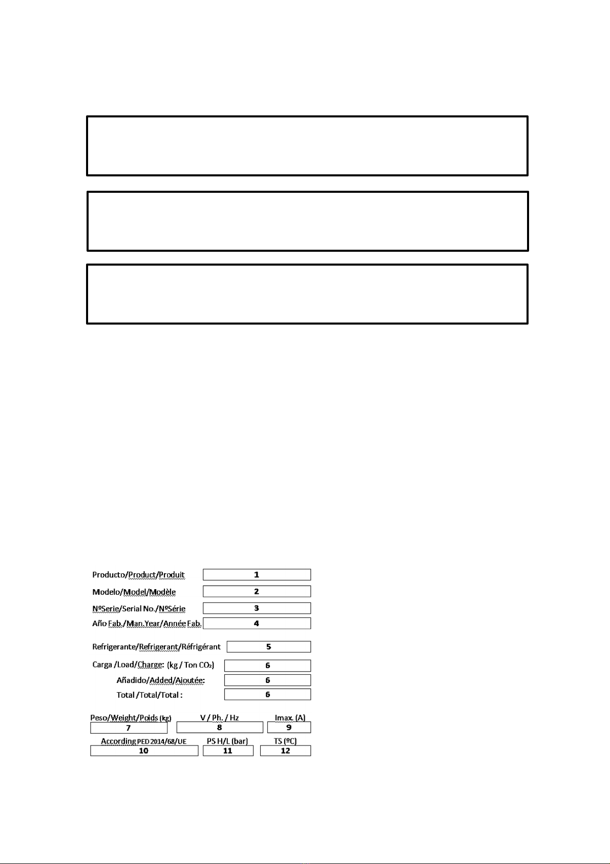
1.4. TECHNICAL CHARACTERISTICS AND DIMENSIONS .......................................................................................4
1.5. EQUIPMENT DESIGN ..........................................................................................................................................5
2. UNIT PREPARATION FOR USE...............................................................................................................................5
2.1. TRANSPORT........................................................................................................................................................5
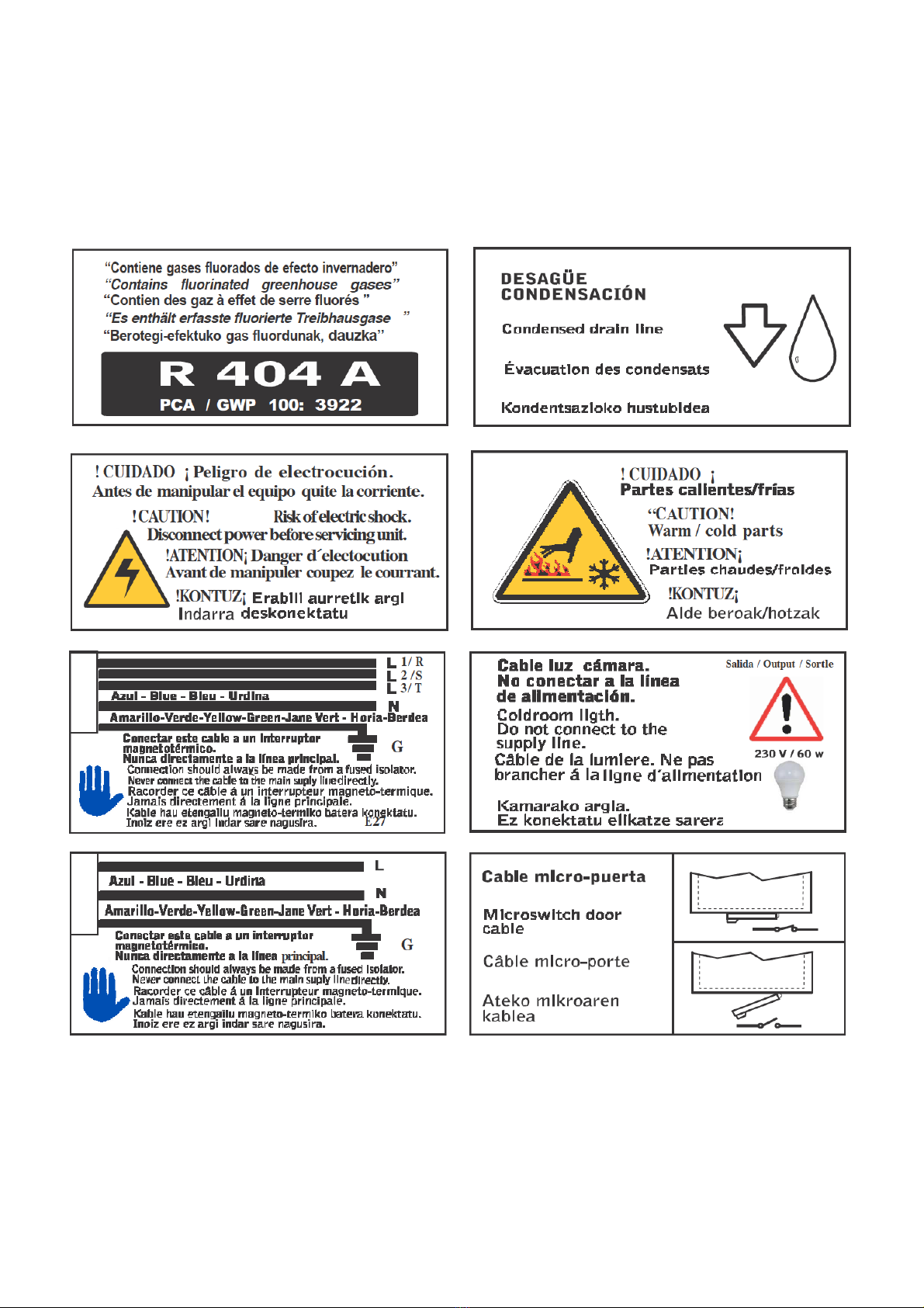
2.2. IMPORTANT SAFETY WARNINGS......................................................................................................................6
2.3. INDICATIONS.......................................................................................................................................................7
2.4. INSTALLING THE UNIT........................................................................................................................................9
2.5. COMPULSORY SPACE TO BE LEFT AROUND THE UNIT ................................................................................9
2.6. ASSEMBLY...........................................................................................................................................................9
2.7. PROTECTIVE DEVICES AND SAFETY MEASURES ........................................................................................11
2.8. DISPOSING OF PACKAGING ............................................................................................................................11
2.9. CONTROLS, ADJUSTMENTS AND CHECKS TO BE MADE.............................................................................11
3. OPERATING INSTRUCTIONS................................................................................................................................11
3.1. CONNECTING THE UNIT TO EXTERNAL POWER SOURCES........................................................................11
3.2. ELECTRICAL POWER CONNECTION...............................................................................................................11
3.3. ADJUSTMENT AND CONTROL .........................................................................................................................12
3.4. COLD ROOM LIGHT...........................................................................................................................................13
3.5. CONTROL DEVICE ............................................................................................................................................13
3.6. CONTROL FUNCTIONS.....................................................................................................................................14
3.7. INDICATOR LIGHTS...........................................................................................................................................15
3.8. ALARM SIGNALS ...............................................................................................................................................15
3.9. RESETTING THE ALARMS ................................................................................................................................15
3.10. PAL/CA ALARM ..................................................................................................................................................16
3.11. P1, P2, P3, P4 ALARM .......................................................................................................................................18
3.12. dA ALARM...........................................................................................................................................................19
3.13. COMPRESSOR ALARM DOES NOT START.....................................................................................................19
3.14. PARAMETER LIST .............................................................................................................................................20
3.15. EXTERNAL COMMUNICATION .........................................................................................................................20
3.16. STARTING UP THE UNIT...................................................................................................................................21
3.17. DIAGRAM OF THE UNIT ELECTRICAL SYSTEM .............................................................................................21
4. MAINTENANCE AND CLEANING...........................................................................................................................21
4.1. MAINTENANCE AND REPAIR OF THE UNIT ....................................................................................................21
4.2. ORDINARY MAINTENANCE ..............................................................................................................................21
4.3. PERIODIC AND PREVENTIVE MAINTENANCE................................................................................................22
4.4. SERVICING TO BE CARRIED OUT BY QUALIFIED STAFF .............................................................................22
4.5. TECHNICAL PROBLEMS ...................................................................................................................................22
4.6. FAILURE ANALYSIS...........................................................................................................................................24
4.7. HOW TO ORDER SPARE PARTS......................................................................................................................25
4.8. SCRAPPING THE UNIT......................................................................................................................................25
3
3
4
4
4
5
5
5
6
7
9
9
9
11
11
11
11
11
11
12
13
13
14
15
15
15
16
18
19
19
20
20
21
21
21
21
21
22
22
22
24
25
25
2

1. PRODUCT SPECIFICATIONS
1.1. DESCRIPTION
EUROMON commercial equipments are compact wall compression cooling units, air-cooled, for
cold storage rooms which have a small volume and for use in medium and low temperature,
governed by an intelligent control.The power supply is single phase or three phase depending on
the equipment.They consist of:
1condenser unit installed externally to the cold
room an insulating
2panel for fitting to the wall of the cold room
3an evaporator installed inside the cold room
4an electrical control and command panel, located
in the condenser unit
The EUROMON is a totally compact cooling unit, easy to install and with easy access to the
inside of the unit, making maintenance simple, quick and safe.
-It is constructed in treated sheet metal with a prepainted finish
-Its batteries are built with copper tube and aluminium fins
-The evaporator is forced draught type, with air condensation
-The compressors are hermetic type and they can be supplied to operate with different
refrigerants (R-404A, R-452A, R-449A, R-448A)
The EUROMON are equipped with:
-Refrigerant charge.
-Hermetic compressor.
-Thermostatic expansion valve
-High and low pressure switches.
-Automatic defrosting by hot gas.
-System for partial evaporation of defrosts water.
-Cables for supply, door micro switch and cold room light (2,5 m. each)
-Watertight cold room light.
-Voltage protector
-Condensation control by pressure switch.
-Integrated multifunctional electronic control
-Ceramic Filter Drier
-Probe alert "dirty condenser"
-Insulation panel included.
-Install under roof
This manual is an integral part of the equipment and should ALWAYS accompany it.It must be
protected, at all times, from any possible deterioration during the whole life of the equipment.It
contains the necessary instructions for maintenance technicians and should ALWAYS be easily
accessible to them.
The manufacturer reserves the right to make modifications and /or improve this document
without prior notice.
WARNING
Contains fluorinated greenhouse gases.
3

1.2. DESIGNATION
1.3. OPERATING LIMITS
The EUROMON units are designed for correct continuous functioning between the
temperature limits shown in the following table.
* The cold room needs to be designed as if it was a freezing chamber.
Sound pressure level dB (A) <70 db (A) at 10 m of the unit measured in open field
1.4. TECHNICAL CHARACTERISTICS AND DIMENSIONS
Unit with axial fan (EMB) Unit with centrifugal fan (EMC)
Max. Min.
Refrigeration +10ºC -5ºC *
Freezing -15ºC -25ºC
EMB 2 009 M 1 Z
EMB Indicates the unit family
2Indicates a group within the family
009Indicates the compressor
MIndicates the work range:
M = refrigeration (medium temperature)
L =freezing
1Indicates the voltage
1= 230/1/50
2= 220/1/60
3 =230/3/50
4 =220/3/60
5 = 400/3/50
6 = 380/3/60
7 = 460/3/60
ZZ = R-404A X = R-449A T = R-452A
4

1.5. EQUIPMENT DESIGN
The units are agree with the those directives:
•Machine security.……………………………
•Electromagnetic compatibility ……….. …..
•Low voltage …….. ………………………….
•Pressure units……………………………….
2006/42/CE
2014/30/UE
2014/35/UE
2014/68/UE
○Category
○PS HP/LP art.. 4.3
30/17 bar
Attached with each unit corresponding EC Declaration of Conformity
2. UNIT PREPARATION FOR USE
2.1. TRANSPORT
The cooling unit must be handled with care to prevent any damage being caused during transport,
in accordance with the following instructions:
-Do not start up the unit until 6 hours have elapsed after transportation
-The unit must be transported and handled in vertical position, protecting it against
water and knocks
-Never stack the units during transport without being well insured.
-Never stack the units in the warehouse above the recommended safety limits.
-Use suitable machinery to move the unit
-Do not remove the pallet or packaging until the machine is in its final location
The unit must be moved using suitable means of transport and hoisting, and this must be done by
authorised staff. TO SEPARATE THE UNIT FROM THE PALLET, REMOVE THE FIXING
BOLTS.
series
EQUIPO –UNIT -UNITÉ
CORTE PANEL –PANNEL CUT –
COUPÉ PANNEAU
TAMPON –PLUG IN –
SUR PANNEAU
A B C D E F G H HORIZONTAL VERTICAL
100 730 445 910 360 455 345 390190 415 400
200 800 685 1000 410 470 345 620250 640 410
300 800 735 1050 410 515 410 670250 690 475
5

WARNINGS
Ensure no people are transiting through the area in which the
machine is being transported and handled. RISK OF
KNOCKS, TRAPPING AND CRUSHING.
Whether the unit is packaged or not, it must always be
transported, hoisted and handled in its original position, never
laid down, for safety reasons and to prevent it from falling.
RISK OF BREAKAGE OF THE UNIT, DAMAGE TO THE
BUILDING AND PERSONAL ACCIDENT.
2.2. IMPORTANT SAFETY WARNINGS
Below are some safety tips to be followed during the installation and use of the unit.
•The unit must be installed in accordance with the diagrams and recommendations
provided by the Manufacturer.
•Damage due to improper connections is not covered.
•Aneutral conductor may not be used as aprotection conductor, even if it has an earth
connection.
•The electrical installation on the premises where the unit is installed must be in
compliance with the applicable regulations concerning electrical installations and
electromagnetic protection.
•For equipments with centrifugal fan, before starting the machine you must connect apipe
of at least one meter to the fan.This connection must be made so that there are no
openings.
•Maintenance of the unit must be carried out by qualified, authorised staff, in compliance
with all the stipulations set out in standard EN378 and the regulations applicable to this
effect in each particular country.
•Guards should only be removed for maintenance or repair
•It is necessary to consign the equipment before removing the fan guard or remove its
guard to perform maintenance or repair
If the user wishes to use the unit for any purpose it is not designed for, particularly during its use,
or for any servicing they wish to have done, they must ask the Manufacturer to inform them of any
contraindications or hazards that could arise from improper use of the unit.
•The unit must be used in accordance with the instructions for use and for the purposes for
which it was designed by the Manufacturer. Any improper use of theequipment constitutes
an anomalous condition and may cause damage to the unit itself and be a serious health
hazard for other people.
WARNING
To prevent danger of cuts to hands, use protective gloves.
6

In case of servicing involving the refrigeration circuit, the system must be drained and set at
atmospheric pressure
•Refrigerant refill is to be carried out in accordance with the indications on the reference
plate concerning the type and amount of refrigerant.
•No refrigerant of a type other than that indicated is to be used.
•No modifications or alterations of the components’ cooling and electrical circuits are to be
made, or any soldering in the compressor or cabling modifications.
•The end user must protect the installation against fire hazard.
2.3.INDICATIONS
The manufacturer has applied the use of warning labels and the guidance given in the following
summary table.
1) Product
2) Unit model
3) Unit serial number
4) Year of manufacture
5) Type of refrigerant
6) Amount of refrigerant
7) Weight of the unit
8) Tension
9) Maximum current of the unit
10) Category of the equipment
11) Design pressure
12) Design temperature
CAUTION
This unit is not designed to work in an explosive atmosphere. Its use in a potentially
explosive environment is therefore strictly forbidden.
CAUTION
This unit is not designed to work in a saline atmosphere. In this case the condenser
and/or evaporator will need to be protected using the most suitable systems.
WARNING
Cooling fluid must not be discharged into the atmosphere. It must be recycled by authorised
specialist technicians with suitable equipment
7

8

2.4. INSTALLING THE UNIT
To guarantee correct functioning of the EUROMON,for optimising its electrical consumption per Kg of product
stored and to prevent breakdown, it is vitally important that it is placed in asuitable location and properly
used.
Condenser
-Ensure air is circulating through the condenser
-Locate it away from sources of heat
-Ensure the air entering is as fresh as possible and that the air
exiting is not mixed with the air entering
-Ensure there is sufficient space around the air inlets and outlets
-Keep the condenser clean
-Provide an access point for maintenance and servicing
-Provide a drain tube for any condensation that may form.
-The electrical supplies must be protected by suitable
magnetothermic switches and differential switches.
-Provide a drain tube for any condensation that may form and
connect it to the drain, located in the lower part of the unit
Evaporator
-Make sure the cold room door is only kept open when strictly
necessary
-Provide the door with a protective seal to prevent warm, damp air
from entering from outside (particularly for low temperature cold
rooms and on premises with a high ambient humidity).
-Do not place very hot food inside the cold room (it is not achiller)
-Do not place food for freezing in the cold room (it is not a cooling
tunnel)
-Leave room for the air to circulate. Observe the load limits in the
enclosed diagram.
-Seal any points through which air could enter from outside.
NOTE: EUROMON units have a system for partial evaporation of the defrost water. This water must run off to
a drain if it does not totally evaporate.
2.5. COMPULSORY SPACE TO BE LEFT AROUND THE UNIT
The unit’s location must allow access for the relevant technical and maintenance service to be carried out, in
compliance with all the safety requirements applicable in the country.
It must be installed in places where good ventilation and air circulation is guaranteed. It must have a minimum
clearance of 0.4m.
The minimum recommended insulation thicknesses for the camera are:
-Refrigeration: 60mm
-Freezing: 100mm
2.6. ASSEMBLY
A) Make a hole in the wall of the camera, depending on the model, of adequate dimensions HxL, as
indicated in the table below.
B) Raise the unit, using the most suitable means, placing it against the hole in the wall. Insert it from
the outside, leaving out the condensing part.
C) Fix the unit to the wall with screws.
D) Seal the panel cutting perimeter. To prevent leaks of hot air from the outside.
9

For equipments with centrifugal fan in the condenser, you must install a duct with the following measures for
each unit.
In any case the length of this duct must not exceed 10m.
series
Diámetro del conducto
Duct diameter
Diamètre conduit
mm.
100 250
200 315
300
10

11
2.7. PROTECTIVE DEVICES AND SAFETY MEASURES
The manufacturer has provided the following safety protections:
1. The metal casing is bolted to the structure.
2. The fans are bolted to the metal structure.
3. The fan access is covered by a grille bolted in place.
4. The motor compressors have thermal protection.
5. The units have a high pressure switch with manual reset for protection against high pressures.
2.8. DISPOSING OF PACKAGING
Wooden, cardboard, plastic and polystyrene packaging must be disposed of in accordance with the laws
applicable in the country in which the unit is used.
2.9. CONTROLS, ADJUSTMENTS AND CHECKS TO BE MADE
Before starting up the unit, check that:
-the fixing bolts are properly tightened,
-the electrical connections have been properly made.
-the electrical connections are properly tightened
In case of opening the unit, check that:
-no tools have been left inside the unit
-the assembly has been made correctly,
-there are no gas leaks,
-the front cover has been correctly fitted.
3. OPERATING INSTRUCTIONS
3.1. CONNECTING THE UNIT TO EXTERNAL POWER SOURCES
3.2. ELECTRICAL POWER CONNECTION
You must perform a preliminary inspection of the components of the electrical panel, and then proceed to the
electrical connection.
CAUTION
Before making the electrical connection, check that the mains voltage and frequency are as
indicated on the unit label and that the current remains at a tolerance of +/-10% with respect to
the nominal value. IF THE CURRENT DOES NOT REMAIN WITHIN THIS TOLERANCE, THE USER
MUST PROVIDE VOLTAGE STABILISERS.
IMPORTANT
The protective devices have been fitted by the manufacturer for user safety during work.

SUPPLY CABLE
a) 230V/1/50-60Hz 3 wires Blue=Neutral
Yellow/Green=earth
Brown, Black or Grey=phase
b) 400V/3/50-60Hz 5 wires Blue=Neutral
Yellow/Green=earth
Brown=phase
Black=phase
Grey=phase
The unit is equipped with:
-a door micro switch cable (door micro switch not supplied).
-a cold room light cable
-a porthole with an incandescent 230V/60W light bulb.
3.3. ADJUSTMENT AND CONTROL
The unit is governed by an electronic circuit board and digital control device.
The unit functioning is adjusted by acold room thermostatic temperature control according to the temperature
setting made by the user.So, when the cold room temperature is higher than the temperature setting plus a
differential value, the cooling cycle starts up, and it stops when the cold room temperature is the same as the
temperature setting.
In this operating mode the digital display of the control shows the cold room temperature.
The temperature setting can be viewed by pressing the button ,and changed by pressing the
and buttons.
12
CAUTION
The line connection must be made with a suitable protection device (magnetothermic switch or
magnetothermic differential switch) selected by the installer or by qualified, authorised staff on
the basis of the line type and consumption indicated on the unit label.
If there is more than one unit in a cold room, each unit must have its own protection device.
CAUTION
The machine must be connected to the grounding system prior to commissioning. The
system shall comply with the requirements of national regulations.
CAUTION
Do not connect the door micro switch cables and cold room light cable to the supply line.

To protect the compressor from successive start-up and stopping, the adjustment system includes an anti-
short cycle timer.
The unit automatically goes into defrost mode after acooling cycle functioning time of 4hours.The unit is
supplied with the defrost mode controlled by the internal battery temperature.In this mode, the defrosting
process ends when the internal battery reaches atemperature of 10ºC, or after 25 minutes have elapsed.
After defrosting, the unit remains off for the drip time of 3min so that all the defrost water can run off.
With the configuration the unit is supplied with, the fans remain off during defrosting.
3.4. COLD ROOM LIGHT
The cold room light is switched off and on directly from the unit control using the button ,providing the
porthole is connected to the cold room light cable.With the optional Winter Kit, the operating of the camera
light on the control board is cancelled.
3.5. CONTROL DEVICE
This consists of a 3-digit digital display, akeypad with 6buttons and lights showing the operating modes,
failures and alarms.
1. Fan warning light
2. Warning light, defrost
3. Warning light, cooling mode
4. Alarm warning light
5. Key maximum temperature
6. Minimum temperature key.
7. Compressor warning Light
8. Digital display
9. Defrost button
10. Camera light button
11.On / Off button
12. Key. Set point and parameter validation
13. Warning lamp Cold room light activated
14.Warning lamp energy saving activated
15.Warning lamp auxiliary relay activated
For viewing and changing the temperature setting.In programming mode, it enables aparameter to
be selected and avalue to be confirmed.If it is pressed and held down for 3seconds, when the
max.and min.temperatures set are shown they will be erased.
For viewing the maximum temperature set.In programming mode it enables the parameter list to
be browsed or the value displayed to be increased.
13

For viewing the minimum temperature set. In programming mode it enables the parameter list to be
browsed or the value displayed to be reduced.
If this button is pressed and held down for 3 seconds, the defrost cycle begins.
For switching the cold room light on or off.
For switching the unit on or off.
3.6. CONTROL FUNCTIONS
•To switch the unit on or off.-
2. press the button. “OFF” will appear for 5 s.
•To view the maximum temperature set.-
1. press the button.
2. the value will appear on the screen together with the message “Hi”.
3. press the button and hold it down for 5 seconds to exit.
•To view the minimum temperature set.-
1. press the button.
2. the value will appear on the display together with the message “Lo”.
3. press the button and hold it down for 5 seconds to exit.
•To erase the maximum and minimum temperatures set.-
1. while the minimum or maximum temperature is being displayed,
2. press the button and hold it down until the message “rST”appears.
•To view and change the setting.-
1. press the set button briefly to view the setting
2. The corresponding indicator light will start to flash.
3. press the or buttons to change the value.
4. to complete the process, press set or wait for 10 seconds.
•To start a manual defrost cycle.-
1. press the button and hold it down for 2 seconds.
•To access the Pr1 list of user parameters.-
1. press the set and buttons and hold them down for a few seconds,
2. the fan and compressor indicator lights will begin to flash,
3. the first parameter on the list will appear on the display.
•To change a parameter.-
1. enter the parameter list,
2. select the desired parameter using the or buttons, and press set to view its value.
CAUTION
After installing and starting up the unit, do not forget to set the maximum and minimum
temperatures.
14

3. press the or buttons to change the value.
4. press set to record the new value and go on to the next parameter.
5. to exit, press set and the button or wait for 15 seconds.
•To block the keypad.-
1. press the and buttons and hold them down for 3s.
2. the message “POF” will appear on the display. Now only the setting and the maximum and
minimum temperatures set can be consulted and the cold room light switched on and off.
3. to unblock the keypad, press the and buttons and hold them down for 3s.
3.7.INDICATOR LIGHTS
15
3.8. ALARM SIGNALS
Message
Cause
Unit action
P1
Thermostatic sensor
failure
Alarm
signal. Functioning in
safe
mode “Con” and “COF”
P2
Evaporator sensor failure
Alarm
signal.
P3
Auxiliary sensor
failure
Alarm
signal.
HA
Maximum temperature
alarm
Alarm
signal.
LA
Minimum temperature
alarm
Alarm
signal.
EE
Data or
memory failure
Alarm
signal.
dA
Door switch
alarm
Alarm
signal.
CA
Pressure switch
alarm.
Supply protector
relay alarm.
Alarm
signal. The unit stops.
3.9. RESETTING THE ALARMS
The alarm signals are silenced by pressing any button or when the cause of the alarm is rectified (according
to the option entered for parameter “tBA”, the alarm relay can remain active after the alarm has been
silenced).
Indicator
State
Meaning
Compressor indicator light
On The compressor is
functioning.
Flashing
Anti-short cycle safety device
activated. Voltage relay
activated
High or low
pressure switches
open. Programming (flashing
together with the fan indicator
light).
Fan indicator light
On The fan is functioning.
Flashing
Programming (flashing
together with the
compressor
indicator light).
Defrost indicator light On Functioning in defrost mode.
Flashing Defrost complete, drip time
Alarm indicator light On An alarm is happening
Energy saving indicator light On Energy saving mode acivated
Camera light indicator light On Camera light is on
AUX indicator light On Auxiliar relay is on

The sensor failure alarms “P1”, “P2” and “P3” switch off 10 seconds after the failure has been rectified.
The cold chamber temperature alarms “HA” and “LA” switch off when the normal values are reached again or
when defrosting begins.
The door alarm “dA” switches off when the door is closed.
The alarm “CA” switches off when the unit is turned off.
3.10.PAL/CA ALARM
Indicative of activation of digital input 13-14, means that it has been activated 2 times in 20 minutes.
(Parameters Nps = 2 did = 20).
Possible causes:
1- Analyze if the malfunction contact of the network protector 11-14 is open. If this is the case,
observe the status of the protective PR voltage led, if the LED is solid orange, protective ok. See the
rest of the states in "Network protection states" on page 18. In case of error, analyze as cause by
measuring input voltage to voltage protector A1 -A2 (single phase 230v), L1 -L2 -L3 (three phase
400v).
2- Analyze electrically low pressure switch (PB), high pressure switch (PA).
In case PB is open, indicative of stop due to low pressure, causes:
-Pressure switch error or electrical connection pressure switch.
-Coolant leak
-Compressor has started after activation due to cold demand and the liquid solenoid valve has
been closed. Analyze state coil solenoid, connection connector coil and terminals (7-0)
16

In the case that PA is open, indicative of stop by high pressure, causes:
-Error pressure switch or electrical connection pressure switch.
-Condenser input temperature too high, lack of air renewal or near heat source.
-Faulty condenser fan, fan start condenser or condensation control.
Feed directly from line (L) the cable that enters terminal 30, if the condensation control (Pcond)
starts, it is defective, if it does not start fan or start capacitor is defective.
.
-Excess refrigerant or air in the circuit
-Dirty condenser.
States Network Protector
Single phase voltage protector ZHRV5-02
0
-Evaporator fan does not work.Analyze fan output on the microprocessor 4-0. In the display, under
the fan symbol, the red dot must be fixed so that the fan output is activated, this will happen when
pb2reads 2ºC below the FST value, that is, if the origin parameters have not been manipulated at
6ºC in the low equipment and 8ºC in the media equipment.
-Also check that the jumpers (0) of the terminal block make a good connection.Push bridges.
17
4

RELE Amarillo
Ok SALIDA YTEMPORIZACION
LED FALLO SOBRETENSION U>
LED FALLO SUBTENSION U<
AJUSTE LIMITE
SOBRETENSION
AJUSTE LIMITE
SUBTENSION
AJUSTE
RETARDO
FUNCION
R/T
LED AMARILLO
U>
LED ROJO
U<
LED ROJO
ERROR
CONFIGURACION
RELE
SALIDA
RETARDO
DISPARO
SOIBRETENSION
SUBTENSION
LED
ENCENDIDO
PARPADEO
Three-phase voltage protector ZHRV5-10
eFuncion LED F2
Selector de
tensión de red
Rele salida ytemporización
SET
sobretensión
Funcion LED F1
SET
subtensión
SET
asimetria
FUNCION R/T
LED AMARILLO
F1
LEDROJO
F2
LED ROJO
ERROR
CONFIGURACI
RELE
SALIDA
RETARDO
DISPARO
FALLO
FASE
SECUENCIA
FASE
ASIMETRIA
SOBRETENSION
SUBTENSION
LED
18
PARPADEO
ENCENDIDO
3.11.P1, P2, P3, P4 ALARM
Indicative of non-detection of the probe in the analog input of the microprocessor.
Possible causes:
1. Connection defective probe in the terminal or corresponding terminal according to alarm. Detect bad
contact
Example: Alarm P1, check the connection as well as the contact of the cable tip that goes into terminals 16-
17. If the alarm is maintained, exchange probe or defective analog input, change connection 17 to
connection 15, if the P1 alarm disappears and the P2 alarm appears, it means deteriorated P1 probe,
replace the P1 probe, return to the original connection, P1 terminal 17, P2 terminal 15.
2. If the exchange between connection 15 and 17 is made, the P1 alarm is maintained, the analog input is
deteriorated, the microprocessor change.

Rest of alarm probes; perform the same analysis to determine cause.
3.12.dA ALARM
Indicative of analogue input micro door open.
Possible causes:
1Analogue input terminals 19-13, must be closed, check ferrules and connection, possible bad contact.
2The micro door cable bridge has been cut. The cable for micro door supplied to be bridged, ie connected to
each other.
3Wrong micro door contact connection. If it has been connected to a switch micro door, it must be
connected to a normally closed contact, with a closed door.
3.13.COMPRESSOR ALARM DOES NOT START
1If the point under the cold symbol on the display is fixed, it indicates that the digital output of the board is
active by program.
In this case check voltage at the output of the plate, coil A1 -A2 contactor KM for the activation of the
compressor.
2If the fixed point under the cold symbol on the display flashes, it indicates that the digital input of the safety
series (High / Low pressure switch, voltage protector) is open, check causes 1-2 of point 3.10. Micro
digital input door open, check terminals 19-13. Setting anti -short cycle time (parameter AC = 3 minutes).
Low symbol cold A1-A2 compressor contactor KM
19
This manual suits for next models
2
Table of contents
Other Lennox EMEA Accessories manuals
Popular Accessories manuals by other brands

SICK
SICK WLA26 Series operating instructions

Mesalabs
Mesalabs Smart-Well 1710 Operation manual

Little Labs
Little Labs multi z pip rev.b Operator's manual

Dome
Dome DMWS1 manual

Ezviz
Ezviz T1 quick start guide

Barbarian Basketball Systems
Barbarian Basketball Systems Titanium Series Assembly instructions and owner's manual

Orno
Orno SOUL DC Operating and instalation instructions

Digital reasures
Digital reasures PowerNow! 10000+ user guide

Simply Automated
Simply Automated UPB URD manual

Mr Safe
Mr Safe KB-350 user manual

Tascam
Tascam us-2x2 Reference manual

PCB Piezotronics
PCB Piezotronics 333B40 Installation and operating manual