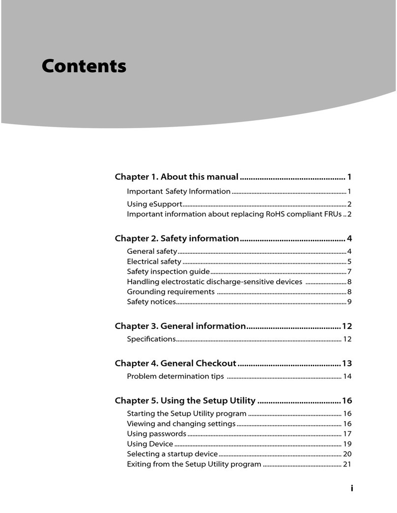
Contents
About this manual . . . . . . . . . . . . iii
Chapter . Safety information . . . . . .
General safety . . . . . . . . . . . . . . . . 1
Electrical safety . . . . . . . . . . . . . . . . 1
Safety ins ection guide . . . . . . . . . . . . . 2
Handling devices that are sensitive to electrostatic
discharge . . . . . . . . . . . . . . . . . . 3
Grounding requirements . . . . . . . . . . . . 4
Safety notices (multilingual translations) . . . . . . 4
Chapter 2. General checkout . . . . . 2
What to do first . . . . . . . . . . . . . . . 21
CRU list . . . . . . . . . . . . . . . . . . 22
Chapter 3. Identifying FRUs
(CRUs) . . . . . . . . . . . . . . . . . 23
Locate FRUs and CRUs . . . . . . . . . . . 23
Chapter 4. Removing a FRU or
CRU . . . . . . . . . . . . . . . . . . 29
Service tools . . . . . . . . . . . . . . . . 29
General guidelines. . . . . . . . . . . . . . 29
Remove the lower case . . . . . . . . . . . . 30
Remove the solid-state drive (SSD) late L . . . . 31
Remove the solid-state drive (SSD) late R . . . . 32
Remove the solid-state drive (SSD) . . . . . . . 33
Remove the battery ack . . . . . . . . . . . 34
Remove the memory module . . . . . . . . . 35
Remove the DC-in bracket . . . . . . . . . . 36
Remove the Wi-Fi card . . . . . . . . . . . . 36
Remove the CMOS battery . . . . . . . . . . 37
Remove the touch ad board cable . . . . . . . 38
Remove the C cover shield mylar . . . . . . . . 38
Remove the s eakers . . . . . . . . . . . . 39
Remove the thermal module . . . . . . . . . . 40
Remove the I/O board . . . . . . . . . . . . 41
Remove the system board and IO board cable . . . 42
Use a Golden Key U1 tool to flash-write key id
information . . . . . . . . . . . . . . . 44
Remove the finger rint module . . . . . . . . . 44
Remove the stri cover . . . . . . . . . . . . 46
Remove the hinge ca . . . . . . . . . . . . 48
Remove the LCD module . . . . . . . . . . . 49
Remove ceramic keyca s from the re laced
u er case(if installed by customers). . . . . 50
The keyca kit as a FRU. . . . . . . . . . 51
Disassemble the LCD module . . . . . . . . . 53
Remove the LCD bezel . . . . . . . . . . 53
Remove the hinge cover. . . . . . . . . . 54
Remove the LCD anel . . . . . . . . . . 55
Remove the EDP cable . . . . . . . . . . 56
Remove the camera bracket . . . . . . . . 56
Remove the micro hone rubbers . . . . . . 57
Remove the camera . . . . . . . . . . . 58
Remove the camera cable . . . . . . . . . 59
Remove the LCD cover . . . . . . . . . . 60
Appendix A. Label locations. . . . . . 6
Trademarks . . . . . . . . . . . . . . . . lxiii
© Co yright Lenovo 2022 i

