Note: To order replacement parts for your spreader, you need to
knowthe followinginformation:
A..Does your spreader have an epoxy-finish frame (white) or a
stainlesssteel frame(silver).
B.. Is it a standard wheel or a hi-wheel spreader. (The spreaders
can be identified by the numbers embossed on the side wall
of the tires. The standard wheel spreaders use a 4.10/3.50-4
tire while the hi-wheel spreaders use a 13x5.00-6 tire.)
C..If it is a standard wheel spreader, does it have an original
frame or a uni-frame. (Measure the vertical dimension
between the axle bearing mounts and the underside wheel
spreader, does it have an original frame or a uni-frame.
(Measure the vertical dimension between the axle bearing
mounts and the underside of the frame beneath the hopper. If
this dimension is 103/4" you have an original frame. If this
dimension is 123/4" you have a hi-wheel or uni-frame.)
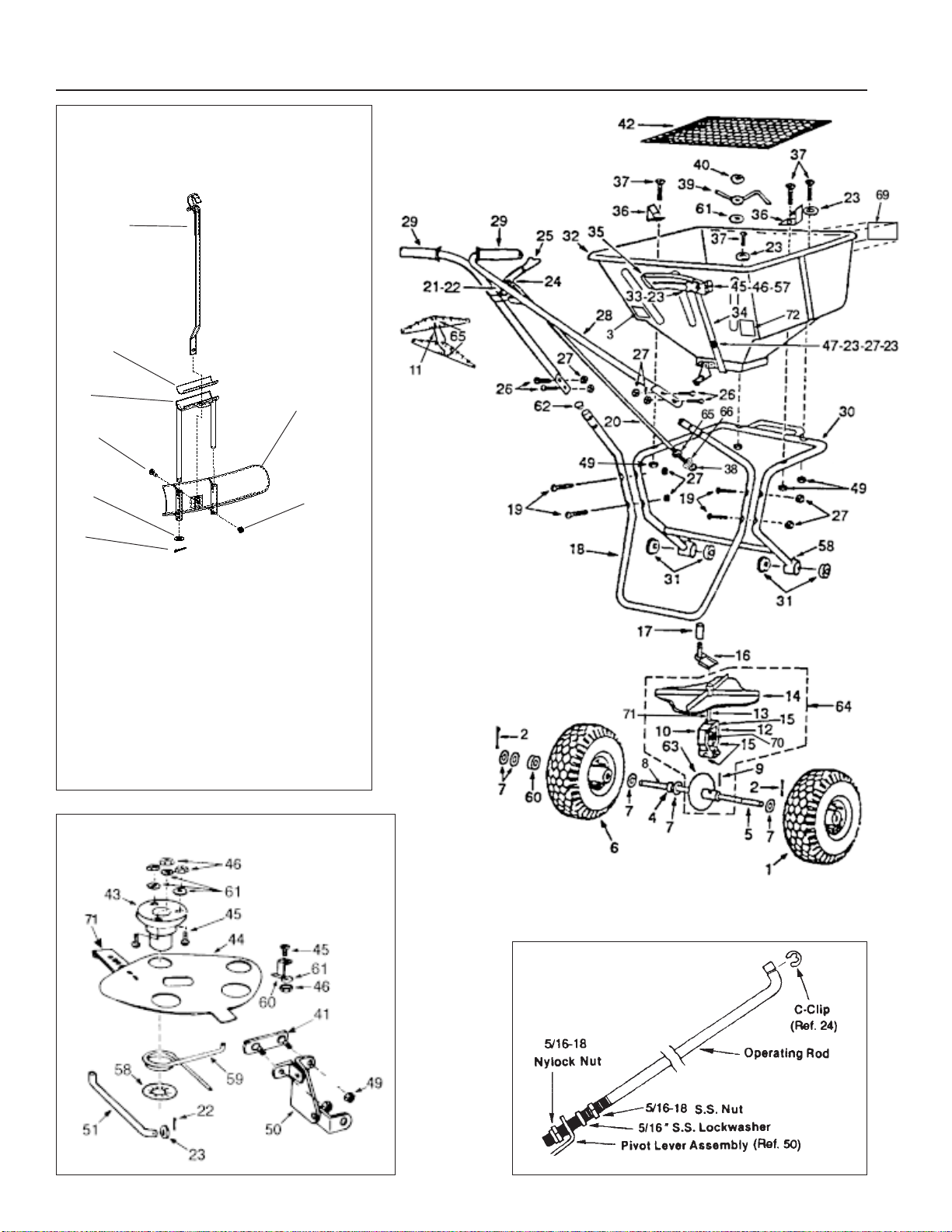
Rotary Spreaders — Parts List
2
Ref. Item No.
No. No. Description Used
1 060011 Drive Wheel, Steel - Standard ........................ 1
010048 Drive Wheel, Steel-Hi-Wheel.......................... 1
019789 Drive Wheel, Composite-Standard ................. 1
018901 Drive Wheel, Composite - Hi-Wheel............... 1
2 060012 Cotter Pin, 3/16 x 1-3/4, SS ............................ 2
3 011202 80 lb. Capacity Decal...................................... 1
4 020019 Axle Collar ...................................................... 1
5 020700 Axle ................................................................. 1
6 060016 Idler Wheel, Steel-Standard ........................... 1
010047 Idler Wheel, Steel - Hi-Wheel .........................1
018900 Idler Wheel, Composite - Standard ................ 1
019790 Idler Wheel, Composite-Hi Wheel .................. 1
7 060017 Spacer Washer, SS ........................................8
8 010985 Set Screw ....................................................... 1
9 060019 Roll Pin, 5/32 x 1-/14, SS ............................... 1
10 064000
Gear Support Assembly (Incl. 3 ea. Ref.15)w/
Fittings ............................................................
3
11 009941 Chain .............................................................. 1
12 060022 Roll Pin, 1/8 x 7/8, SS.....................................1
13 009004 Impeller Shaft (8-1/2" long)............................. 1
060023 Impeller Shaft (6-7/8" long) and Roll Pin
1/8 x 7/8, SS (Replacement for standard
wheel spreaders with original frames. See
Note C above.)................................................ 1
14 030317 Impeller ........................................................... 1
15 060095 Grease Fitting (Press-In Type) ....................... 3
16 030322 Agitator Arm and Shaft Assembly................... 1
17 060027 Bearing, Agitator Shaft ................................... 1
18 009188 Leg, Stainless Steel (Incl. 2 ea. Ref. 62) ........1
19 060029 Mach.Screw,1/4-20 x 2
Pan Phil. Hd., SS ............................................ 4
20 010087 Operating Lever Rod ...................................... 1
060030 Operating Lever Rod (29-1/2" long), Nut,
Locknut & Lock Washer Ass’y (Replace-
ment for standard wheel spreaders with
original frames. See Note C above.) .............. 1
21 060031 Clevis Pin, 1/4" x 1/2", SS .............................. 1
22 060032 Cotter Pin, 3/32 x 1/2, SS ...............................2
23 060033 Flat Washer1/4" SAE, SS ...............................5
24 010171 C-Clip .............................................................. 1
25 060034 Operating Lever and Rubber Handle ............. 1
26 060047 Cap Screw 1/4-20 x 1-1/2 Hex Hd., SS .......... 4
27 060036 Hex Nut 1/4-20 Nylock, SS............................. 9
28 060037 Handle, Epoxy Finish...................................... 1
020270 Handle, Stainless Steel .................................. 1
29 060038 Flanged Grip, Black, 3/4 x 4 ........................... 2
30 013206 Uni-Frame, Epoxy Finish (Incl. 4 ea.
Ref. Item No.
No. No. Description Used
Ref. 31 and 2 ea. Ref. 58.) .............................1
020556 Uni-Frame, Stainless Steel ............................1
077791 Frame, Epoxy Finish (Replacement Kit for
standard wheel spreaders with original
frames. See Note C above. (Incl. 4 ea. Ref.
31 & 2 ea. Ref. 58).......................................... 1
073947 Frame, Stainless Steel (Replacement Kit
for standard wheel spreaders with original
frames. See Note C above. Incl. 4 ea. Ref.
31 & 2 ea. Ref. 58).......................................... 1
31 060041 Axle Bearing ................................................... 1
018963 Axle Bushing, Composite ............................... 4
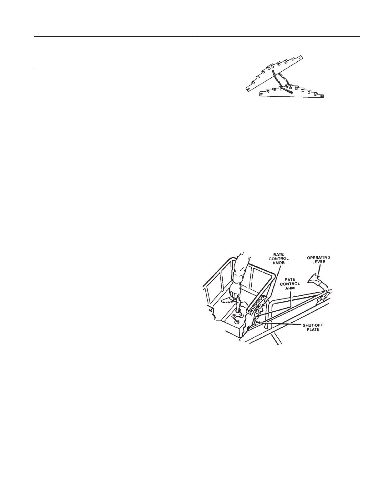
32 060042 Hopper ............................................................ 1
33 060043 Rate Control Knob ..........................................1
34 060044 Rate Control Arm ............................................ 1
35 060045 Rate Control Plate .......................................... 1
36 060046 Screen Clip, SS .............................................. 2
37 031167 Hex Cap Screw, 1/4-20 x 1-1/2
........................................................................ 4
38 060071 Hex Nut 5/16 x 18 ........................................... 1
39 060049 Agitator Arm .................................................... 1
40 060050 Agitator Clip .................................................... 1
41 704539 Plate, Two-Hole, Weldment ............................ 1
42 060052 Screen ............................................................ 1
43 060053 Shaft Support, Impeller ................................... 1
44 020491 Shutoff Plate Remote...................................... 1
45 031686 Mach. Screw, #8-32 x 1/2
Pan Phil. Hd., SS ............................................ 7
46 060056 Hex Nut, #8-32, SS......................................... 7
47 060057 Mach. Screw, 1/4-20 x 7/8
Pan Phil. Hd., SS ............................................ 1
48 – – –
49 060036 Hex Nut, 1/4-20, SS........................................ 6
50 060060 Pivot Lever Assembly ..................................... 1
51 060061 Pivot Lever Rod ..............................................1
52 060072 Nylock Nut ...................................................... 1
53 060073 Locking Washer .............................................. 1
54 060064 Spring Clip 3/4, SS ......................................... 1
55 060065 Rate Control Spring ........................................1
56 060066 Shutoff Plate Clip ............................................ 2
57 060083 Lock Washer #8 Star, SS ............................... 7
58 060064 Spring Clip 3/4, SS ......................................... 1
59 060065 Rate Control Spring ........................................1
60 078076 Spacer ............................................................ 1
61 005530 Flat Nylon Washer ..........................................1
62 020913 Plug, Plastic (Stainless Frame) ...................... 2
63 060013 Bevel Gear ...................................................... 1
64 020074 Impeller and Gear Assembly
(Incl. 1 ea. Ref. 10, 13, 14 & 63)..................... 1
020054 Impeller and Gear Assembly (Replace-
ment for standard wheel spreaders with
original frames. See Note C above. incl
1 ea. Ref. 10, 13, 14 & 63............................... 1
65 009742 Calibration Gauges-Odd ................................. 1
009746 Calibration Gauges-Even ............................... 1
66 700128 Nylon Washer ................................................. 2
67 016354 Carton (Box) ................................................... 1
68 020492 Slide Lever...................................................... 1
69 706895 “Lesco” Decal .................................................1
70 060021 Pinion Gear ....................................................1
71 060069 Roll Pin ...........................................................1
72 090006 “USA” Decal ................................................... 1
Optional Accessories for Rotary Spreaders
060087 Jet Action Deflector Ass'y. .............................. 1
060099 Hopper Cover (not shown) ............................. 1
009277 Spreader Gear Cover Ass’y. (not shown)....... 1
*Indicates this part can replace a similar part on a Scotts RX-7
spreader.