Leutert MUDTEST 7100.11.00000 User manual

MUDTEST Sp. z o.o., www.mudtest.com, [email protected]
API Filter Press
Instruction Manual
Filtration
The API lter press is used to analyze ltration behavior and wall
cake building characteristics of drilling uids and cement slurries..

2 API Filter Press
The manufacturer
MUDTEST Sp. z o.o.
Chełmońskiego 77, 32-500 Chrzanów / Polen
hereby declares that the following product:
Name of product API Filter Press
Drawing number 7100.11.00000
complies with the provisions of the guidelines identied below, including those at the time of the declaration
applicable changes.
¨Pressure Equipment Directive 2014/68/EU
The lter press is classied as pressure equipment according to Article 4 Paragraph 3 of the Pressure Equip-
ment Directive and has been designed and manufactured in accordance with good engineering practice.
The following harmonized standards were applied:
¨ ISO 10414-1:2008
Petroleum and natural gas industries — Field testing of drilling uids — Part 1: Water-based uids
The following national standards were applied:
¨API RP 13B-1
Petroleum and natural gas industries — Field testing of drilling uids — Part 1: Water-based uids
¨ DIN 4127
Earthworks and foundation engineering – Test methods for supporting uids used in the construction of
diaphragm walls and their constituent products
Adendorf, 01.08.2023
Place and date Management representative for declarations of conformity
EU Declaration of conformity

API Filter Press 3
Description
The API lter press is used to analyze ltration behavior and wall cake build-
ing characteristics of drilling uids and cement slurries. Their stability is
based on uid loss and may be determined by measuring and describing the
lter cake.
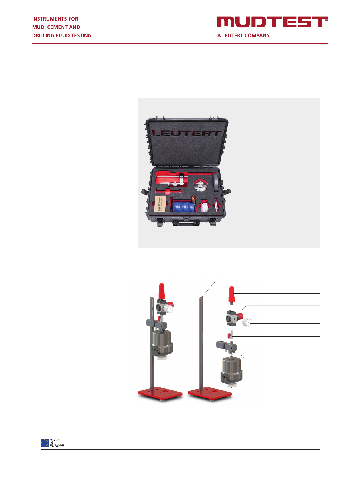
The components of the lter press are: A cell body to hold the mud sample,
a base cap c/w drain tube to discharge ltrate into a graduated cylinder, a
stand, a cell support including a pressure regulator with gauge, a CO2 car-
tridge holder or an air hose. The base cap holds an exchangeable mesh on
which a 3½” (90 mm) sheet of lter paper can be placed. This corresponds
with a ltration area of 7.1 ± 0.1 in2 (4,580 ± 60 mm2) recommended by the
American Petroleum Institute (API).
Before the test a sheet of lter paper is placed on the mesh in the base cap.
The cell body of the lter press is lled with mud or cement and the cell
is closed with the base cap. A pressure of 100 psi is applied to the cell by
piercing the CO2 cartridge or by compressed air from a bottle or compressor.
Filtrate is driven through lter paper and the outlet in the base cap and col-
lected by means of a graduated measuring cylinder. After a time period of 30
minutes the amount of discharged uid may be recorded and the lter cake
that has formed on the lter paper is measured and described.
As an alternative to CO2 cartridges or compressed air, the ltration pressure
may be generated in a U-shape hydraulic assembly. On one side of the U
there is a vertically aligned cylinder with a piston acting on a water column.
A dead weight is resting on the piston, pushing the water into the other side
of the U and compressing the air above the water column, thus creating the
ltration pressure in the lter press cell. This lter press model does not need
a pressure regulator nor an external pressure source.
The MUDTEST lter press complies with the requirements of API RP 13B-1 or
the corresponding international standard ISO 10414 for eld testing of drill-
ing uids. The requirements of the German standard DIN 4127 for the test
procedure for supporting uids in diaphragm wall construction are also met.
The lter press falls within the scope of the European Pressure Equipment
Directive 2014/68 / EU. Therefore, the corresponding conformity assessment
procedure was carried out and the CE marking was attached.

4 API Filter Press
Technical Specications
Max. test pressure : 10 bar | 145 psi
Medium temperature : 20°C ± 2°C | 68°F ± 2°F
Dimensions :
200 x 500 x 230 mm | 7.87 x 19.68 x 9.0 in
Weight : ca. 5.5 kg | 12.13 lbs
Material test cell assembly : stainless steel
Volume test cell assembly : 316 ml
Cell inside diameter : Ø 76.2 mm | 3 inch
Cell inside hight : >64 mm | 2.5 inch
Filtration area : 45.8 cm2 | 7.1 inch2
Diameter lter paper : 90 mm | 3.54 inch

API Filter Press 5
Order Information
Filter Press / 7100.11.00000
Graduated cylinder 10 ml 3000.00.00010
Seal kit 7100.11.02002
Filter paper 7100.11.02205
Spiral air hose 7100.11.07001
CO2cartridge 7100.11.06006
Carriing case c/w form insert 7100.11.09100
CO2cartridge holder 7100.11.06000
Pressure Gauge
7100.11.04001
Stand 7100.11.01000
Pressure regulator 7100.11.04002
Ball valve 7100.11.05000
Drilling-uid cell 7100.11.02000
Cell support 7100.11.03000
O-Ring 7100.11.03005

6 API Filter Press
External circlip 7100.11.02005
O-Ring 7100.11.02004
T-Coupling 7100.11.02003
Cell 7100.11.02300
Gasket 7100.11.02206
Filter paper 7100.11.02205
Countersunk screw 7100.11.02208
Screen 7100.11.02204
Lid c/w drain tube 7100.11.02200
O-Ring 7100.11.02207
Clamp 7100.11.02101
Knurled screw 7100.11.02103
Hexagon nut self-locking 1000.52.00002
Puncturing head assembly 7100.11.06100
Gasket (not shown) 7100.11.06103
CO2Cartrige (must be ordered seperately) 7100.11.06006
Barrel for CO2cartridge 7100.11.06002
CO2 Cartridge holder assembly / 7100.11.06000
Drilling-uid cell assembly / 7100.11.02000

API Filter Press 7
Operating procedure
1. Unscrew and remove the barrel for CO2 cartridge.
2. Make sure that the pressure regulator is closed.
3. Insert a CO2 cartridge in the barrel and tighten it carefully
4. with approximately three turns.
NOTICE: The CO2 cartridges must not be opened yet, CO2
should not exhaust!
5. Remove the drilling-uid cell assembly from the T-groove.
6. Turn the knurled screw counter clockwise to drive the lid out of the cell
until the o-ring becomes visible.
7. Pull out the lid from the cell by twisting the assembly and put it
aside. Assure that all components are clean and dry and that the
o-ring is not twisted or damaged.
8. Remove the gasket.
9. Turn the drilling-uid cell assembly upside down and close the hole
in the T-coupling with a nger tip. Pour the freshly stirred sample
uid into the cell, leaving 13 mm of empty space at the top.
10. Clean the area where the gasket will rest and return the gasket.
11. Place a lter paper on top of the gasket.
12. Return the lid and lock the clamp by twisting and tighten the knur-
led screw.
13. Turn around the test cell assembly, close the drain tube with a n-
ger tip, and push the cell back into the T-groove.
14. Place a dry graduated cylinder below the drip tube to collect the
ltrate.
15. Tighten the barrel fully to release CO2.
16. Adjust the regulator so that a pressure of 100 psi ± 5 psi is applied
within 30 s or less. The test period beginns at the time of pressure
application.
17. At the end of 30 min, measure the volume of ltrate collected. Shut
off the ow through the pressure regulator and open the relief valve

8 API Filter Press
carefully. The time interval, if other than 30 min, shall be reported.
NOTICE: The duration and test pressure vary depending on
which standard is being followed. While API requires a test pres-
sure of 100 PSI for a duration of 30 minutes, DIN 4127 requires a
test pressure of 7 bar for only 7.5 minutes.
18. Report the volume of ltrate in millilitres (to the nearest 0, 1 ml)
and the initial drilling uid temperature in degrees Celsius (degrees
Fahrenheit). Save the ltrate for chemical analysis.
19. Remove the cell from the frame, rst making certain that all pres-
sure has been relieved. Carefully save the lter paper with a mini-
mum of disturbance to the cake, disassemble the cell and discard
the drilling uid.
Wash the lter cake on the paper with a gentle stream of water.
20. Measure and report the thickness of the lter cake, to the nearest
millimetre (1/32 in).
21. Although cake descriptions are subjective, such notations as hard,
soft, tough, rubbery, rm, etc., can convey important information of
cake quality.
Subject to change without notice. Issued 08/2023
Table of contents