Leuze CSL 710 User manual

CSL 710
Lichtvorhänge CSL 710
CSL 710 light curtains
Rideaux lumineux CSL 710
Cortine fotoelettriche CSL 710
Cortinas ópticas CSL 710
Cortinas de luz CSL 710
光幕 CSL 710
Leuze electronic GmbH + Co. KG
We reserve the right to make changes – 2018/05 – 50140028
www.leuze.com•

1Bildteil
1
A
B
C
D
E
F
2

2
3

3
PWR IN/OUT
X1 X 2X3
12
3
4
AB
CD
E
4

Sicherheit
Der vorliegende Lichtvorhang ist unter Beachtung der geltenden Sicherheitsnor-
men entwickelt, gefertigt und geprüft worden.
Bestimmungsgemäße Verwendung
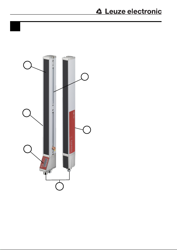
Lichtvorhänge der Baureihe CSL 710 sind optoelektronische Sensoren zur opti-
schen und berührungslosen Erfassung oder Vermessung von Objekten.
Einsatzgebiete
Die Lichtvorhänge der Baureihe CSL 710 sind insbesondere für folgende Einsatz-
gebiete konzipiert:
– Höhen-/Lage-Kontrolle
– Überstandkontrolle
– Zählen
Vorhersehbare Fehlanwendung
Eine andere als die unter „Bestimmungsgemäße Verwendung“ festgelegte oder
eine darüber hinausgehende Verwendung gilt als nicht bestimmungsgemäß. Un-
zulässig ist die Verwendung des Geräts insbesondere in folgenden Fällen:
– in Räumen mit explosiver Atmosphäre (außer Ex Varianten)
– in Sicherheitsrelevanten Schaltungen
– zu medizinischen Zwecken
HINWEIS
Nehmen Sie keine Eingriffe oder Änderungen am Gerät vor!
Befähigte Personen
Anschluss, Montage, Inbetriebnahme und Einstellung des Geräts dürfen nur durch
befähigte Personen durchgeführt werden.
Voraussetzungen für befähigte Personen:
– Sie verfügen über eine geeignete technische Ausbildung.
– Sie kennen die Regeln und Vorschriften zu Arbeitsschutz und Arbeitssicher-
heit.
– Sie kennen die Original-Betriebsanleitung des Geräts.
– Sie wurden vom Verantwortlichen in die Montage und Bedienung des Geräts
eingewiesen.
Elektrofachkräfte
Elektrische Arbeiten dürfen nur von Elektrofachkräften durchgeführt werden.
Elektrofachkräfte sind aufgrund ihrer fachlichen Ausbildung, Kenntnisse und Er-
fahrungen sowie Kenntnis der einschlägigen Normen und Bestimmungen in der
Lage, Arbeiten an elektrischen Anlagen auszuführen und mögliche Gefahren
selbstständig zu erkennen.
In Deutschland müssen Elektrofachkräfte die Bestimmungen der Unfallverhü-
tungsvorschrift DGUV Vorschrift3 erfüllen (z.B. Elektroinstallateur-Meister). In
anderen Ländern gelten entsprechende Vorschriften, die zu beachten sind.
5
DE

Haftungsausschluss
Die LeuzeelectronicGmbH+Co.KG haftet nicht in folgenden Fällen:
– Das Gerät wird nicht bestimmungsgemäß verwendet.
– Vernünftigerweise vorhersehbare Fehlanwendungen werden nicht berück-
sichtigt.
– Montage und elektrischer Anschluss werden nicht sachkundig durchgeführt.
– Veränderungen (z.B. bauliche) am Gerät werden vorgenommen.
Übersicht
1
A Messfeld
B Befestigungsschiene
C Sender
D M12-Anschlusseinheit
E Bedienfeld mit Display
F Empfänger
Typenschlüssel
CSL710-T05-1920.A-M12
CSL710-R05-1920.A/L-M12
Funktionsprinzip
CSL Schaltender Lichtvorhang
Baureihe
710 – Baureihe: 710
– Reichweite: 0,3m…7m
– Grenzreichweite: 0,2m…9m
– Zykluszeit: 30µs pro Strahl
– Display
T– Sender (Transmitter)
R– Empfänger (Receiver)
Strahlabstand
05 5mm
10 10mm
20 20mm
40 40mm
6
DE

Messfeldlänge
xxx Messfeldlänge [mm], abhängig vom Strahlabstand
Ausstattung
A Steckabgang axial
Interface
L IO-Link
Elektrischer Anschluss
M12 M12-Rundsteckverbinder
Inbetriebnahme
Montage
HINWEIS
Achten Sie darauf, dass sich keine reflektierenden Flächen im Umkreis
befinden.
Die Lichtvorhänge können mit dem Standardzubehör auf drei verschiedene Me-
thoden befestigt werden:
– Mit der T-Nut inklusive Nutenstein können Sie den Lichtvorhang seitlich starr
befestigen.
– Die Drehhalterung wird auf der Ober- und Unterseite des Lichtvorhanges be-
festigt und erlaubt eine Drehung von 360°.
– Die optionale Schwenkhalterung wird seitlich in die T-Nut des Lichtvorhangs
eingesetzt und erlaubt eine Verdrehung von +/-8°.
– Weitere Informationen finden Sie in der Betriebsanleitung im Kapitel „Monta-
ge“.
Anschlussbelegung
Siehe "Elektrischer Anschluss"
Konfiguration
Sie können den Lichtvorhang direkt über die Bedientasten am Empfänger konfigu-
rieren. Das Display zeigt ihnen die einzelnen Menüpunkte an, die je nach Konfigu-
ration ein-/ausgeblendet sind.
Komfortabler können Sie die Lichtvorhänge der Baureihe CSL 710 über die IO-
Link-Schnittstelle konfigurieren. Dazu empfehlen wir unseren IO-Link-Master der
MD-Serie.
Die Konfiguration findet dann über die Konfigurations-Software
Sensor Studio
statt.
7
DE

Software herunterladen
ÄRufen Sie die Leuze Homepage auf: www.leuze.com
ÄGeben Sie als Suchbegriff die Typenbezeichnung oder die Artikelnummer
des Geräts ein.
ÄDie Konfigurations-Software finden Sie auf der Produktseite des Geräts unter
der Registerkarte
Downloads
.
Um die passenden IODD Profile vorliegen zu haben, sollten Sie ebenfalls die
IODD-Dateien sowie die
IO-Link Device Collection
herunterladen.
Weitere Informationen finden Sie in der Betriebsanleitung.
Technische Daten
Siehe Betriebsanleitung, Kapitel „Technische Daten“
Technische Zeichnungen
2
CSL710 mit axialem Steckverbinderabgang
Alle Maße in mm
A Strahlabstand
B Messfeldlänge
C PWR IN/Digital IO und IO-Link-Schnittstelle
D Verbindung zum Sender
E Verbindung zum Empfänger
F Gewinde M6
G Befestigungsnut
L Profillänge
R Empfänger
T Sender
Y Gerät mit Strahlabstand 5 mm; Y = 2,5 mm
Gerät mit Strahlabstand 10, 20, 40 mm; Y = 5 mm
Elektrischer Anschluss
Die Lichtvorhänge der Baureihe CSL710 bedienen die folgende Schnittstelle:
– IO-Link
Die Sender verfügen über einen M12-Stecker.
Die Empfänger verfügen über zwei M12-Stecker.
8
DE

CSL 710 mit IO-Link-Schnittstelle
3
A Receiver (R) = Empfänger
B Transmitter (T) = Sender
C Anschlussleitung (M12-Buchse, 8-polig)
D Synchronisationsleitung (M12-Stecker/Buchse, 5-polig)
E PWR IN/OUT
Anschließen
ÄSchließen Sie den X2-Anschluss mit der Synchronisationsleitung an den X3-
Anschluss an.
ÄSchließen Sie den X1-Anschluss mit der Anschlussleitung an die Spannungs-
versorgung und die Steuerung an.
PIN X1 – Logik und Power am Empfänger
1 VIN: +24V DC Versorgungsspannung
2 IO 1: Ein-/Ausgang (konfigurierbar)
Werkeinstellungen: Teacheingang (Teach-In)
3 GND: Masse (0V)
4 C/Q: IO-Link Kommunikation
5 IO 2: Ein-/Ausgang (konfigurierbar)
Werkeinstellungen: Triggereingang (Trigger-In)
6 IO 3: Ein-/Ausgang (konfigurierbar)
7 IO 4: Ein-/Ausgang (konfigurierbar)
8 GND: Masse (0V)
PIN X2/X3 – Sender bzw. Empfänger
1 SHD: FE-Funktionserde, Schirm
2 VIN: +24V DC Versorgungsspannung
3 GND: Masse (0V)
4 RS 485 Tx+: Synchronisation
5 RS 485 Tx-: Synchronisation
9
DE

Safety
This light curtain was developed, manufactured and tested in line with the applica-
ble safety standards.
Intended use
Light curtains of the CSL 710 series are optoelectronic sensors for optical and
contactless detection or measurement of objects.
Areas of application
The light curtains of the CSL 710 series are especially designed for the following
areas of application:
– Height/position detection
– Projection monitoring
– Counting
Foreseeable misuse
Any use other than that defined under "Intended use" or which goes beyond that
use is considered improper use. In particular, use of the device is not permitted in
the following cases:
– in rooms with explosive atmospheres (with exception of Ex models)
– in circuits which are relevant to safety
– for medical purposes
NOTICE
Do not carry out modifications or otherwise interfere with the device!
Competent persons
Connection, mounting, commissioning and adjustment of the device must only be
carried out by competent persons.
Prerequisites for competent persons:
– They have a suitable technical education.
– They are familiar with the rules and regulations for occupational safety and
safety at work.
– They are familiar with the original operating instructions of the device.
– They have been instructed by the responsible person on the mounting and
operation of the device.
Certified electricians
Electrical work must be carried out by a certified electrician.
Due to their technical training, knowledge and experience as well as their familiar-
ity with relevant standards and regulations, certified electricians are able to per-
form work on electrical systems and independently detect possible dangers.
In Germany, certified electricians must fulfill the requirements of accident-preven-
tion regulations DGUV Regulation3 (e.g. electrician foreman). In other countries,
there are respective regulations that must be observed.
10
EN

Disclaimer
LeuzeelectronicGmbH+Co.KG is not liable in the following cases:
– The device is not being used properly.
– Reasonably foreseeable misuse is not taken into account.
– Mounting and electrical connection are not properly performed.
– Changes (e.g., constructional) are made to the device.
Overview
1
A Measurement field
B Fixing rails
C Transmitter
D M12 connection unit
E Control panel with display
F Receiver
Part number code
CSL710-T05-1920.A-M12
CSL710-R05-1920.A/L-M12
Operating prin-
ciple
CSL Switching light curtain
Series
710 – Series: 710
– Operating range: 0.3m…7m
– Operating range limit: 0.2m…9m
– Cycle time: 30µs per beam
– Display
T– Transmitter
R– Receiver
11
EN

Beam spacing
05 5mm
10 10mm
20 20mm
40 40mm
Measurement field length
xxx Measurement field length [mm], dependent on beam spacing
Equipment
A Plug outlet, axial
Interface
L IO-Link
Electrical connection
M12 M12 connector
Commissioning
Mounting
NOTICE
Make sure there are no reflecting surfaces in the vicinity.
The light curtains can be fixed with three different methods with the standard ac-
cessories:
– You can mount the light curtain so it is laterally fixed using the T-groove and
sliding block.
– The swivel mount is fixed at the top and bottom of the light curtain and per-
mits 360° turning.
– The optional swiveling mounting bracket is used laterally in the T-groove of
the light curtain and permits +/-8° turning.
– More information can be found in the chapter "Mounting" of the operating in-
structions.
Pin assignment
See "Electrical connection"
Configuration
You can configure the light curtain directly using the control buttons on the re-
ceiver. The display shows you the individual menu items, which are displayed/hid-
den depending on the configuration.
12
EN

More conveniently, you can configure the light curtains of the CSL 710 series us-
ing the IO-Link interface. We recommend our IO-Link master from the MD series
in this regard.
Configuration is performed using the
SensorStudio
configuration software.
Download software
ÄCall up the Leuze home page: www.leuze.com
ÄEnter the type designation or part number of the device as the search term.
ÄThe configuration software can be found on the product page for the device
under the
Downloads
tab.
In order to have the IODD profiles available, you should also download the IODD
files, as well as the
IO-Link Device Collection
.
More information can be found in the operating instructions.
Technical data
See chapter "Technical data" of the operating instructions
Technical drawings
2
CSL710 with axial connector outlet
All dimensions in mm
A Beam spacing
B Measurement field length
C PWR IN/Digital IO and IO-Link interface
D Connection to transmitter
E Connection to receiver
F M6 thread
G Fastening groove
L Profile length
R Receiver
T Transmitter
Y Devices with beam spacing 5mm; Y=2.5mm
Devices with beam spacing 10, 20, 40mm; Y=5mm
Electrical connection
The light curtains of the CSL710 series operate the following interface:
– IO-Link
The transmitters have an M12 connector.
The receivers have two M12 connectors.
13
EN

CSL 710 with IO-Link interface
3
A Receiver (R)
B Transmitter (T)
C Connection cable (M12 socket, 8-pin)
D Synchronization cable (M12 plug/socket, 5-pin)
E PWR IN/OUT
Connect
ÄConnect connection X2 to connection X3 using the appropriate synchroniza-
tion cable.
ÄConnect connection X1 to the voltage supply and the control using the appro-
priate connection cable.
PIN X1 - Logic and power on the receiver
1 VIN: +24V DC supply voltage
2 IO 1: input/output (configurable)
Factory settings: teach input (Teach In)
3 GND: ground (0V)
4 C/Q: IO-Link communication
5 IO 2: input/output (configurable)
Factory settings: Trigger input (Trigger In)
6 IO 3: input/output (configurable)
7 IO 4: input/output (configurable)
8 GND: ground (0V)
PIN X2/X3 - Transmitter and receiver
1 SHD: FE functional earth, shield
2 VIN: +24V DC supply voltage
3 GND: ground (0V)
4 RS 485 Tx+: synchronization
5 RS 485 Tx-: synchronization
14
EN

Sécurité
Le présent rideau lumineux a été développé, produit et testé dans le respect des
normes de sécurité en vigueur.
Utilisation conforme
Les rideaux lumineux de la série CSL 710 sont des capteurs photoélectriques
pour la détection optique sans contact ou la mesure d'objets.
Domaines d'application
Les rideaux lumineux de la série CSL 710 se prêtent tout particulièrement aux ap-
plications suivantes:
– Contrôle de hauteur et de position
– Contrôle de dépassement
– Comptage
Emplois inadéquats prévisibles
Toute utilisation ne répondant pas aux critères énoncés au paragraphe «Utilisa-
tion conforme» ou allant au-delà de ces critères n'est pas conforme. En particu-
lier, les utilisations suivantes de l'appareil ne sont pas permises:
– dans des pièces à environnement explosif (sauf variantes Ex)
– dans des câblages de haute sécurité
– à des fins médicales
AVIS
N'intervenez pas sur l'appareil et ne le modifiez pas!
Personnes qualifiées
Seules des personnes qualifiées sont autorisées à effectuer le raccordement, le
montage, la mise en service et le réglage de l'appareil.
Conditions pour les personnes qualifiées:
– Elles ont bénéficié d'une formation technique appropriée.
– Elles connaissent les règles et dispositions applicables en matière de pro-
tection et de sécurité au travail.
– Elles connaissent le manuel d'utilisation original de l'appareil.
– Elles ont été instruites par le responsable en ce qui concerne le montage et
la manipulation de l'appareil.
Personnel qualifié en électrotechnique
Les travaux électriques ne doivent être réalisés que par des experts en électro-
technique.
Les experts en électrotechnique sont des personnes qui disposent d'une forma-
tion spécialisée, d'une expérience et de connaissances suffisantes des normes et
dispositions applicables pour être en mesure de travailler sur des installations
électriques et de reconnaître par elles-mêmes les dangers potentiels.
15
FR

En Allemagne, les experts en électrotechnique doivent satisfaire aux dispositions
du règlement de prévention des accidents de la DGUV, clause 3 (p.ex. diplôme
d'installateur-électricien). Dans les autres pays, les dispositions correspondantes
en vigueur doivent être respectées.
Exclusion de responsabilité
LeuzeelectronicGmbH+Co.KG ne peut pas être tenue responsable dans les
cas suivants:
– L'appareil n'est pas utilisé de façon conforme.
– Les emplois inadéquats raisonnablement prévisibles ne sont pas pris en
compte.
– Le montage et le raccordement électrique ne sont pas réalisés par un per-
sonnel compétent.
– Des modifications (p.ex. de construction) sont apportées à l'appareil.
Récapitulatif
1
A Champ de mesure
B Rail de fixation
C Émetteur
D Unité de branchement M12
E Panneau de commande avec écran
F Récepteur
Codes de désignation
CSL710-T05-1920.A-M12
CSL710-R05-1920.A/L-M12
Principe de
fonctionnement
CSL Rideau lumineux de commutation
Série
710 – Série: 710
– Portée: 0,3m…7m
– Portée limite: 0,2m…9m
– Durée du cycle: 30µs par faisceau
– Écran
T– Émetteur (Transmitter)
R– Récepteur (Receiver)
16
FR

Intervalle entre les faisceaux
05 5mm
10 10mm
20 20mm
40 40mm
Profondeur de mesure
xxx Profondeur de mesure [mm], selon l'intervalle entre les fais-
ceaux
Équipement
A Sortie de prise axiale
Interface
L IO-Link
Raccordement électrique
M12 Connecteur M12
Mise en service
Montage
AVIS
Veillez à ce qu'aucune surface réfléchissante ne se trouve aux alen-
tours.
Les rideaux lumineux peuvent être fixés de trois manières différentes à l'aide d'ac-
cessoires standard:
– La rainure en T avec coulisseau permet de fixer le rideau lumineux de ma-
nière rigide sur le côté.
– Le support tournant fixé en haut et en bas du rideau lumineux permet la ro-
tation sur 360°.
– Le support pivotant en option est mis en place sur le côté dans la rainure en
T du rideau lumineux et permet de le faire pivoter de +/-8°.
– Vous trouverez plus d'informations au chapitre «Montage» du manuel d'uti-
lisation.
Affectation des broches
Voir "Raccordement électrique"
17
FR

Configuration
Il est possible de configurer le rideau lumineux directement sur le récepteur au
moyen des touches de commande. Vous verrez à l'écran les différentes options
de menu qui sont affichées ou masquées selon la configuration.
L'interface IO-Link permet de configurer les rideaux lumineux CSL 710 de manière
plus conviviale. Pour cela, nous recommandons d'employer un maître IO-Link de
la série MD.
La configuration est réalisée à l'aide du logiciel de configuration
SensorStudio
.
Télécharger le logiciel
ÄOuvrez le site internet de Leuze: www.leuze.com
ÄEntrez le code de désignation ou le numéro d'article de l'appareil comme cri-
tère de recherche.
ÄLe logiciel de configuration se trouve sous l'onglet
Téléchargements
de la
page consacrée à l'appareil.
Pour disposer des profils IODD adaptés, il est conseillé de charger également les
fichiers IODD ainsi que
IO-Link Device Collection
.
Vous trouverez plus d'informations dans le manuel d'utilisation.
Caractéristiques techniques
Voir le manuel d'utilisation, chapitre «Caractéristiques techniques»
Dessins techniques
2
CSL710 avec sortie axiale du connecteur
Toutes les mesures en mm
A Intervalle entre les faisceaux
B Profondeur de mesure
C PWR IN/ES numérique et interface IO-Link
D Liaison vers l'émetteur
E Liaison vers le récepteur
F Filetage M6
G Encoche de fixation
L Longueur du profilé
R Récepteur
T Émetteur
Y Appareil avec intervalle entre les faisceaux de 5mm: Y=2,5mm
Appareil avec intervalle entre les faisceaux de 10, 20, 40mm: Y=5mm
18
FR

Raccordement électrique
Les rideaux lumineux de la série CSL710 sont compatibles avec l'interface sui-
vante:
– IO-Link
Les émetteurs disposent d'un connecteur M12.
Les récepteurs disposent de deux connecteurs M12.
CSL 710 avec interface IO-Link
3
A Receiver (R)=Récepteur
B Transmitter (T)=Émetteur
C Câble de raccordement (prise femelle M12, 8pôles)
D Câble de synchronisation (prises mâle/femelle M12, 5pôles)
E PWR IN/OUT
Raccordement
ÄRaccordez la connexion X2 avec câble de synchronisation à la connexion X3
an.
ÄRaccordez la connexion X1 avec câble de raccordement à l'alimentation en
tension et à la commande.
Bro-
che
X1 - Logique et Power sur le récepteur
1 VIN: tension d'alimentation +24VCC
2 ES1: entrée/sortie (configurable)
Réglage d'usine: entrée d'apprentissage (Teach In)
3 GND: masse (0V)
4 C/Q: communication IO-Link
5 ES2: entrée/sortie (configurable)
Réglage d'usine: entrée de déclenchement (Trigger-In)
6 ES3: entrée/sortie (configurable)
7 ES4: entrée/sortie (configurable)
8 GND: masse (0V)
19
FR

Bro-
che
X2/X3 - Émetteur / récepteur
1 SHD: terre de fonction FE, blindage
2 VIN: tension d'alimentation +24VCC
3 GND: masse (0V)
4 RS 485 Tx+: synchronisation
5 RS 485 Tx-: synchronisation
20
FR
Table of contents
Languages:
Other Leuze Lighting Equipment manuals
Popular Lighting Equipment manuals by other brands

Laserworld
Laserworld CS-8000RGB FX MK2 manual

Lucci LEDlux
Lucci LEDlux 250870 installation instructions

Lightolier
Lightolier Calculite 8098 specification

Luxor
Luxor X S1 Installation instruction

MJ LED LIGHTNING
MJ LED LIGHTNING WIRELESS BATTERY PAR 910 user manual

Costco
Costco JF5687 Assembly instructions