Level GB 060 3xx User manual

Programmable GSM Automaton
Universal GSM Communicator
InstallationandUser Guide
LEVEL
GB 060 3xx,GB 060 5xx

2

3
Dear Customer,
Congratulations on purchasing GB060.You have purchasedatop-qualityand state-
of-the–art product.
GB060combines, inaunique way,aprogrammablelogicautomaton withaGSM
communicator fullyusing advantagesandpossibilities of mobilenetworks.
GB 060 willfind itsuse asahighlyeffective securitysystemfor vehicles or realestate
property.Device capableofmaking alertand sending an alertmessage tothe owner
or controlcenter,providing sound monitoring ofthe area andpossibilityoflaunching
an action as reaction tothe situation.Wheninstalled inacar or truck,itenables to
trackand monitor the stolen vehicleusing the transmission ofgeographical
coordinatestoacontrolcenterofasecuritycompany.
GB060 can also be used as asecuritysystemfor differentlocations thatcannotbe
easilyputoutofoperation by cutting off the telephone line.Thissecuritysystemis
abletosendawarning report withinthree seconds,toensuremonitoring the roomand
spacearound it andtosendgeographiccoordinatesof the securedcarcontinuously.
GB060 isabletotransfer dataviaGSM,which means thatitcan function as a
wireless modemfor you withyourcomputeraswellas acountermodeminaremote
place.By using datatransfer,the GB060device can be controlled fromany computer
withamodem.
Dear Customer,fortheoptimaluse ofyourGB060,please readthisUserGuide
carefully.Controlofthe device isas easy as alittlemore complicated house
appliance;however,itsinstallation and putting intooperation require agood
knowledge ofautomaticregulation,computer science and telecommunications.For
that reason itisadvisabletohave the device installed and settowork by aperson or
company competentinthisfield.
LEVEL Ltd.

4
TableofContents:
1. Model range, safety,accessories....................................................................................................5
1.1. GB 060Models........................................................................................................................5
1.2. SafetyInstructions...................................................................................................................5
1.3. Configuration of the GB 060....................................................................................................6
2. GB 060 Instalation, Functional Description.....................................................................................7
2.1. GB 060 - connectors ...............................................................................................................7
2.2. Functional Description.............................................................................................................8
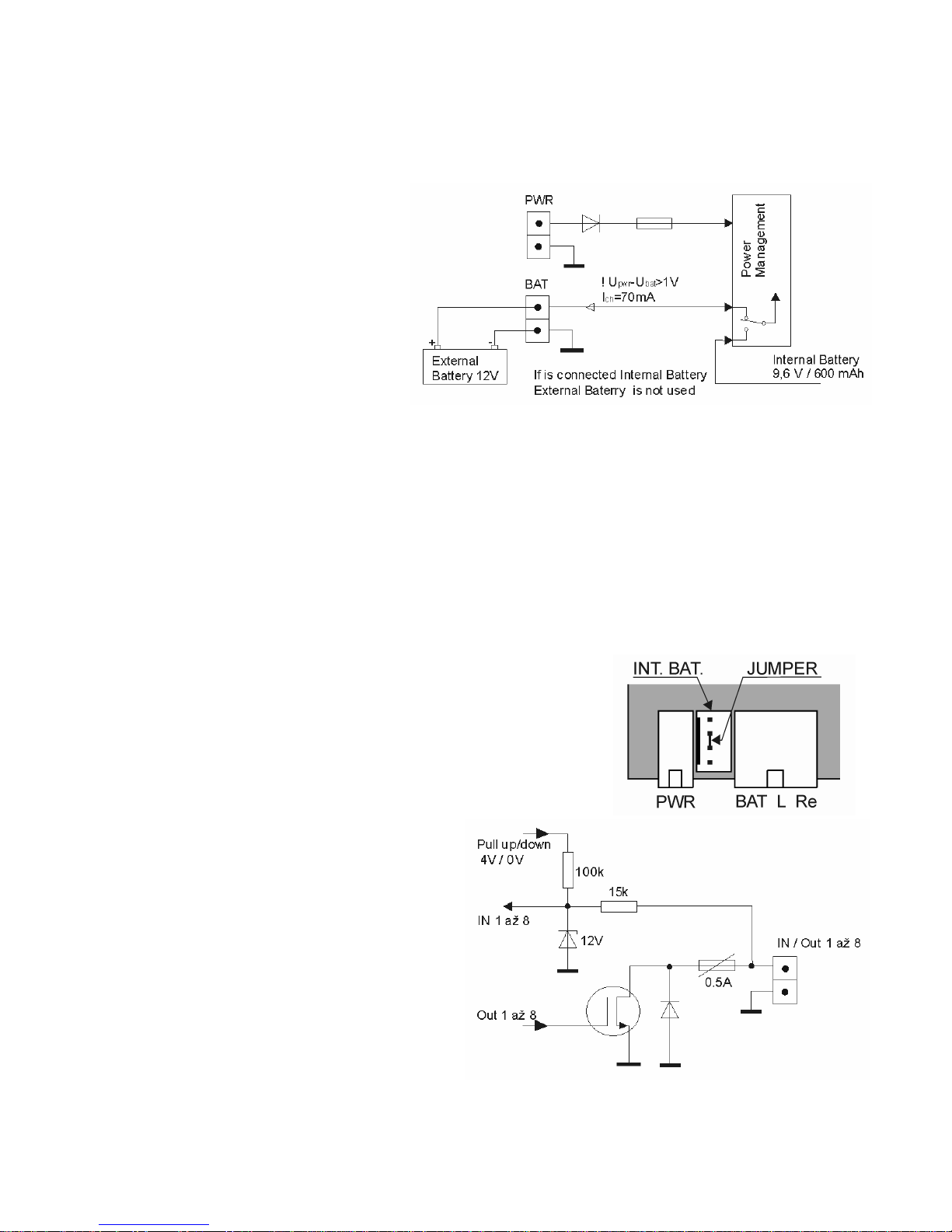
2.2.1.Power Sources................................................................................................................8
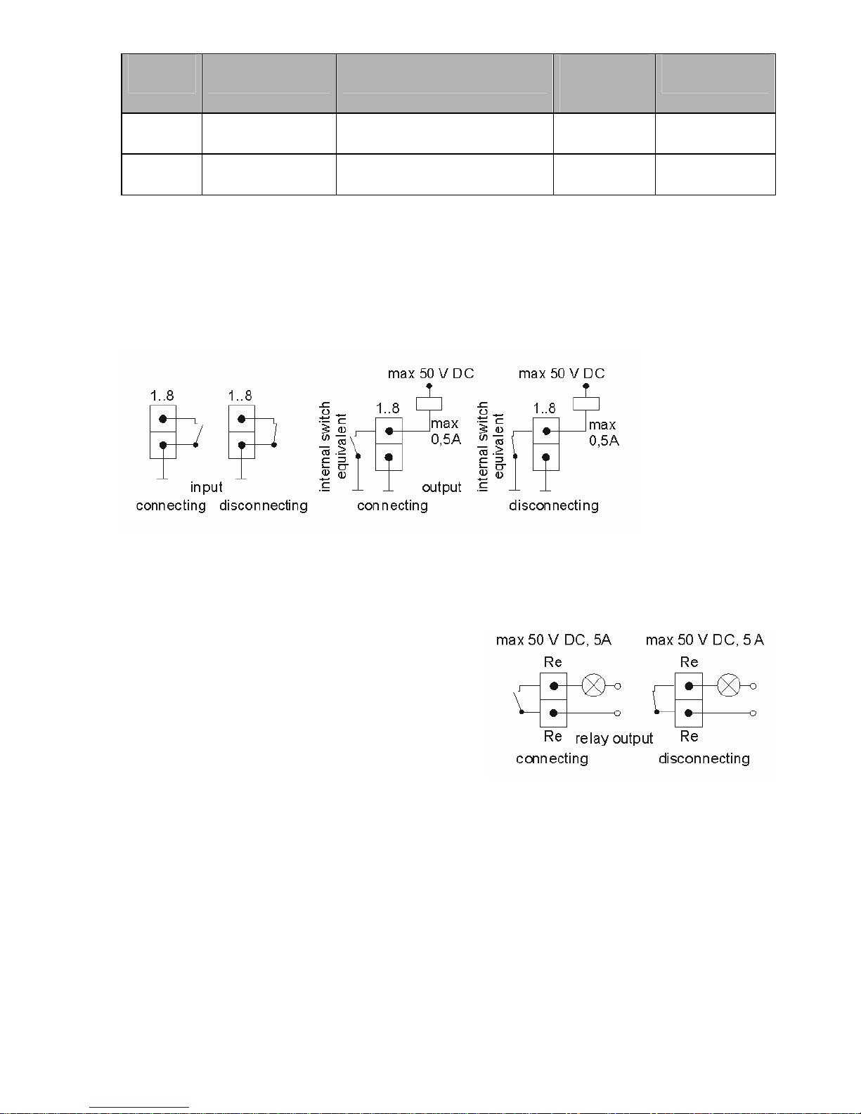
2.2.2.BinaryInputs/Outputs.....................................................................................................8
2.2.3.RelayOutput...................................................................................................................9
2.2.4.LEDOutput.....................................................................................................................9
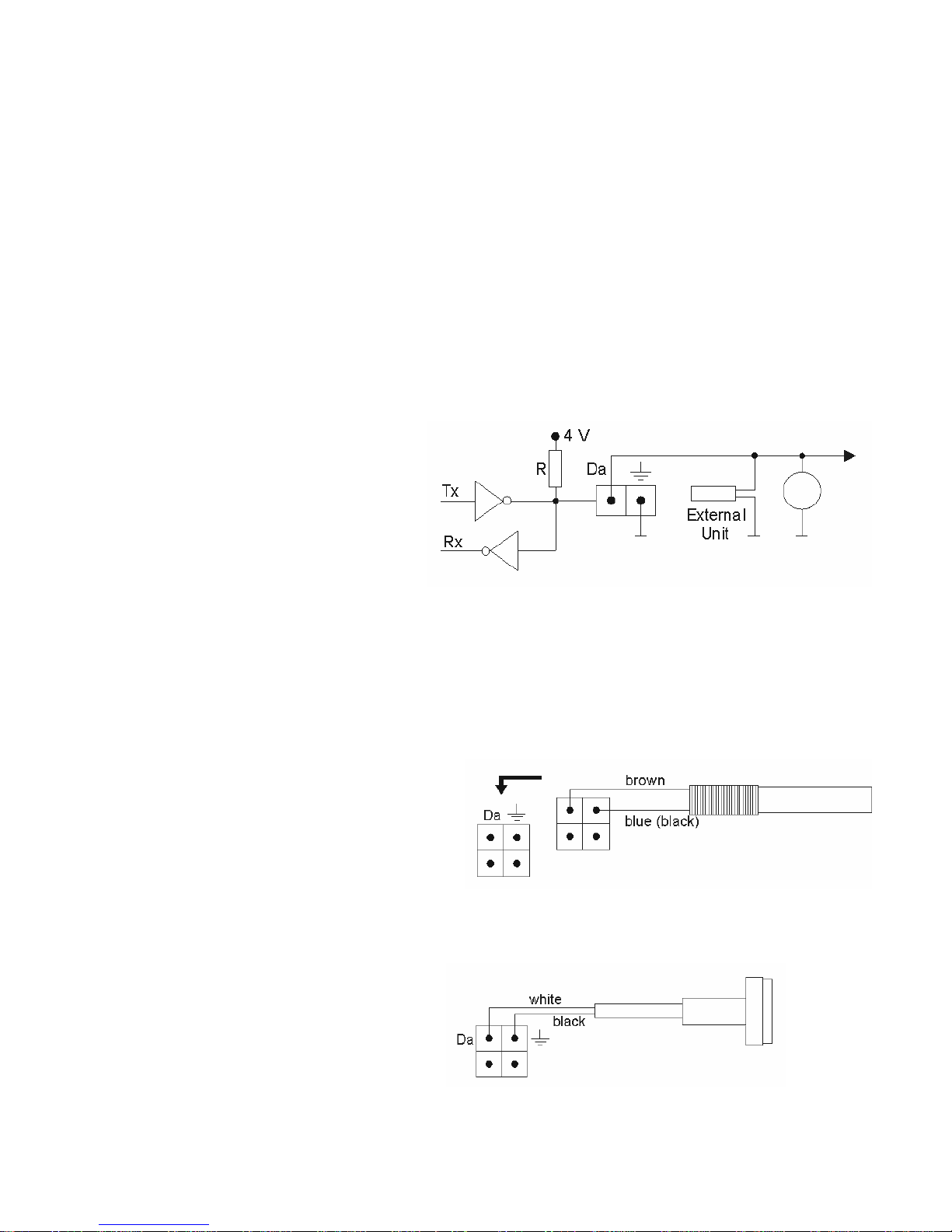
2.2.5.DALLASBus.................................................................................................................10
2.2.5.1. Digital ThermometerED 060100........................................................................10
2.2.5.2. ID KeyReader ED 060500.................................................................................10
2.2.5.3. ID Keys.................................................................................................................11
2.2.5.4. External unitof analogueinputs..........................................................................11
2.2.6 RS232 Serial Connection.............................................................................................11
2.2.7.GPS Antenna ED 002 002............................................................................................12
2.2.7.1. GPS Point.............................................................................................................12
2.2.7.2. GPS Trace............................................................................................................12
2.2.7.3................................................................................................................................12
2.2.8.GSMAntenna ED 001001, ED 001 002 .....................................................................12
2.2.9.SIMCard.......................................................................................................................13
2.2.10. Microphone Connection ED 060 250.........................................................................13
2.2.11. Loudspeaker Output...................................................................................................13
2.2.12. Indication.....................................................................................................................13
3. Setting into Operation andControl................................................................................................14
3.1. Setting into Operation............................................................................................................14
3.2. Initialization and Reset..........................................................................................................14
3.3. Control....................................................................................................................................15
3.3.1.Control fromPC Usingthe RS232 Interface...............................................................15
3.3.2 Control via GSM.............................................................................................................15
3.3.3.Control via GPRS..........................................................................................................15
3.4. Control and Configuration Using the SMSmessages..........................................................16
4. SWSupplied withGB 060.............................................................................................................20
4.1. The GB 060 ControlPanel Program.....................................................................................20
4.2. GPS RemoteConnector........................................................................................................20
4.3. Remote Connector................................................................................................................20
5. Basictechnicalparameters:...........................................................................................................20
6. Warrantyconditions.......................................................................................................................21
WARRANTYCERTIFICATE.............................................................................................22

5
1. Modelrange, safety, accessories
1.1. GB 060Models
Model name 8× I/O
inputs/outputs Internal
battery Dallas
bus GPS GPRS
GB060 300
GB060 301
GB060 310
GB060 311
GB060 314
GB060 315
GB060 514
GB060 515
Theletterfollowing themodelname(i.e.A,B,C...)thendeterminesaccessory range
deliveredintheset.
1.2. SafetyInstructions
Power Supply. ConnecttheGB060toapermittedpowersourcesonly.Suchapower
sourceistheSA 012 503 AC/DC adapterincludedinthesetor alternativelythe12V
powersourcefromavehicle.
OperationalEnvironment. GB060 isintendedfor operationindry environment
withoutany aggressivegasesor fluids.Donotexposetheproductstowateror
humidity,keepthedeviceoffextremetemperatures,do notinstallthedevicecloseto
radiators,openfireor on directsunshine.Do notexposethedevicetoextremelow
temperatures,e.g.inacar parkedoutsideinwinter.Protectfromwaterandother
liquidsgetting intothedevice. If thishappens,thereisafirerisk and theelectricshock
hazard.Insuchacasedisconnectthedevicefromthemains.
Maintenance. Itisnotnecessary toopenor dismantlethedeviceif operatedinthe
usualway.Beforedismantlingthedevicefor any reasons(e.g.inserting abackup
battery)disconnectitfromallpowersources.During assembly,installation and
operation ofthedeviceseetoitthattheinsulation oftheoftheconnecting cablesis
intact.
High-FrequencyEnergyEffects. GB060 shouldnotbeinstalledor operatedinany
rooms orspaceswhereoperationof cellular phonesisprohibited. Beforeinstallation in
acar,check whethercellularphoneoperation (and,consequently,theGB060) is
permittedinyour typeof car.Installing theGB060 inplaceswithan increasedlevel of
electromagneticradiation isnotadvisableas thereliabilityofthedevisecan be
decreased.

6
1.3. Configurationof the GB 060
Code Descriptionofcomponents
GB 060 x00A
GB 060 x01A
GB 060 x10A
GB 060 x11A
GB 060 x14A
GB 060 x15A
GB 060 xxx TheGB 060 model
ED 001 001 GSMantenna(3dB) ○○
ED 001 002 GSMantenna – flat, for sticking on glassor plastic ○○○○
ED 002 002 GPS antennaactive – with SMB connector ────
SA 012 603 AC/DC Adapter 220 V/12 V DC, 600 mA, cable1,5 m,
connectorMolex2pin ○○
CB 160 021 2-meter-long serial cablewith theRJ45 connectors& the
RJ45 /Canon 9 pinsreduction piece
CB 161 000 Electro-assemblyset: 8 pcsself-cutting grip, 2 pcscable
connector, 3 pcsbinding tape,earth-wireloop ○○○○
CB 161 002 2-pin connector, 2 pcs. Of2-meter-long stranded wire
with atubeintotheconnector ○○○○
CB 161 004 4-pin connector, 4 pcs. Of2-meter-long stranded wire
with atubeintotheconnector ──
CB 161 006 6-pin connector, 6 pcs.of2-meter-long stranded wire
with atubeintotheconnector
CB 161 011 10-pin connector, 10 pcs.of2-meter-long stranded wire
with atubeintotheconnector
CB 161 033 10-pin, 6-pin, 4- pin connectors, 1 pieceeach, pins
included ○○○○○○
ED 060 100 Temperature sensor (-25°C to+90°C), Accuracy: 0.5°C,
2-meter-long cable ──○○
ED 060 200 External unit ofanalogueinputs ○○○○○○
ED 060 250 Microphonewith a1.5-meter-long cablewith aconnector
(Jack3,5 mm) ○○○○
ED 060 260 Loudspeaker with amplifier for audiooutput with MUTE
mode ○○○○○○
ED 060 500 Identifying keyreader with a30 cmlong cable ──○○
ED 060 550 Identifying keywith an uniquecode, in aholder ──○○
ED 060 600 LED for assemblyonapanel, 1,5-meter-long cable ○○○○
ED 060 601 Push-buttonfor assemblyon apanel, 1,5 mcable ○○○○
ED 060 002 Internal back-up battery9,6 V/600 mAh – 24 hrs. back-up
□+ □+ □+
ED 050 400 Motion detector with keyboard ○○○○○○
ED 050 300 Doublerelayoutput for electricalappliancesswitching ○○○○○○
ED 060 602 12 V Sound signalization ○○○○○○
ED 060 603 Sound signalization with discontinuoustone+ LED / 12 V
○○○○○○
InstallationCD with GB 060 Control Panel software
GB 060 Directionsfor Use
Note: ( ) numberofaccessorypiecesincluded in theset
(○)accessorycan beused with thegiven typeofproduct
(─)accessorycannot beused with thegiven typeofproduct
(□)accessorycan beused onlywhenassembled bymanufacturer
(+) accessoryinstalled insidethedevicealreadyfromproduction

7
2. GB 060Instalation,Functional Description
2.1. GB 060 - connectors

8
2.2. Functional Description
2.2.1.PowerSources
NominalVoltage12 V DC (Max. 25V),Current Max.0,5A
PowertotheGB 060unit can
befedusing eitherthe
standard AC/DC adapter
SA 012 503 or the12 Vpower
sourcefromvehicle.Power
sourcemustbeconnectedto
the2-pinpowerconnector
PWR+12 V.Incaseofpower
outageitispossibletouse
externalbattery connectedto
theBAT+12Vclip.
Onlya12Vnominal voltagebatterycanbeconnectedto the device!
Themodelswithinternalback up battery 9.6 V / 600 mAh(labeledED 060 002)
included.Inthesecasestheexternal batteryhasnouse.
Thecharging currentofinternalorexternalbattery is70 mAwhilethepowersource
voltageof GB 060 hastobeat least1Vhigherthanthebattery voltage.
TheGB 060 deviceprovidesoptimalrechargingoftheinternalor externalbattery.
However,thecharging voltageof GB 060 mustbeat least1Vhigherthan thebattery
voltage.
NOTE:Ifyou removeinternalbattery fromGB 060 and
wanttouseexternalback up battery,itisnecessary to
connectinterconnecting jumperintheinternalback up
battery connectorso thetwopins inthemiddleare
connected.
2.2.2.BinaryInputs/Outputs
Thedeviceisprovidedwitheight
independently-programmable
inputs/outputs.Thesignalscanreach
twolevelsonly:L(low)orH(high).
Theinput signalscanbeinformation
on thequantitiescontrolled(e.g.
temperature).By theoutputsignals
thequantitiescan becontrolled.The
inputs/outputsareledouttoa10-pin
connector markedwithnumbers and
a+4Vclipand“ground”symbol.

9
I/O pin Low(L) High (H) Load
Carrying
Capacity
Input
Resistance
Input
Max. 0,5V Min.3V,Max. 30V – Approx.15
kΩ
Output
Max. 0,3V OpenCollector,Max50V
Bias3,3V/115kΩ0.5A –
•Anotconnectedinputisonhigh level (H).
•Outputisprotectedfromovercurrentbyelectronicretracting safety-fuse.
•The+4V clipisintendedfor powersupplyofapossiblefront-end logic.Maximum
loadis150mA.
Functions and recommendedconnection ofexternalinputandoutputcircuits:
Binaryinput/outputcircuitshavetobeconfiguredforeach requiredfunction using the
GB 060 Control Panelsoftware.
2.2.3. RelayOutput
Therelay outputisagalvanicallyseparated
outputfordirectcontrolofpowerappliances.
Theoutputisledouttoa6-pinconnector
markedwithtwoRe symbols.
Therelay outputmustbeconfiguredbythe
GB 060 ControlPanelsoftwareforthe
requestedaction,andthenitispossibleto:
2.2.4.LED Output
An outputfor aLED thatcan belocatedout ofGB060. Theoutput isledout toa6-pin
connector markedwiththeL+andLsymbols.
The LEDindicatesthesestates ofGB060:
•the LEDisoff group1isinactive(unlocked)
•blinkseach 0.1secforaperiodof1sec group1isactive(locked – basicstate)
•blinkstwiceper0.1sforaperiodof 3sec group1isactive, butthereisnoGSM
signal

10
•blinksquickly actionin progress – waiting for finishing
action
•LEDonfor1sec actionfinished
•blinkstwiceper1sec keysigningoffaction inprogress
•LEDpermanentlyon a phonecalloradatacallinprogress
2.2.5.DALLASBus
TheDALLAS Bus isprovidedwith onemasterunitand oneor moreslaveunits.The
equivalentconnectionoftheslaveunit isshowninthediagram,theactualmasterunit
consistsofaprocessor.Each oftheslaveunitshas tohave anopen-collectoror a
three-stateoutput. Thecommon collectorresistor(pull-up)isconnectedon themaster
unitside.TheDALLAS bus has justonewiretowhich allthe externalslaveunitsare
connected. Thelengthofthewirecan normallybeapprox. 100m. If atelephonecable
withthewirestwistedintopairsisused(capacityapprox.30 pF/m),thedistance
betweenthematerunit andtheslaveunitcanbeupto300meters.
TheIDkeys havea16-digit
hexadecimalnumbermarkedon
thefrontside.Thethermometers
havethenumberon an IDtag.
Theexternalunitscan beadded
toGB 060 using theconfiguration
toolsinGB 060 ControlPanel
softwaredeliveredwiththe
device.
2.2.5.1.DigitalThermometerED060100
Upto10thermometers can beconnectedtoaGB 060unit at atime.
Temperaturedataretrieved fromthe
sensor istreatedby theautomatonas
an analogueinput.Anupperlimitand
alowerlimitcan besetup for each
analogueinput.An increaseofthe
analoguevaluetotheupperlimit or
lowerlimitwillbeinterpretedby the
automaton as an event.
2.2.5.2.IDKeyReaderED060 500
TheconnectiontotheGB060 is
showninthefollowingdiagram:

11
2.2.5.3.IDKeys ED060550
Each individualidentificationkeyisconsideredan external unitthathas tobeaddedto
thesystemusing theGB060 ControlPanel. TheGB 060 systemcan havean
unlimitednumberofID keys added.
AfterputtingthekeytotheED 060 500 reader,thekeyIDnumberisenteredintothe
GB 060 controlunit.
Onlyonekeycan beloggedinthe
systematatime.Loginandlog offof
an IDkeywillbeinterpretedby the
automaton as an event. Partofan
invokedaction (byanyevent)can
alsobeakeylogoff.
2.2.5.4.External unitofanalogueinputs ED 060 200
Externalunitofanalogueinputs ED 060 200 contains forinputs – 2currentloops
4-20 mAand 2voltageloops 0-10 Vthatenabletoconnectdifferentkinds of
sensors, for examplebarometers, humiditymeters, water-level indicator etc. Maximum
numberofconnectedanalogueinputsandthermometers is10 while1external unit=
4analogueinputs).
2.2.6RS 232Serial Connection
RS 232isastandard serialchannelforcommunicationwithamasterPC.
RS232enables:
- downloadinganduploadingoftheconfiguration
- readingstatusofmeasuredvaluesand identificationdata,entering outputvalues
- readingdatarecordedinmemory – Report
- connectingremotedeviceswithRS 232 interfacetoaPCusing theGSM
connection
- connectingahandhelddevice/PDAfornavigation(GB060worksasGPSreceiver)
- connectingaprintertoprintincomingSMSmessages
Description ofsignalsontheGB 060 side:
Pin Name RS232 V.24 Direction
1 (CD) CF 109
2 TxD BA 103 =>
3 RxD BB 104 <=
4 (DTR) CD 108.2
5 GND AB 102 ==
6 (DSR) CC 107
7 CTS CB 106 <=
8 RTS CA 105 =>

12
Used: 2,3,5,7,8,Connected:1,4,6
2.2.7. GPS AntennaED002 002
GPS antenna ED 002 002 thatcomeswitha3meter-long cablegetsconnectedinto
theSMBcoaxialGPS connector.Itslocation mustbeinhorizontalposition withdirect
viewofthesky.GSMsignalpassesthroughplasticmaterialsandglass butnot
through metalsand mirror glass.ThestrengthofGPS signalisdeterioratedby
weatherconditions such asheavy snowing,iceand frostor snowovertheGPS
antenna,theGPS signal alsogetsdefusedbyhigh buildingsor trees.
GPS - Global PositioningSystem
GPS enablesusertodetermineaposition inany placeon theplanet. Itisbasedon
transmissionofsignalfromsatellitesthatcircleintheheightof20 200 km.Thebasic
condition toread thegeographicalcoordinatesissimultaneous receptionofsignals
fromatleastfour satellites.Theaccuracyoflocationisabout15 metres.Thesystem
doesnotworkintunnelsand buildings.
2.2.7.1.GPSPoint
PartoftheGB 060 configuration canbeentering thegeographiccoordinates
(longitudeand latitude)asacenterand distanceinmeters asthecirclediameter.The
innerspaceofsuch circleisdefinedas aGPS point.LeavingaGPS pointorentering
aGPS point willbeinterpretedas anevent.
2.2.7.2.GPSTrace
PartoftheGB 060 configuration canbeentering distancethatwill bedefinedas a
GPS trace. TheGB 060 continuouslygathers thegeographiccoordinatesand
calculatestheactualdistancemoved.Moving particulardistanceinthelengthofGPS
tracewillfulfilloneofthetwoconditions foran action.To preventtheaction frombeing
carriedouttoo oftenduring high speedtravel, thesecond condition can besetas
elapseofadefinedtimeperiod.TohavetheGB 060 launchan action,thedistance
movedhas tobecompletetraveling oftheGPS tracedistanceor elapsingthe
minimumtimeperiod.
2.2.7.3.SpeedAction
It ispossibletodefineaspeedlimit GB 060configuration.Exceeding such limitwill
lead toadefinedaction.
2.2.8. GSMAntennaED001 001,ED001 002
Magnetic GSM antenna ED 001 001 comeswitha3meter-long cableand connects
intotheGSMconnector intheuppersideof theGB060 case. Antenna ED001002 is
equippedwithself-adhesivetapeand isdesignedtobe mountedtoglass orplastic
material,avoidmetalsurfacesastheywouldsuppress theGSMsignalreception.
GSMModule

13
GB 060 includesGSMmodulewhich enablestwo-wayconnection inthe900/1800
MHz band intoaselectedGSMnetwork afterthelog-inprocedureofaSIMcard
inserted.
Itisusedmainlyfor:
•transmitting alertorinformational messagesandcallsfromtheGB 060 unit
•transmitting controlcommandstotheGB 060unit intheformofSMSmessages
•incoming ringing(free of charge)for remoteswitchingof connected appliancesusing
amobilephone
•incomingcallforvoicetransmission using thevoicechannel
•dataconnection forreadingandchangingtheconfiguration, readingstatusand
readingreportfileremotely
•sendingdatapacketswithcurrentpositionanddevicestatusesusingGPRS
2.2.9.SIMCard
SIMcard isinsertedintoslotnexttotheGSMantenna connector.To releasetheslot
press theyellowbutton next toit. Find asuitabletool forpushing thebutton, do not try
toopentheslot usingforce. Wheninserting,puttheSIM cardintheplasticplateinthe
slot and pushitinside.
2.2.10. MicrophoneConnection ED060250
Themicrophonecan beconnectedusingthecoaxialconnectors(Jack3,5mm).The
connectingcablescan notbelongerthan 3meters.Connection ofadifferent
microphonemustbeconsultedwiththeGB 060manufacturer.
2.2.11.LoudspeakerOutput
For loudcommunication withtheremotedevice,itispossibletopurchaseanoptional
accessory – highpoweramplifierED 060 260.Thisamplifierhas powervoltage12 V
and poweroutput10Wwithloudspeakerloadofimpedance8 Ω.
2.2.12. Indication
ThefrontpanelisprovidedwithfourLEDstoindicateoperationalstates. Thelistofall
theoperationalstatesthatcan beindicated(signaled) isgiveninthefollowing table:
WhentheLEDisblinking,thetimegivenbeforetheslashisthelight-up,thetime
givenaftertheslashisthelight-outtime.
POWER
•OFF Nopowersourceconnected
•PermanentlyON External powersourcesupply(PWR, paragraph2.2.1.)
•Blinking 1,2s/0,2s Externalpowersourcesupply, recharging thestandby
battery
•Blinking 0,2s/1,2s Standbybatterypowersupply
•Blinking 0,2s/0,2s Standbybatterypowersupply, battery flat
GSM
•OFF GSM moduledoesnotworkorisnotloggedinthenetwork

14
•Blinking 0,6s/0,6s GSM moduleisjustloggingin
•Blinking 0,7s/3s GSM moduleisloggedand workscorrectly
•PermanentlyON indicationdataconnectionorcall inprogress
GSMACT
•OFF GSM moduleatrest(nocommunicationtakesplace)
•Blinking 1s/3s Incoming callringingindication
•Blinking 0,7s/0,7s Call-connecting-in-progress indication
•PermanentlyON Call-connectedindication
•Blinkoncefor1s IndicationSMSsending/receiving
IN /OUT (red)
•OFF Noprogrammableactiontakesplace
•PermanentlyON An action inprogress
3. Setting intoOperationand Control
3.1. SettingintoOperation
• Check thattheSMScentersettingsontheSIMcardarecorrect. InsertSIMcard in
GB060. IftheSIMcardisblockedbyPIN,switchit offinamobilephonefirst.
• ConnectGSMantenna
• ConnectGB 060 toserialport ofPC
• Connect powersourceforGB 060
• Install softwareGB060ControlPanelfrom CD
• Run theGB 060Control Panel andcreateaconfiguration – helpforusing theGB
060 ControlPanelcanbefoundusingtheF1 key.
• Send theconfiguration intoGB 060
TheGB060 unit canbeswitchedoff bydisconnecting theexternal powersource.
Modelswithinternal battery require pushing theINITbuttonfor ashorttimeafter
disconnecting theexternal powersourcetoprevent discharging ofthebattery.
3.2. InitializationandReset
RESET iscarriedoutby pressingtheINITbutton.Resetisindicatedby allfourfront
panel LEDs onforaperiodof0.5 secfollowedbyall LEDslighting uponeafterone.
INIT iscarriedoutby pressing theINITbutton for 5seconds.INITisindicatedby all
LEDsgoingout.INITwillerasetheuserconfigurationofGB060.
Auserconfiguration can besavedintoGB060 as defaultconfiguration thatisread
afterINIT – fordetailssee theGB060ControlPanelhelp.
Such defaultconfiguration can also beerased – by pressing theINITbutton for
15 seconds. Thiswill beindicatedbytheLEDPOWER lightingup.

15
3.3. Control
Controlof GB 060 – internalconfigurationsettings,switchingoutputs,readinginputs
statusesandinternalvariablesofdevicecanbedoneusingthefollowingoptions:
• UsingtheGB 060Control Panel software
• Viacablein local connection toserialportinPC
• ViaGSMdataconnection
• ViaGPRSdataconnection
• UsingthecommandSMSmessages
• UsingringupofphonenumberofSIMcardinGB060
3.3.1.Control fromPCUsing theRS 232Interface
SerialinterfaceRS 232(RJ 45 connector) enablesusingall featuresofGB 060.For
connectionwithPC, usetheCB 161 020 cable.Installthe GB 060 ControlPanel
softwarethatwillgiveyouverycomprehensivesummaryofthedevice’spossibilities
including contexthelpfor each feature.Youcan createyourownconfiguration using
thesoftwareandsend itintoGB 060.Whenconnectedinon-linemode,you can
check theSTATUSwindowfor statusesofGSM,GPS,GB 060 internalvariables,
inputs, outputs, etc.
3.3.2ControlviaGSM
This connection ismadeovertheGSMdataconnection.Itisrecommendedtousea
GSMmodem.(ItispossibletouseamobilephonewithdatacabletoPCor another
GB060 deviceas aGSM modem). TheSIMcardsusedinconnection must havedata
transmissions enabledfromtheoperator.Incaseofusing an analoguemodemon
fixedtelephonelineconnecting toGB060 theSIMcard musthaveaspecialdatacall
numberactivatedfromoperator.
Usingthisconnection,itispossibletodooperationswithconfiguration, statusesand
reportinGB 060 Control Panel insimilarway as inlocalconnection.
3.3.3.ControlviaGPRS
UsetheGPRSinternetaccess vianetworkaccess point(APN)fromyouroperator.
TheSIMcardin GB060 musthaveGPRStransmissionsenabled.
GPRS DataConnectionUsing theUDPProtocol
PCthat will beinitiating theconnection must havepublicIPaddress. Action inGB060
will launch acall toselectednumberfromphonedirectory that representstherequired
GPRSconnection.GB060 willconnectto theinternetand maketherequired
connection.Thisconnection willbeset tothepublicIPaddress ofthePCand selected
UDPport. GB060 Control Panel must beswitchedtomode“Wait forconnection”.

16
GPRSDataConnectionUsing theTCPProtocol
To usethisconnection,theaccess torelevantproxyservermustbeprovided.Action
inGB060 willlaunchacalltoselectednumberfromphonedirectory thatrepresents
therequiredGPRSconnection.GB060 will connecttothe internetand makethe
requiredconnection.Thisconnection willbesettothepublicIPaddress oftheproxy
serverand selectedUDPport. GB060 ControlPanelwilll thenconnectwiththeproxy
serveron selectedTCPportusing theTCPprotocoland log inusing thedefineduser
nameand password.Theproxyserverwillprovideconnection betweentheControl
Panel andtheremoteGB060.
3.4. Control andConfigurationUsingthe SMS messages
It ispossibletoconfigure,controlandremotelyread valuesfromGB 060 using SMS
messages.
Structure of Command SMS
CommandSMSstructure
Command SMSalwaysbeginswithcurrentPINof GB060, followedbyspaceand key
word ortheinquiry or command(inTableofSMScommands thekeywords are
markedby capitalletters).Beforekeyword there can be nameofobjector nameof
command - separatedbydots.Keywordisfollowedby command valueor question
markforan inquiry.OneSMScan containmorecommandsor queries,theymustbe
separatedby aspace.Thenumberofcommandsor queriesinonecommand
messageisonlylimitedbythelengthof SMS - 160characters.
ExampleofcommandSMS: 1234POWERGPSTACHO155
1234 - access PINofGB060
POWER – powersupplystatusquery
GPS – position query
TACHO155 – settingthespeedindicator tovalue155

17
BasicCommandSMS
PIN - GB060accessPIN
pinPIN x x=? - query,x=newPIN – changePIN
SW, HWversion, GB060serialnumber
pinPRODUCT
Communication adapterSW, HWversion, serialnumber(ifinstalled)
pinADAPTER
Power supplystatus,internalbattery, charging
pinPOWER
GB060 reset
pinRESET
GB060 initialization
pinINIT
GB060 RS232settings
pinCOM xy x=? - query,
x=baud rate(1200,2400, 4800,9600,19200)
y= dataflow control, y=1 - enabled, y=0–disabled
GB060 timesettings
pinRTCx x=? - query,x=dd-mm-rr hh:mm:ss
IDkeyquery
pinKEY
Change ofnumberinphonedirectory
pinname_of_phone_no.x x=? - query,x=newphonenumberininternational
format
SMScommandsforGSM
GSMoperatorquery,creditvalue,BTS cellID, GSMsignal value
pinGSM (signal valueisinrange0-32,0=min.)
Creditquery
pinCREDIT
Settingsofcreditquery
pinCREDITMODEx x=? - query,x=0 - donotread, x=1 - read from
SIM,
x=2 - read using USSDcode
USSDcode forcredit querysettings
pinCREDITCMD x x=? - query,x=USSDcode,(i.e.inCZ:T-mobile:
*101#,Oskar:*22#, Eurotel:*104*#)
Creditvaluelow limit
pinCREDITLOWx x=? - query,x=creditvalue

18
SMScommandsforGPS
Abbreviations: jgpsb=GPS pointname,jgpst=GPStracename
Positionquery
pinGPS Exampleof reply: GPS 5025.220300N16
10.078100 E=50° 25,2203' north16° 10,0781'
east
Positionquery - decimalreply
pinGPSD Exampleof reply: GPSD50.420261N16.167929 E
=50,420261°north16,167929°east
Positionquery - replyusingGGANMEAsentence
pinGGA
Positionquery - replyusingRMCNMEAsentence
pinRMC
GPS speedindicatorquery
pinTACHOx withoutx - query, x=value - newvalueof speed
indicator
Speed query
pinSPEED
GPS pointdiametersettings
pinjgpsb.LENx x=? - query,x=valuein[m]
GPS trace distancesettings
pinjgpst.LEN x x=? - query,x=valuein[m]
GPS trace timeperiodlimitsettings
pinjgpst.INTERVALx x=? - query,x=valuein[min]
SMScommandsforbinaryinputs/outputs
Queryonlistand statusesofbinaryinputs
pinINS
Queryonlistand statusesofbinaryoutputs
pinOUTS
Outputsettings
pinoutput_namex x=? - query,x=0 - set outputvalue tolog.0
x=1 - setoutput valuetolog.1
Relayoutputsettings - operation mode
pinoutput_name.MODEx x=? - query,x=0 - disabled, x=1 activeinlog.0,
x=2 activeinlog. 1
Relayoutputsettings - pulselength
pinoutput_name.DELAYx x=? - query,x=0 - nopulse, x=value1-255[s]
Counterqueryand settings
pinoutput_name.COUNTER x x=? - query,x=value - newcountervaluesettings

19
SMScommandforactions
Launchinganaction
pinaction_name Reply: action_name.run
Enabling action
pinaction_name.ENABLEx x=? - query,x=0 - disabled, x=1 - enabled
Adding an action into group
pinaction_name.GROUPx x=? - query,x=0 - group 1... x=7 - group 8
SMScommandsforanalogueinputs
Queryonlistand statusesofallanalogueinputs
pinAINS
Queryonstatusofanalogue input
pinan.input_name
Delaybeforeactionsettings
pinan.input_name.DELAY x x=? - query,x=valuein[s]
Lowlimitsettings
pinan.input_name.LOWx x=? - query,x=newlowlimit value
High limit settings
pinan.input_name.HIGH x x=? - query,x=newhighlimit value
SMScommandsforcalling
Audioinputsettings
pinAUDIOIN x x=? - query,x=value0-100, 0=min.100=max.
Audiooutputsettings
pinAUDIOOUTx x=? - query,x=value0-100, 0=min.100=max.
Callbackwithlistening-in
pinCALLBACK (callsback totheSMSsender)
Voicecall todefinednumberwithlistening-in
pinCALLVx x=calledphonenumber
Data calltodefinednumberwithconnectionto RS232
pinCALLMx x=calledphonenumber
Data calltodefinednumberwithconnectionintoconfiguration
pinCALLRx x=calledphonenumber
SMScommandsfortimersandactionplanners
Abbreviations:nt=nameoftimer,nap= nameofactionplanner
Timeperiodsettings
pinnt.PERIOD x x=? - query,x=timevaluein[s/10]
Enableactionplanner
pinnap.ENABLEx x=? - query,x=0 - disable, x=1 - enable

20
4. SWSuppliedwith GB060
4.1. The GB 060 Control Panel Program
PartoftheGB060 softwareinstallation istheGB060 ControlPanelsoftware,which
servesas aprimary toolfor thedeviceconfiguration and fordetection ofthedevice's
operationalstateincludingthestateofallitsinputs.Theprogramconnectstothe
devicethrough eitherdataconnection viathelocalserial interfaceor through theGSM
network using aPC-connectedmodem.Thisprogramincludesan electronichelp
systemwithdetailedexplanation oftheconfiguration procedure.Thisprogramworks
underMSWindows98/2000/Me/XP
4.2. GPS Remote Connector
Installation CD contains GPSRemoteConnectorsoftwarethatprovidestransmission
ofGPScoordinatesfromremoteGB060unitstoPC.GPScoordinatesaretransmitted
using thevirtualserialporttospecialmap software(i.e.Autoroute,Route66,
Mappoint)to display thecurrentposition on themap.The softwareworks under
Windows2000/NT/XPoperationsystems.
4.3. Remote Connector
Part of theinstallationCD isalso RemoteConnector softwarethat enablestocreatea
bridgeconnection overtheRS232 serial interfacefromaremoteGB060unittoyour
PC.DatafromtheremoteGB060canbethentransferredovertheGSMnetworkto
theVirtualCOMportinyourPCandcanbethenusedby anyapplication. Itis
recommendedtouseanotherGB060 unit on thePC sidehoweverotherGSM modem
can alsobeused. BeforeyouruntheRemoteConnector, youhavetoinstallthevirtual
COMportbyinstallingnewhardwareintheWindowsControlPanel; description of
howtodoitislistedintheReadme.txtfile.
5. Basictechnical parameters:
Dimensionswidth×height×depth 144 ×44×88mm
Nominalsupplyvoltage 12 V DC
Powerconsumption instandbymode less than20 mA
Maximalpowerinput 0,5 Aat 12 V
GSM 900 / 1800
Switches1-8 current max. 0,5 A
Relay current max. 5A
REPORTmemorycapacity about3000GPS records**,
extensibleupto12000
Operationtemperaturerangefor GSM module -25 °Cto+65 °C*
Operationtemperaturerangeforotherparts -40 °Cto+85 °C
This manual suits for next models
11
Table of contents
Other Level Cell Phone manuals