manuals.online logo
Brands
  1. Home
  2. •
  3. Brands
  4. •
  5. LEVENGER
  6. •
  7. Indoor Furnishing
  8. •
  9. LEVENGER EURO DESK SYSTEM FD0180 User manual

LEVENGER EURO DESK SYSTEM FD0180 User manual

EURO DESK SYSTEM
Parts list
Unpack and lay the parts on a clean, flat surface. You will need an
additional straight screwdriver. Check that you have all the parts shown in
the diagram below.
The Levenger Euro Desk system is
designed to provide both computer
and traditional desk space. Euro
Desks are sized for use at home or in
the office. They can wrap around you
to the left, right, or on all sides,
conforming to the size and space in
your room.
Either desk can be enhanced with optional accessories such as a drawers,
keyboard tray, trolleys and bookcases.
Levenger Euro Desks are made with solid cherry legs and thick, high-
quality cherry veneer tops.
1
BUILDING YOUR SYSTEM
1 1 pc 2 1 pc
3 1 pc 4 1 pc
A 8 pcs
B 2 pcs
C 2 pcs
D 2 pcs
G
E 15 pcs
F 4 pcs
H
Building the frame
Locate the left leg assembly (3). Insert two wood dowels (A) into the upper
and lower holes in the side of the leg. Insert a cam lock screw (B) into the
middle hole. Be sure that the slot in the screw is parallel to the floor when
fully tightened.
Locate the back apron (2). Insert a cam lock nut (C) into the hole on the
inside of the apron. Be sure that the openings in the
sides of the nut are parallel with the floor. Carefully slip
the leg assembly into the holes on the side of the apron,
so that the cam lock screw slides into the cam lock nut.
Insert a cam lock set screw (D) into the nut and tighten.
Repeat for the right side leg (4).
2
2
4
3
CD
G
A
B
Slot parallel to the floor
1
E
3
4
E
GEE
A
A
A
A
2
Attaching the top
Locate the desk top (1). Insert 4
wood dowels (A) into the holes
at the corners. Set the leg
assembly on top of the dowels.
Insert the 15 long bolts (E) into
the holes on the underside of
the assembly, and fully tighten.
Insert leg levelers (F) into each
leg. Adjust each until the desk
sits at a level position.
3
FF
F
F
F
Installing the drawers
For the Euro drawer, line the
holes in the handle with the
holes in the drawer. Tighten
the three wood screws (A) in
the handle through the inside
of the drawer.
For the large drawer, no
assembly is needed.
To attach the drawer to your
desk, line the holes in the
rails of the drawer with the
holes on the underside of
your desk. Tighten the long
bolts through the bottom of
the drawer rails into the desk
top. For alignment see the
diagrams following.
A3 pcs
B
C6 pcs
A
BA
A
Euro drawer Large drawer
Supersize keyboard tray
1
2
3
4
A 4 pcs
D
C 4 pcs
E 4 pc
B 4 pcs
A
A
A
A
B
B
B
B
DC
C
C
C
D
1
2
4
3
Installing the tray
Insert four mini-lock screws
(B) into the front panel (2).
Slide the screws into the holes
on the front of the tray (1).
Insert mini-lock nuts (A) into
the holes in the tray. Turn
the nuts 1⁄2turn clockwise to
lock them.
Attach the rails to the tray by
tightening the wood screws (C)
through the rails into the
bottom of the tray.
To attach the tray to your desk,
line the holes in the rails of the
tray with the holes on the
underside of your desk.
Tighten the long bolts through
the bottom of the tray rails into
the desk top.
EURO DRAWER AND KEYBOARD TRAY ASSEMBLY
ACCESSORY CONFIGURATION AND PLACEMENT
• Large Euro Desk
• Two Euro drawers
• Large drawer
(This drawing should also be
used to determine placement
of a single Euro drawer or
large drawer by itself.)
• Large Euro Desk
• One Euro drawer
• Supersize keyboard tray
(NOTE: Placement of drawer
and keyboard tray can also
be reversed.)
• Large Euro Desk
• Supersize keyboard tray
(NOTE: When used with a
Large Euro Desk, the
keyboard tray must be
installed offset to either
the left or right—it cannot
be centered.)
• Medium Euro Desk
• Two Euro drawers
(This drawing should
also be used to determine
placement of a single
Euro drawer.)
• Medium Euro Desk
• Large drawer
• Medium Euro Desk
• One Euro drawer
• Large drawer
(NOTE: Placement of
drawer and large drawer
can also be reversed.)
• Medium Euro Desk
• Supersize keyboard tray
Large Euro Desk Medium Euro Desk
EURO ORGANIZER ASSEMBLY
1 2 pcs
2 1 pc
3 1 pc 4 2 pcs
B 14 pcs
C 14 pcs
D 1 pc
A 14 pcs
Parts list
Unpack and lay the parts on a clean, flat surface. Check that you have all
the parts shown in the diagram below.
1
Building the organizer
Insert 6 mini-lock screws (B) and 6 wood dowels (A) into each of the sides
(4). Slide the shelves (1) over the exposed screws and dowels of both sides.
Insert mini-lock nuts (C) into the holes on the underside of the shelves.
Turn the mini-lock nut 1⁄2turn clockwise to tighten.
Insert 2 mini-lock screws and 2 wood dowels into the underside of the
bottom shelf. Slide the middle support over the screws and dowels. Insert
mini-lock nuts into the holes and turn 1⁄2turn clockwise to tighten.
2
2
1
1
3
4 4
C
D
CC
C
B
B
B
B
B
A
A
A
A
A
A
A
C
C
C
D
A
B
EURO CORNER DESK ASSEMBLY
5 1 pc
1 2 pcs
2 1 pc
3 1 pc
4 1 pc D 1 pc
E 5 pcs
B 10 pcs
A 10 pcs
C 10 pcs
Parts list
Unpack and lay the parts on a clean, flat surface. Check that you have all
the parts shown in the diagram below.
1
Building the desk
Set the table top (5) upside down. Attach the outer legs (1) by sliding a long
bolt (C) through a locking washer (B) and then a regular washer (A). Insert
the bolt through the inside of the table top into the leg and tighten. Repeat
for each of the legs.
Insert leg levelers (E) into each leg. Adjust each until the desk sits
at a level position.
2
11
2
34
5
A
B
C
E
E
EE
E
EURO QUARTER-ROUND ASSEMBLY
1
2 3 pcs
A 6 pcs
B 6 pcs
D 3 pcs
C 6 pcs
Parts list
Unpack and lay the parts on a clean, flat surface. Check that you have all
the parts shown in the diagram below.
1
Building the desk
Set the table top (1) upside down. Attach the legs (2) by
sliding a long bolt (C) through a locking washer (B) and
then a regular washer (A). Insert the bolt through the
inside of the table top into the leg and
tighten. Repeat for each of the legs.
Insert leg levelers (D) into each leg.
Adjust each until the desk sits
at a level position.
2
A
B
C
D
D
D
2
2
2
1
EURO STORAGE TROLLEY ASSEMBLY
2 2 pcs
3 pcs
(3 Drawer Storage)
1 1 pc
G 6 pcs
9 pcs (3 Drawer Storage Trolley)
F 1 pcs
E 1 pcs
H 4 pcs
2 pcs (3 Drawer Storage Trolley)
I 4 pcs
C 2 pcs
D 5 pcs
B 2 pcs
A 16 pcs
Parts list
Unpack and lay the parts on a clean, flat surface. Check that you have all
the parts shown in the diagram below.
1
Building the trolley
Set the trolley on its top. Line up each caster
(B and C) with the predrilled holes, and
attach them using the longer screws (A).
To attach the front wheel, open the bottom
drawer, while the trolley is upside down.
Line up the wheel (E) with the predrilled
holes and attach using the small screws (D).
To attach the handles, set the trolley on its
wheels and open one drawer at a
time. Line up each handle with the
holes in the drawers. Attach using
the countersunk screws (G).
Set the folder rails (H and I) into the
drawers. Letter folders are inserted
front to back, while legal are inserted
side to side.
2
B
C
B
CA
F
1
F
D
DD
E
H
H
I
I
I
H
I
H
F
G
FG
1
2
2
GG
G
G
EURO PRINTER/FAX TROLLEY ASSEMBLY
A 24 pcs
B 16 pcs
E 1 pc
F 4 pcs
C 16 pcs
D 16 pcs
G 4 pcs
H 2 pcs
I 2 pcs
Parts list
Unpack and lay the parts on a clean, flat surface. Check that you have all
the parts shown in the diagram below.
1
Building the trolley
Insert 4 mini-lock screws (B) and 8
wood dowels (A) into each of the
sides (1). Slide the middle
supports (2) over the
exposed screws and dowels
at the top of the trolley.
Insert mini-lock nuts (C)
into the holes on the inside
of the supports. Turn the
mini-lock nut 1⁄2turn
clockwise to tighten.
Slide the middle shelf (3)
and bottom support (4) over
the exposed screws and
dowels at the bottom of the trolley.
Insert mini-lock nuts (C) into the holes
on the underside of the shelf and the
back of the support. Turn the mini-lock
nut 1⁄2turn clockwise to tighten.
2
1
1
2
2
3
4
A
A
B
A
A
B
A
B
A
A
A
B
A
A
B
A
A
A
B
AA
A
B
C
C
C
C
C
C
3 1 pc
5 1 pc
2 2 pcs
4 1 pc
6 1 pc 8 1 pc
9 1 pc
71 pc
1 2 pcs
RightLeft
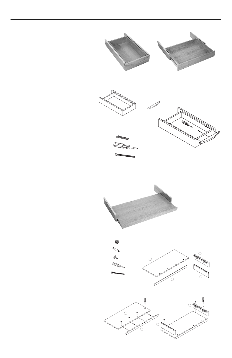
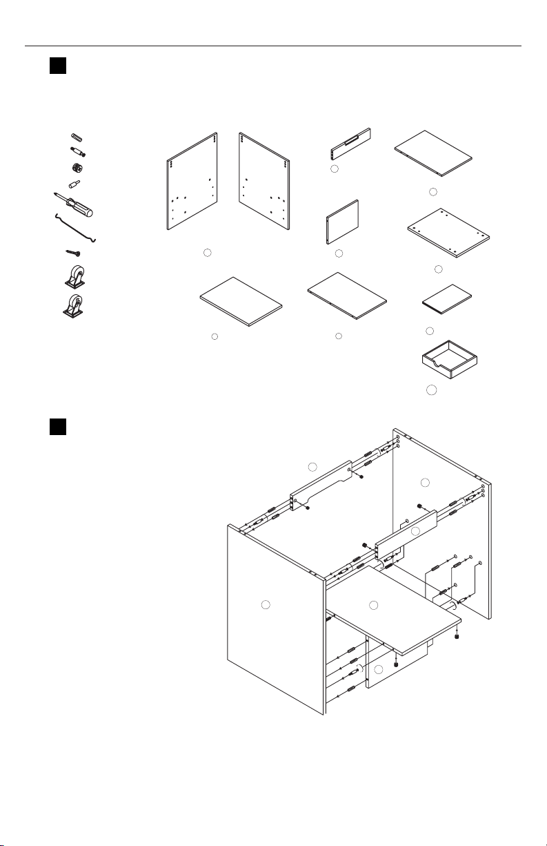
Attaching the top and bottom
Insert 4 mini-lock screws (B) and 4
wood dowels (D) into the top (6) and
bottom (5). Drop the assembly on top
of the bottom and set the top on top
of the assembly. Insert mini-lock
nuts (C) into the holes on the inside
of the sides. Turn the mini-lock nut
1⁄2turn clockwise to tighten.
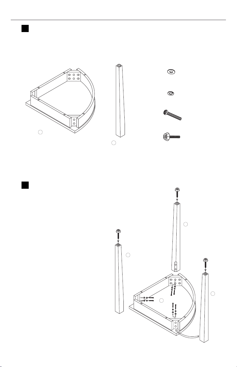
Insert shelf pins (D) into the holes
inside the top portion of the trolley.
Set the shelf (7) on top of the pins so
that the grooves in the shelf sit over
the pins. Insert the wire guides (F)
into the holes in the bottom portion
of the trolley and slide the shelves (8)
over the wires.
3
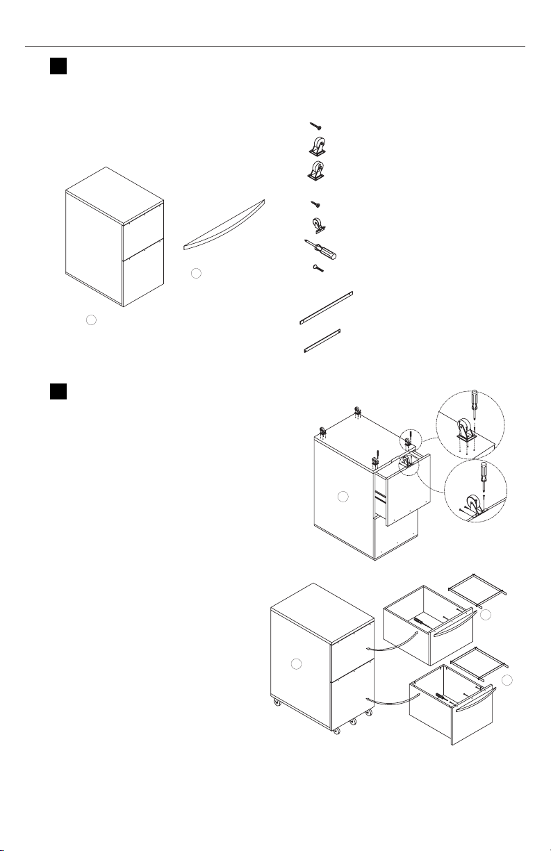
Attaching the casters
You may find it easier to attach the casters without the shelves in place.
Set the trolley on its top. Line the holes in each caster (H and I) with the
holes in the bottom of the trolley. Tighten with the wood screws (G).
Set the trolley on its wheels. Replace the shelves if they were removed. Insert
the wood drawer (9) into one of the shelves on the bottom portion of the trolley
4
H
I
I
H
E
G
H
1
6
5
7
8
8
D
D
D
A
B
ABC
E
D
D
CAB
F
F
A
B
A
B
B
A
C
C
EURO CPU TROLLEY ASSEMBLY
A
B
C
E
F
G
10 pcs
10 pcs
1 pc
16 pcs
2 pcs
2 pcs
D8 pcs
Parts list
Unpack and lay the parts on a clean, flat surface. Check that you have all
the parts shown in the diagram below.
1
Building the trolley
Insert 5 mini-lock screws (A) and 4 wood dowels (D) into each of the sides
(4). Slide the sides (1) into the holes in the sides of both the bottom shelf (2)
and the caster blocks (3). Insert mini-lock nuts (B) into the holes on the
underside of the blocks. Turn the mini-lock nut 1⁄2turn clockwise to tighten.
Line the holes in each caster (F and G) with the holes in the bottom of the
caster blocks. Tighten with the wood screws (E).
2
A
C
B
2
1
B
C
C
A
1
1
3
2
D
123
1
2
3
2 pcs 1 pc 2 pcs
1
1
3
2
C
G
C
E
G
F
F
G
EURO BRIDGE ASSEMBLY
Parts list
Unpack and lay the parts on a clean, flat surface. Check that you have all
the parts shown in the diagram below.
1
Building the bridge
Insert 2 mini-lock screws (B) and
2 wood dowels (A) into each of
the sides (1 and 2). Slide the
bottom shelf (3) over the exposed
screws and dowels. Insert 2 mini-
lock nuts (C) into the holes on
the underside of the shelf. Turn
the mini-lock nut 1⁄2turn
clockwise to tighten.
Remove all six drawers (7), and
set aside for later use.
2
D
1
C
A
B
3
2
4
D
7
5 1 pc
3 1 pc
D 1 pc
C 12 pcs
E 4 pcs
A 12 pcs
B 12 pcs
4 1 pc
6 1 pc
1 1 pc 2 1 pc
7 6 pcs
Attaching the top
Insert 8 mini-lock screws
(B) and 8 wood dowels (A)
into the top (5). Set the
top shelf over the
assembly, so that the
screws and dowels slip
into the holes. Insert 8
mini-lock nuts (C) into
the holes on the inside of
the sides. Turn the mini-
lock nut 1⁄2turn clockwise
to tighten.
Insert 4 shelf pins (E) into
the holes on the outside
of the two sides. Set the
middle shelf (6) on top of
the pins.
3
C
5A
5
6
B
E
Inserting the drawers
For each drawer, remove
the screw from the
outside of the drawer and
the knob from the inside.
Then reinsert the screw
through the back of the
drawer into the knob, and
tighten. Replace all six
drawers.
4
EURO LARGE BOOKCASE ASSEMBLY
Parts list
Unpack and lay the parts on a clean, flat surface. Check that you have all
the parts shown in the diagram below.
1
Prepping the shelves
Locate all 7 dividers (1). Insert 2
wood dowels (E) into the inner
holes at the top, and the outer
holes at the bottom of each
divider.
Locate the shelves (2 and 3) and
insert 2 wood dowels into the
inner holes on the side of the
shelf.
Set the dividers over the dowel
holes in the top of each shelf (2
and 3). Tighten 2 wood screws
(A) through the bottom of the
shelf into the divider.
2
1
A
B
A
2
E
E
E
E
E
1
3
1A
A
A
A
B
E
E
E
E
E
E
E
E
2
13
45
6
78
A 26 pcs
E 46 pcs
B 1 pc
D 24 pcs
C 24 pcs
Building the bookcase
Insert 4 mini-lock screws (C)
into the outer holes on the
underside of the shelf (3).
Insert the dowels from the
other shelf (3) into the inner
holes on the underside of the
shelf, as shown.
Insert 2 mini-lock nuts (D)
into the holes on the back of
the dividers. Turn the mini-
lock nut 1⁄2turn clockwise to
tighten.
Repeat for the 2 remaining
dividers.
3
Attaching the support and
second shelf
Locate the front support (4).
Attach it the the shelves using 4
wood screws (A). Insert 2 wood
dowels into the top and bottom
of the support.
Insert 4 mini-lock screws (C) into
the outer holes on the underside
of the second shelf (2). Insert the
dowels from the other shelf (3)
into the inner holes on the
underside of the shelf, as shown.
Insert 2 mini-lock nuts (D) into
the holes on the back of the
dividers. Turn the mini-lock nut
1⁄2turn clockwise to tighten.
4
A
4
B
A
3
1
3
1
A
AE
E
EE
1
2
C
D
C
3
1
3
1
D
D
D
1
D1
3
1
D
D
1
3
C
B
C
E
D
D
D
1
1
3
1
1
3
1
1
C
B
D
D
D
C
Attaching the back
support and bottom
Locate the back support (5).
Attach it the the shelves
using 6 wood screws (A). Be
sure that the hole for the
wood screw is located at the
bottom. Insert 2 wood dowels
into the top and bottom of
the support.
Slide the bottom shelf (6)
over the dowels. Attach it to
the shelf assembly by
tightening 6 wood screws.
5
Attaching the back and top
Insert 8 mini-lock screws (C) into
the outer holes on the back (7).
Insert the dowels from the shelf
assembly into the inner holes on the
back, as shown.
Insert 8 mini-lock nuts (D) into the
holes on the bottom of the shelves.
Turn the mini-lock nut 1⁄2turn
clockwise to tighten.
Insert 4 mini-lock screws into the
outer holes on the top (8). Set the
top on the assembly.
Insert 4 mini-lock nuts into the
holes on the inside of the top
divider and back. Turn the mini-lock
nut 1⁄2turn clockwise to tighten.
6
7
D
D
D
D
C
D
C
2
3
6
6
D
D
3
8
7
1
C
7
D
8
D
6
5
A
B
A
A
A
A
1
14
A
B
AA
AA
2
3
5
A
A
3
EE
EURO SMALL BOOKCASE ASSEMBLY
Parts list
Unpack and lay the parts on a clean, flat surface. Check that you have all
the parts shown in the diagram below.
1
Building the bookcase
Locate the 3 dividers (1). Insert 2
wood dowels (E) into the inner
holes at the top, and the outer
holes at the bottom of each divider.
Locate the middle shelf (2) and
insert 2 wood dowels into the inner
holes on the side of the shelf.
Set a divider over the dowel holes
in the top of the shelf. Tighten 2
wood screws (A) through the
bottom of the shelf into the divider.
Insert 4 mini-lock screws (C) into
the outer holes on the underside of
the shelf (2). Insert the dowels
from the 2 remaining dividers into
the inner holes on the underside of
the shelf, as shown.
Insert 2 mini-lock nuts (D) into the
holes on the back of the dividers.
Turn the mini-lock nut 1⁄2turn
clockwise to tighten.
2
1
A
B
A
2
E
EE
E
E
D
1
E
DE
C
1
D
D
E
E
C
1
2
2
13
4
5
67
A 10 pcs
E 26 pcs
B 1 pc
D 12 pcs
C 12 pcs
Attaching the supports
and bottom
Locate the front support (3).
Insert 2 wood dowels into the top
and bottom of the support. Slide
the support into the dowel holes
on the underside of the shelf.
Locate the back support (4).
Attach it the the shelves using 2
wood screws (A). Be sure that the
hole for the wood screw is located
at the bottom. Insert 2 wood
dowels into the top and bottom of
the support.
Slide the bottom shelf (5) over
the dowels. Attach it to the
shelf assembly by tightening 6
wood screws.
3
Attaching the back and top
Insert 4 mini-lock screws (C) into
the outer holes on the back (6).
Insert the dowels from the shelf
assembly into the inner holes on the
back, as shown.
Insert 4 mini-lock nuts (D) into the
holes on the bottom of the shelves.
Turn the mini-lock nut 1⁄2turn
clockwise to tighten.
Insert 4 mini-lock screws into the
outer holes on the top (7). Set the
top on the assembly.
Insert 4 mini-lock nuts into the
holes on the inside of the top
divider and back. Turn the mini-lock
nut 1⁄2turn clockwise to tighten.
4
7
6
1
C
6
D
7
E
E
E
5
E
D
C
D
4
1
D
DD
1
1
6
2
5
E
E
E
EE
4
E
E
A
A
A
A
A
A
E
E
5
1
E
1
2
3
1E
B
A
B
A
2
1
1
1
4
3
EE
E
E
E
E
EURO CONFIGURATIONS
The following illustrations depict some of the almost unlimited configurations in which
you can arrange your Euro Desk system components.
One medium Euro Desk
with keyboard tray
Euro Bridge
Two tall Euro bookcases
Four Euro Quarter-Rounds
One medium Euro Desk with
keyboard tray
Euro Bridge
Two short Euro bookcases
Three Euro Quarter-Rounds
One large Euro Desk with
two Euro drawers and one
large drawer
One Euro Corner Desk
CPU Trolley
One medium Euro Desk
with keyboard tray
3-Drawer Storage Trolley
HOW TO ORGANIZE—AND DISORGANIZE—A DRAWER
We hope you enjoy your Euro Desk System. Visit www.Levenger.com and
tell us how you like your new Euro product. Questions? Call us toll free
at 800-545-0242 and we will be happy to assist you. To place an order,
please call 800-544-0880.
420 South Congress Avenue Delray Beach, Florida 33445
Call: 800-545-0242 or 561-276-4141 Fax: 800-544-6910 or 561-274-0263
levenger.com cservice@levenger.com
© 2003 Levenger (FTS•FD0185/FD0180•10/14/03)
Tools for serious readers
®
SPECIAL NOTE ON THE DARKENING OF NATURAL CHERRY WOOD:
Natural cherry wood will gradually darken with exposure to light. This is a natural
process and enhances the beauty of the wood; however, you should be mindful of
uneven darkening. We recommend you not permanently rest objects on exposed sur-
faces during the first two weeks. During this period, an object left in the same place
for even a few days will show a lighter color beneath. After the break-in
period you can leave objects in place since color development will be complete.
For added stability you can connect the pieces of your Euro Desk system togeth-
er. From underneath, simply slide the C-clamp(s) provided over the aprons of
the adjoining pieces and fasten securely.
CONNECTING YOUR EURO COMPONENTS
© 2004 Levenger
The key is to organize for retrieval rather than storage.
Dedicate one drawer for your most frequently needed tools, then determine what those tools
are and precisely where you want to put them.
Lo and behold, when you want your favorite mechanical pencil or highlighter or staple
remover, it will be there for you. The thousands of seconds you’ll save can amount to days over
the years.
But don’t go overboard. It’s good to maintain at least one junk drawer where you can put
things without a thought to organization.
Organize hard in one place and be totally messy in another; it’s one secret for success.

Other LEVENGER Indoor Furnishing manuals

LEVENGER Euro Desk System Operator's manual

LEVENGER

LEVENGER Euro Desk System Operator's manual

LEVENGER STACKABLE FILE CABINETS User manual

LEVENGER

LEVENGER STACKABLE FILE CABINETS User manual

LEVENGER STACKABLE LATERAL DRAWER User manual

LEVENGER

LEVENGER STACKABLE LATERAL DRAWER User manual

LEVENGER Stackable Lateral Drawer User manual

LEVENGER

LEVENGER Stackable Lateral Drawer User manual

LEVENGER HOMER User manual

LEVENGER

LEVENGER HOMER User manual

LEVENGER MORGAN CHARGER VALET User manual

LEVENGER

LEVENGER MORGAN CHARGER VALET User manual

Popular Indoor Furnishing manuals by other brands

Lifestyle Solutions RETRO BED Assembly instructions

Lifestyle Solutions

Lifestyle Solutions RETRO BED Assembly instructions

Lightolier Lytecaster 1076 specification

Lightolier

Lightolier Lytecaster 1076 specification

Schulte Classica Series manual

Schulte

Schulte Classica Series manual

CAPTELEC E 1703 instruction manual

CAPTELEC

CAPTELEC E 1703 instruction manual

Furniture of America CM-AC6931 Assembly instructions

Furniture of America

Furniture of America CM-AC6931 Assembly instructions

Sauder Carson Forge 419575 manual

Sauder

Sauder Carson Forge 419575 manual

Next BRONX 954002 Assembly instructions

Next

Next BRONX 954002 Assembly instructions

Sanus DFAV30 Assembly manual

Sanus

Sanus DFAV30 Assembly manual

Edsal Super Rack SR100 Assembly instructions

Edsal

Edsal Super Rack SR100 Assembly instructions

Discovery Telecom 2918 quick start guide

Discovery Telecom

Discovery Telecom 2918 quick start guide

OFW OFW00138 Assembly instructions

OFW

OFW OFW00138 Assembly instructions

KEUCO Universe 12701 Mounting

KEUCO

KEUCO Universe 12701 Mounting

TIMBER ART DESIGN DR 960007 Assembly instructions

TIMBER ART DESIGN

TIMBER ART DESIGN DR 960007 Assembly instructions

Diphano Alexa instruction manual

Diphano

Diphano Alexa instruction manual

Emmezeta BCCT134 Assembling Instruction

Emmezeta

Emmezeta BCCT134 Assembling Instruction

American Standard 670 Specification sheet

American Standard

American Standard 670 Specification sheet

Star ORION ON 22-7224 Assembly instructions

Star

Star ORION ON 22-7224 Assembly instructions

Pyle PDRIS14 user guide

Pyle

Pyle PDRIS14 user guide

manuals.online logo
manuals.online logoBrands
  • About & Mission
  • Contact us
  • Privacy Policy
  • Terms and Conditions

Copyright 2025 Manuals.Online. All Rights Reserved.