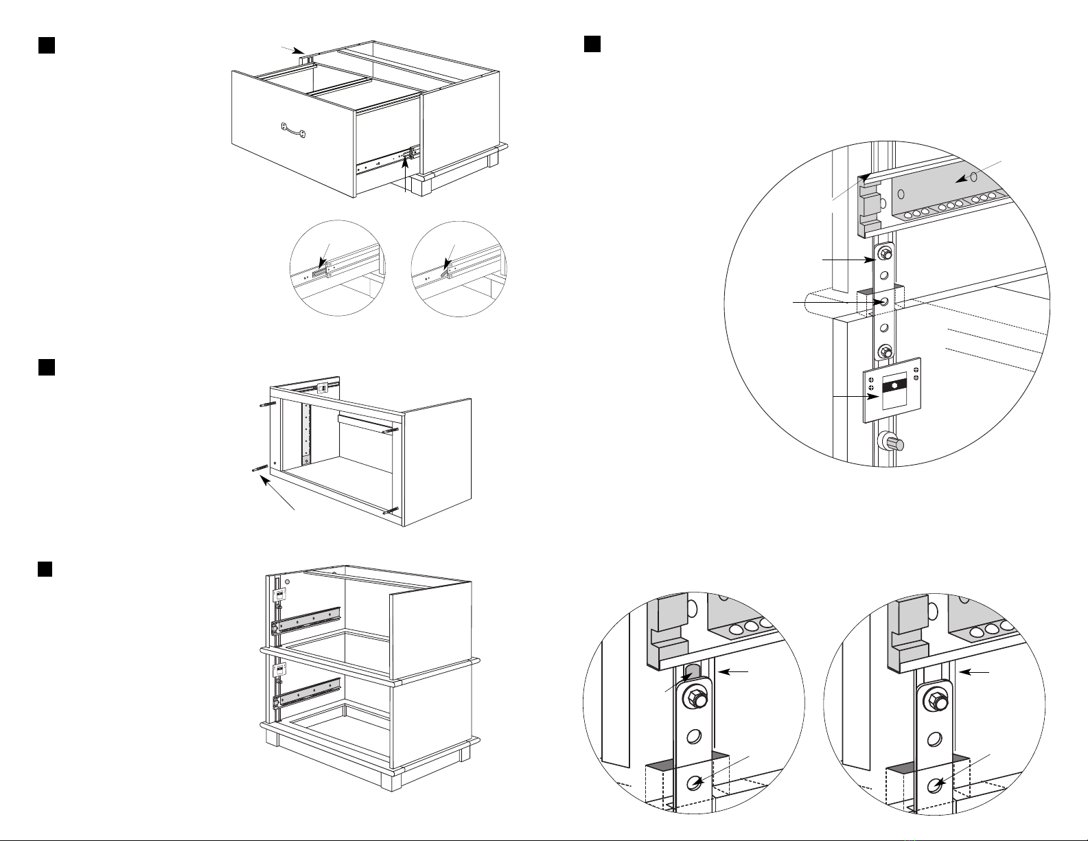
Attaching the splicers
Find the lock bars located on the left interior of each unit. Put all the lock bars
into the middle position by moving them up and down.
Locate and examine the splicer. The splicer allows only one drawer to be opened at
a time. On the back of each splicer bolt are two small wings. (See illustration
below.) Loosen the nuts until they are
halfway undone. Align the splicers
with the lock bars, and be sure
the wings start out in a
vertical position. Align the
splicer and its wings with
the slot of the lock bar.
Slide it down so the
center hole in between
the drawers cannot be
seen. Hold the splicer
in place.
Tighten both the upper
and lower nuts with a
1⁄4" socket wrench or
pliers until both wings
disappear. The wings will
disappear within the lock bar
when they are fully tightened. (The
diagrams below show the two positions;
left shows the upper clip in the unlocked position; right shows the locked position.)
Make sure it is snug and does not slip. Test by moving the lock bar up and down. If
the splicer wings do not disappear, loosen the nuts more and try again. Do not be
discouraged if it takes you a few trials to lock the splicer in place.
7
splicer
center
hole
black bar
glide
anti-tip
interlock
lock bar
lock bar
unlocked position
center
hole
splicer
wing
locked position
center
hole
lock bar
Attaching the units
Locate the four holes on the top of
Unit 1. Pick up Unit 2 and set it on
top of Unit 1 with the mini-lock
screws extending into the holes of
Unit 1. Insert a mini-lock nut into
each of the four holes on the inside
of Unit 1. Make sure the arrow on
each mini-lock nut faces out and
lines up with its mini-lock screw.
When fully inserted, use the
screwdriver and turn each mini-lock nut
clockwise approximately 1⁄2turn, locking it
into position.
Unit 1
Unit 2
mini-lock screws
Unit 2
Prepping Unit 2
The upper section of your file
will be referred to as Unit 2. Lay
Unit 2 on the floor on its base
and remove the drawer as you
did for Unit 1. Lay the unit’s
frame on its back and insert a
mini-lock screw into each of the
four holes on the bottom.
5
6
Removing the drawer
Lay Unit 1 on the floor on its
base. Pull the drawer straight
out until it will go no farther.
(If the drawer is locked into
position and will not open,
push in on the lock bar located
inside the unit to the left.) Locate
the plastic tab on each side of the
drawer glides. You will use these tabs to
release the drawer. If your cabinet has
tabs, push in on the tabs on both sides to
release the drawer. If your cabinet has
levers, push the lever on the left side up
and the lever on the right side down.
Hold as you pull the drawer completely
out of the frame. There will be some
resistance, but it should ride smoothly.
4
tab lever
lock bar
tab


